
Patent CN105599508B
Updated November 6, 2026Automatic Feed Pencil Sharpener with Visual Indicator
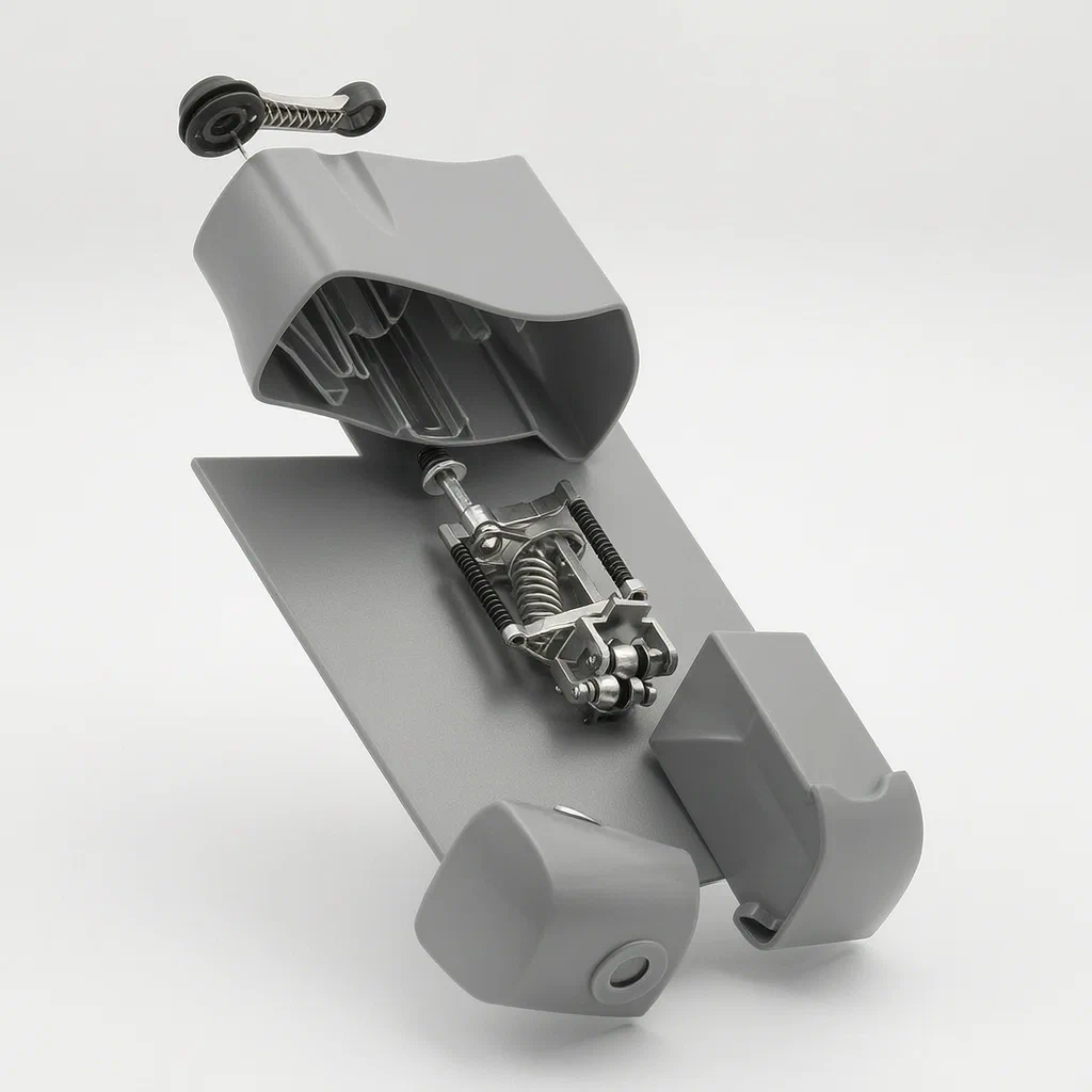
Standard sharpeners require constant pressure from the user to keep the pencil against the blades, leading to uneven wear and hand fatigue. This design automates the feeding process. A spring-loaded holder pushes the cutter into the pencil as it rotates. Once the tip is formed, the holder retracts. A visible marker on the outside of the body tracks this movement, letting users know exactly when the sharpening cycle is complete without opening the unit.
- China invention patent - active
- No filings outside China
- Stationery & School Supplies
- Plastic body, metal gears, spring-loaded mechanism
Splat! What let you down?
🔄
Auto-return mechanism
Springs push the cutter holder back to the start position after each use.
👁️
Visual status indicator
A moving point on the exterior shows when the blade has fully engaged.
✏️
Flexible clamping
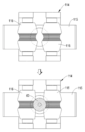
Design supports either elastic rollers or lockable jaws for holding pencils.
⚙️
Gear-driven cutting
A drive mechanism connects the motor or handle to the rotating cutter module.
Bring this product to market
- ✓ Patent review Patent family and legal status reviewed in the relevant jurisdictions.
- 2 Product brief · now How it works, uses and options written up
- 3 Prototype First samples for buyers to review
- 4 Pilot run Small first batch for launch customers
- 5 Volume production Repeat orders at scale
Buyer interest
– of 100 buyers needed to start prototyping
One click, no sign-up. Each vote is one real visitor, and products with the most interest go to prototyping first.
Build team: no members yet. Need a partner, co-funding or skills to build this? Join and we introduce the team once it forms.
Patent Rights & Team Participation
Before joining a development team, participants should ensure they have the necessary rights or authorization to participate in the project.
Participation is generally appropriate where:
- You own the relevant patent rights or have obtained permission or a license from the rights holder.
- The relevant patent rights have expired or have been legally invalidated in the jurisdictions where the planned activities will take place.
- The planned development, manufacturing, and commercialization activities have been independently assessed and do not infringe applicable patent rights in the relevant jurisdictions.
Important: Being located outside a country where a patent is protected does not automatically exempt you from patent infringement risks. Patent rights may apply based on where development, manufacturing, use, sale, or import activities take place.
IP2M does not grant any patent license or authorization through team participation. Joining a project does not provide permission to use, manufacture, or commercialize patented technology.
The problem
Manual pencil sharpening requires the user to apply steady inward pressure while turning the crank or holding the pencil in an electric unit. If the pressure varies, the pencil tip breaks or becomes dull. Electric sharpeners often lack feedback on when the pencil is fully sharpened, causing users to over-sharpen and waste lead. Traditional designs also struggle to hold different pencil diameters securely without complex adjustments.
The solution
- Movable Cutter Holder: The blade assembly is mounted on a holder that slides linearly within the body’s internal space, guided by specific grooves.
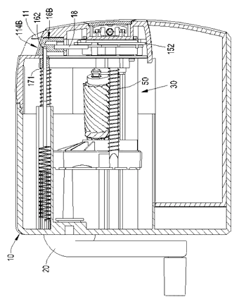
- Spring Return System: Elastic elements (springs) connect the holder to the body, constantly pushing the holder away from the pencil entry hole unless acted upon by external force or mechanism logic.
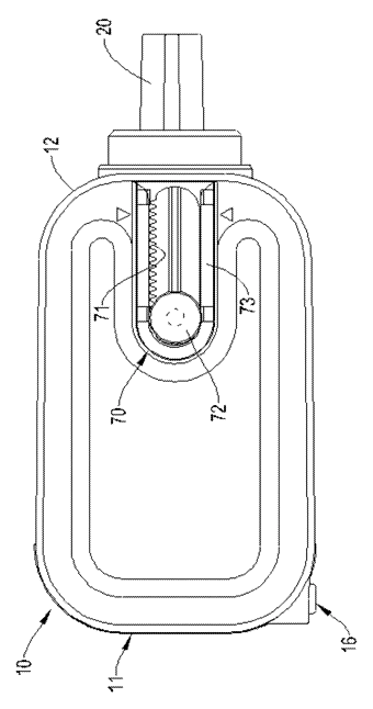
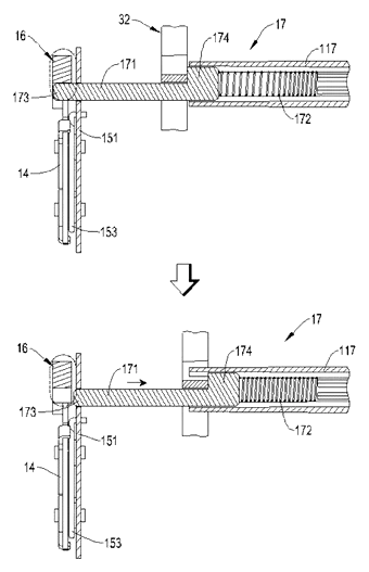
- Visual Feedback: A track on the body’s surface holds a moving point connected to the cutter holder. As the holder advances to cut, the point moves along the track, indicating progress.
- Clamping Options: The entry area features either elastic rollers that grip the pencil naturally or a button-operated jaw system that locks the pencil in place during operation.
Who it is for
- School Supply Brands: Looking for durable, easy-to-use sharpeners for classrooms where students may not apply consistent pressure.
- Office Equipment Manufacturers: Producing desktop accessories that need clear operational feedback to prevent over-sharpening and waste.
- Art Supply Companies: Creating tools for sketching pencils that require precise tip formation without breaking fragile leads.
- Toy & Novelty Makers: Developing safe, interactive stationery items with visible mechanical actions that appeal to younger users.
How it works
The main parts
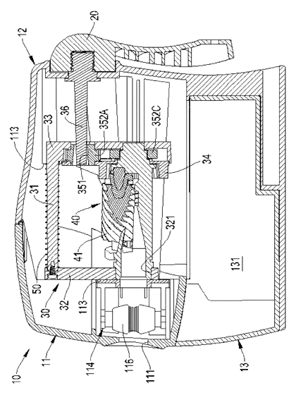
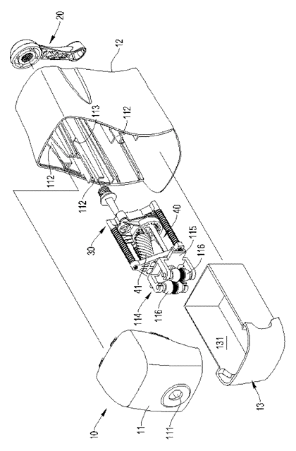
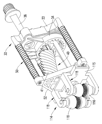
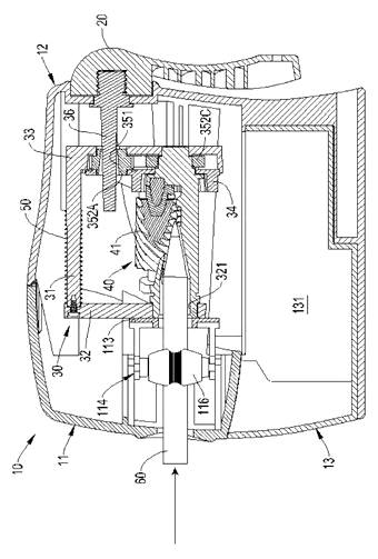
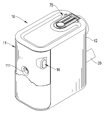
| No. | Part | What it does |
|---|---|---|
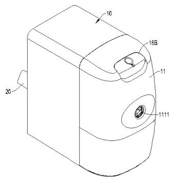
| 10 | Body | Main housing with front/back walls and internal guide grooves. |
| 111 | Entry Hole | Opening in the first wall where the pencil is inserted. |
| 30 | Cutter Holder | Slides linearly; carries the blade module. |
| 40 | Cutter Module | Rotating blades that shave the wood and lead. |
| 50 | Elastic Element | Springs that return the holder to the resting position. |
| 112 | Guide Grooves | Channels that constrain the holder’s movement. |
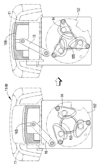
| 114 | Pencil Holding Mechanism | Rollers or jaws that secure the pencil during sharpening. |
| 17 | Visual Device | Track and moving point indicating holder position. |
Operating Steps
- Insertion: The user inserts a pencil into the entry hole. The holding mechanism (rollers or jaws) grips the shaft.
- Activation: The drive device (motor or manual crank) engages. The cutter holder moves forward against the spring tension, bringing the blades into contact with the pencil.
- Sharpening: The cutter module rotates relative to the holder, shaving the pencil. The holder continues to advance until the desired tip geometry is achieved or resistance changes.
- Retraction: When the cycle ends or the user releases the trigger/button, the springs push the cutter holder back to its original position.
- Indication: Throughout the process, the visual point moves along the external track, showing the user the current state of the cutter’s engagement.
Applications
Classroom Stations
Students can insert a pencil and let the machine do the work. The visual indicator helps them understand when the sharpening is complete, reducing broken tips common with inexperienced users.
Artist Studios
Artists using soft charcoal or colored pencils benefit from the controlled feed rate. The auto-return feature prevents the blade from digging too deep into delicate cores, preserving expensive art materials.
Office Desks
In busy office environments, the self-returning mechanism ensures the sharpener is always ready for the next user. The compact design fits easily on desks without requiring manual resetting.
Children’s Toys
The moving external pointer acts as a simple mechanical display, engaging children with the visible action of the internal parts. It teaches basic cause-and-effect relationships through everyday objects.
Where it is less suitable
- Heavy Industrial Use: Plastic bodies and small springs may not withstand continuous high-volume commercial usage compared to metal industrial models.
- Very Large Diameter Pencils: The fixed entry hole and clamp spacing limit compatibility to standard-sized writing instruments.
- Silent Environments: The spring return and gear meshing may produce noise unsuitable for libraries or quiet offices if not dampened.
Patent & Production
At a glance
| Patent number | CN105599508B (application CN201610034221) |
| Type | China invention patent (发明专利) - protects product shape, structure, and method |
| Original title | A type of automatic pencil sharpener (一种自动进笔之削笔机) |
| Patent owner | Shunde Stationery (Jiangsu) Co., Ltd. |
| Inventors | Du Bingfeng |
| Filing date | 2016-01-19 |
| Grant date | 2018-04-17 |
| Status (China) | In force - valid until at most 2036-01-19, provided annual fees are paid |
| Patent family | Public record shows Chinese filings only - no US, European, Japanese, PCT or other filings listed |
| Cited by | 0 later documents |
| Source | Google Patents (search for CN105599508B) |
What the claims cover, in plain language
Claim 1 defines an automatic pencil sharpener comprising a body with two opposing walls and an entry hole. A cutter holder is positioned between these walls and can move linearly towards or away from the entry hole. A cutter module is attached to this holder and rotates via a driving device. An elastic element (spring) pushes the holder back to its starting position. Crucially, a visual device is included: a moving point on the body’s exterior tracks the holder’s position, driven by an actuator on the holder itself.
Claims 2-7 specify the mechanics: multiple guide grooves inside the body constrain the holder’s path. Support rods on the holder slide in these grooves. Springs are wound around these rods, anchored between the body and the holder to provide the return force. The holder includes front and rear support frames forming a rigid structure.
Claims 8-9 describe the drive mechanism, which uses gears and connecting rods to transfer power from the driving device (motor or manual crank) to the rotating cutter module.
Claims 10-16 detail the pencil holding mechanism. One embodiment uses elastic rollers fixed near the entry hole to grip the pencil. Another uses clamping jaws operated by a button and lock. Pressing the button extends the jaws to grip; locking the button keeps them extended. Releasing the lock allows the jaws to retract automatically.
Claim 17 elaborates on the visual device, specifying a track on the outer surface and a dynamic point moved by the holder’s rear frame.
This is a simplified reading for orientation only. The legal scope is defined by the exact claim wording in the official Chinese document.
What this means for US production
This patent was filed in China and is currently in force. Making or selling this specific configuration in China requires the owner’s permission. However, the public record shows no US counterpart. Therefore, producing and selling this design in the United States is not restricted by this specific patent document.
Two points to settle early:
- Other patents may exist. Automatic pencil sharpeners are a competitive field with many existing patents covering various feed mechanisms, blade assemblies, and safety interlocks. A freedom-to-operate (FTO) review is recommended to ensure no other US patents cover the specific spring-return and visual-indicator combination.
- Component Sourcing. The design relies on specific molded plastic guide slots and custom-length springs. Ensuring consistency in spring tension and plastic molding tolerances is critical for the auto-return function to work reliably across units.
Customization and manufacturing
What can be customized
| Area | Options |
|---|---|
| Drive Type | Manual crank (external handle) or Electric motor (internal battery/AC adapter) |
| Holding Mechanism | Simple elastic rollers or complex button-lock jaws |
| Visual Indicator | Color-coded track segments, transparent window vs. solid slider |
| Material | ABS or PP for body; stainless steel or carbon steel for blades |
| Color & Finish | Matte, glossy, or textured plastics; custom printing on the body |
| Capacity | Size of the shavings collection box |
Things to plan for (US market)
- ASTM F963 - Consumer Product Safety Standard for toys; applies if marketed to children under 12. Requires testing for small parts, sharp edges, and pinch points.
- CPSC Regulations - General safety requirements for household goods, particularly regarding electrical components if an electric version is made (UL certification may be required depending on power source).
- California Prop 65 - Screening for heavy metals in paints, platings, and plastics.
- Battery Compliance - If electric, UN 38.3 transport standards for lithium batteries and FCC Part 15 for electromagnetic interference.
How a project runs
- Inquiry - Define drive type (manual/electric), target age group, and quantity.
- Design - Finalize mold layouts for the body and holder, select spring rates, and determine visual indicator style.
- Prototype - Create 3D-printed samples to test the sliding mechanism and spring return. Assemble off-the-shelf springs for functional testing.
- Pilot Run - Produce limited quantities using tooling. Test cycle life, pencil grip strength, and visual indicator accuracy.
- Production - Injection molding of plastic parts, stamping of metal blades/gears, assembly of motors/springs, and packaging.
Quantities & timeline
Tooling for the complex internal guide slots and the multi-part holder will require precision molds. Spring selection and tuning are key cost drivers. Assembly steps involving the button-lock mechanism (if chosen) add labor time. Certification tests for ASTM F963 (if applicable) take several weeks. Send us your drive preference, material choices, estimated quantity and target price and we will reply with options.
Production notes
Tooling and process
Injection molding is likely the primary process for the body and cutter holder due to the intricate internal guide grooves. Metal stamping will be used for the blades and gear teeth. Motor assembly involves integrating the drive unit into the rear compartment.
Cost drivers
The number of molds is typically significant given the separate parts for the body, holder, and visual track. Spring quality and consistency are major cost factors, as weak or inconsistent springs will fail the auto-return function. Additional assembly steps for the button-lock mechanism increase labor costs.
Prototyping path
We would typically start with a 3D-printed sample to verify the fit of the holder in the guide grooves. Use off-the-shelf springs to test the return force. Conduct a function and cycle test to ensure the visual indicator moves smoothly without jamming. Print trials for graphics should follow structural validation.
What we would change before tooling
We would optimize the wall thickness of the guide slots to prevent cracking under repeated stress. We might simplify the spring anchoring points to reduce assembly time. Checking hinge boss and pivot wear areas in the CAD model is essential before finalizing the mold.
Common failure points
Clip spring loss is a risk if the anchoring tabs are too thin. Hinge fatigue may occur in the button-lock mechanism if the plastic is brittle. Shaft and bearing alignment issues could cause the cutter to wobble. Edge hardness must be sufficient to prevent rapid dulling of the blades.
Patent drawings
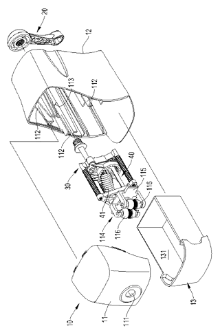
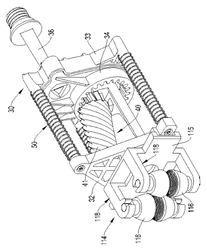
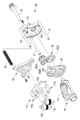
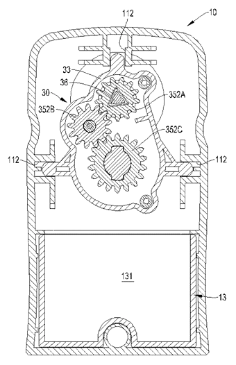
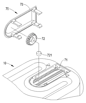
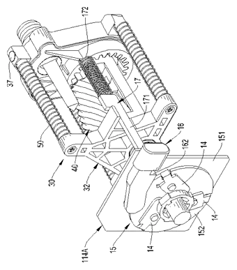
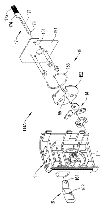
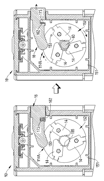
Drawings reproduced from the public patent document for reference.
Frequently asked questions
How does the auto-return work?
The cutter holder is pushed backward by springs located in the internal guide grooves. When you activate the sharpener, the mechanism overrides the spring force to move the blades forward. Once the cycle stops, the springs immediately pull the holder back to its resting position, clearing the way for the next pencil.
What is the visual indicator?
It is a mechanical display on the outside of the body. A small pointer moves along a track as the internal cutter holder advances. This lets you see how far the blades have engaged with the pencil without opening the unit.
Does it hold the pencil automatically?
Yes. The design includes a pencil holding mechanism. In one version, elastic rollers grip the pencil shaft firmly. In another, a button-operated jaw system locks the pencil in place to prevent slipping during sharpening.
Can it sharpen large diameter pencils?
The entry hole size is fixed by the mold. While it accommodates standard school and office pencils, very thick art pencils or markers may not fit. Custom entry hole sizes can be requested during the design phase.
Is it electric or manual?
The patent describes both possibilities. A manual version uses a crank handle connected to the gears. An electric version uses a motor housed within the body. The core auto-feed and visual indicator mechanism remains the same in both configurations.
Why use a spring instead of a motor for return?
Springs are simpler, cheaper, and more reliable than adding a second motor for retraction. They provide immediate reset action without needing electronic controls or sensors.
Can this design be made and sold in the US?
The patent is in force in China, but the public record shows no US counterpart. Therefore, making and selling this specific design in the United States is not restricted by this patent. However, other US patents may cover similar automatic feed technologies, so a freedom-to-operate check is recommended.
Are you affiliated with the patent owner?
No. IP2M is an independent design and manufacturing service working from the public patent document.
Request a quote
Click Request a Quote below to see our email address - copy it, or open your email app with a ready-made message. Please mention patent CN105599508B in the subject.
Helpful details to include:
- Your company and channel (school supply brand, office equipment maker, toy manufacturer)
- Drive type preference (manual crank or electric motor)
- Holding mechanism choice (rollers or button-lock jaws)
- Material and color specifications
- Estimated quantity and target price
- Timeline - when you would like samples and the first shipment
You can also reach us at (332) 203-9997.
Page editor: Daniel Chen, Product Research Editor · IP2M
Last updated November 6, 2026. If something on this page looks wrong, email [email protected] and we will check it against the patent.
Interested in building this?
Tell us your target market, quantity and timeline. We reply with options for prototyping, small-batch runs or volume production.
Send your inquiry to
Please put CN105599508B in the subject line and tell us your company, country, estimated quantity and timeline.
Prefer to talk? Call (332) 203-9997.
More product-ready patents
All School, Office & Art patents →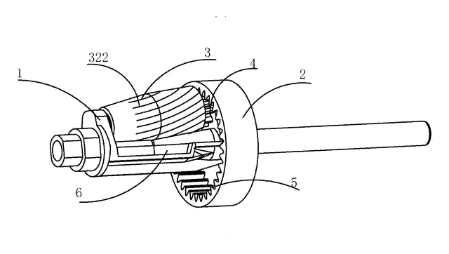
School, Office & Art
Long-Point Sketch Pencil Sharpener
Crank sharpener that cuts only the wood of sketch pencils, leaving a long, round lead about 30 mm long.
Patent CN207241257U
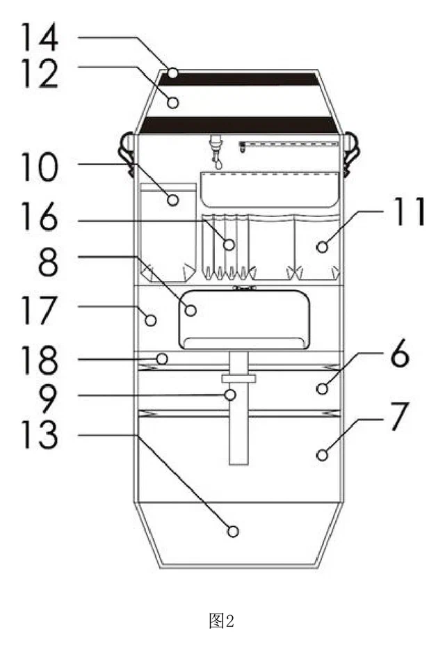
School, Office & Art
Fold-Out Desk Organizer Insert for School Backpacks
Backpack insert that unfolds into a hanging desk organizer for workbooks, stationery and a water bottle.
Patent CN209436546U
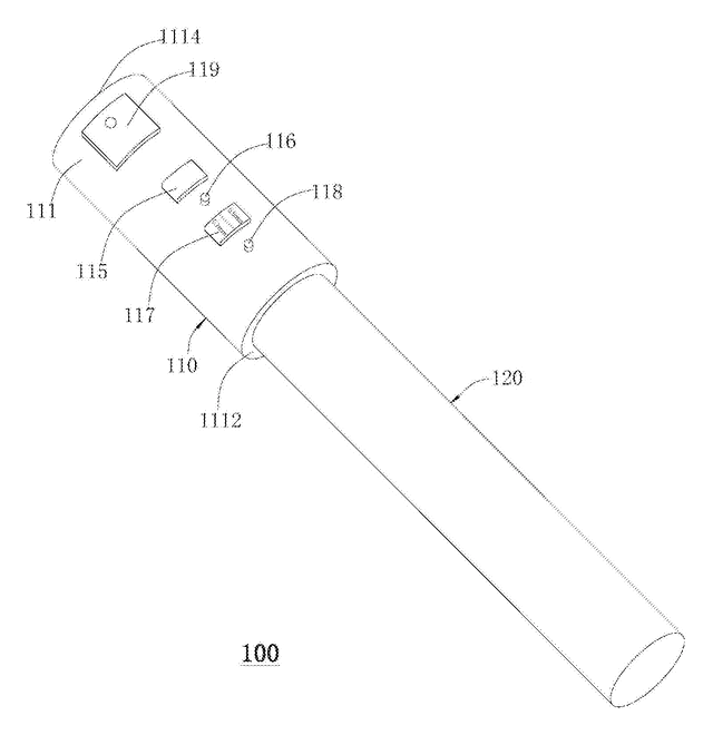
School, Office & Art
Smart Pencil Cap That Checks the Point with a Camera
Electronic pencil cap that photographs the point, measures it and reminds you to sharpen.
Patent CN106427302B
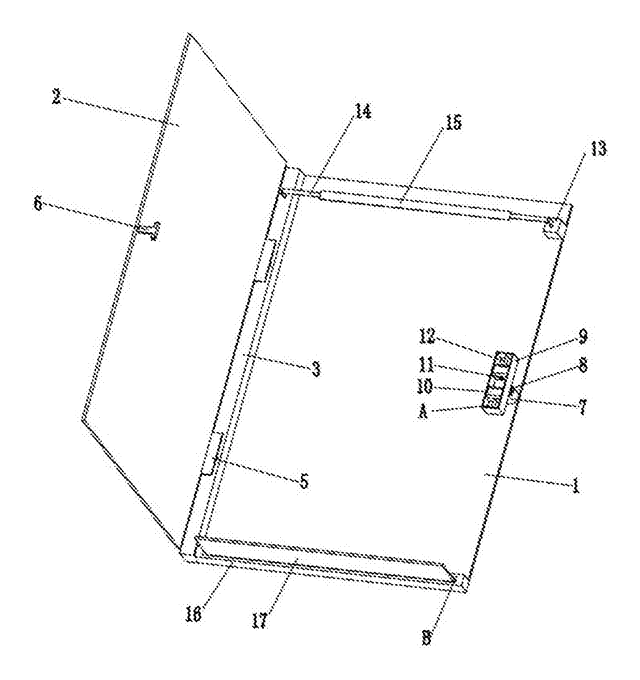
School, Office & Art
Expanding Clipboard Folder with Spring-Mounted Hinge and Catch
Hard folder whose spring-mounted hinge and catch let the cover clamp any thickness of paper.
Patent CN105667120B
School, Office & Art
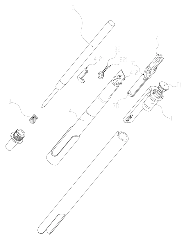
Slide-Action Retractable Pen with a Friction-Loaded Cam That Ignores Gravity
Slide-action retractable pen whose spring-pressed cam latch stays put whichever way the pen is held.
Patent CN217671900U
School, Office & Art
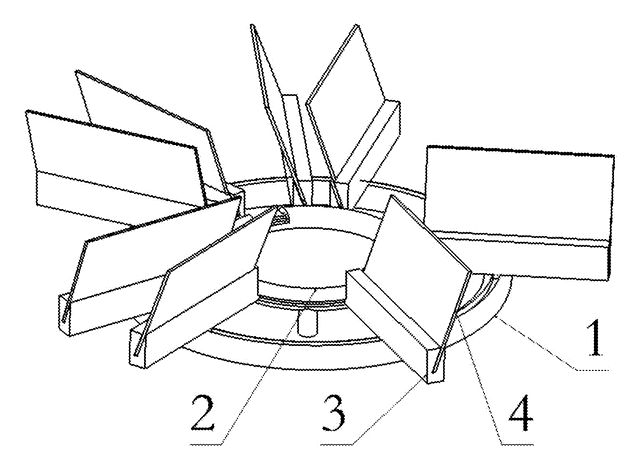
Carousel Business Card Holder with Rolling Card Trays on Twin Ring Tracks
Desk card holder: angled card trays roll on wheels around two concentric ring tracks and lift out.
Patent CN105774300B
Browse by category
- Apparel & Accessories (45)
- Baby & Kids (28)
- Bags & Luggage (16)
- Bath & Personal Care (30)
- Car Accessories (24)
- Furniture, Bedding & Storage (23)
- Garden & Outdoor (31)
- Health & Wellness (13)
- Home, Kitchen & Cleaning (48)
- Lighting (22)
- Packaging & Containers (12)
- Pet Products (11)
- Phone & Camera Accessories (9)
- Retail Display (24)
- School, Office & Art (34)
- Sports & Recreation (44)
- Tools & Workshop (53)
- Toys & Games (22)
This page is based on the public patent document CN105599508B, assigned to Shunde Stationery (Jiangsu) Co., Ltd.. IP2M is an independent manufacturing service and is not affiliated with, endorsed by or licensed by the patent owner. Images marked as concept renderings are illustrations, not photos of an existing product. Patent status information is provided for reference only and is not legal advice; confirm freedom to operate for your market before production. Full disclaimer.