At a glance
| Patent number | CN105710904B (application CN201610171338) |
| Type | China invention patent (发明专利) - protects product shape, structure and method |
| Original title | A convenient driving round cutter of one kind cutting (一种切割方便的推动式圆形切刀) |
| Patent owner | Individual |
| Inventors | Zhang Zujie |
| Filing date | 2016-03-24 |
| Grant date | 2017-09-12 |
| Status (China) | Lapsed - terminated for non-payment of annual fees (recorded 2023-03-10) |
| Patent family | Chinese filings only - no US, European, Japanese, PCT or other filings listed |
| Cited by | 1 later document |
| Source | Google Patents (search for CN105710904B) |
What the claims cover, in plain language
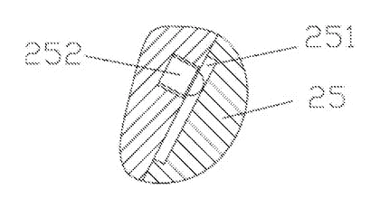
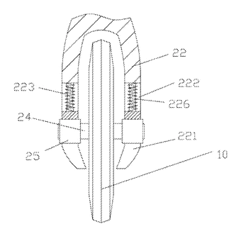
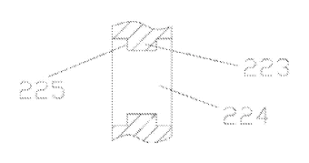
Claim 1 describes a push-style round cutter comprising a round cutter and a toolframe. The toolframe has a handle portion with two side support arms at its front bottom surface. The round cutter is fixed on a central rotating shaft, whose ends hinge into bearing connecting blocks positioned between the side support arms. An extension groove extends upward from the bottom of each side support arm, communicating at its top with a long through groove in the middle of the arm. Raised items line the two sides of the long through groove. A movable block sleeves inside the long through groove, guided by vertical grooves on its sides fitting over the raised items. A buffer spring sits in the long through groove, pressing between its top surface and the movable block. The movable block is a permanent magnetic iron block with an arc groove on its bottom surface, into which the bearing connecting block sleeves and is magnetically adsorbed.
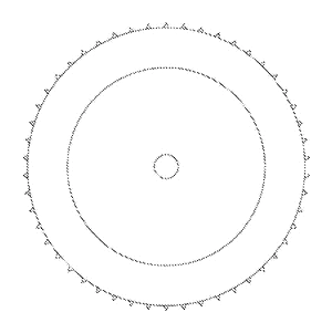
Claim 2 adds that the movable block has an upper projection and the long through groove has a lower convexity, with the buffer spring sleeved between them. Claim 3 specifies an overcoat fixed to both outer walls of the handle portion. Claim 4 states the lateral wall of the round cutter is zigzag. Claim 5 notes the round cutter forms a circular shear blade at the two ends of the central rotating shaft. Claim 6 details a spacing bulb plunger bolted to the side wall of the extension groove, with its steel ball nesting into a spacing elongated slot on the bearing connecting block.
This is a simplified reading for orientation only. The legal scope is defined by the exact claim wording in the official Chinese document.
What this means for US production
This patent was filed only in China and is lapsed, having been terminated for non-payment of annual fees in 2023. It therefore no longer restricts anyone in China, and it has no US or other foreign counterpart.
Two points to settle early:
- Other patents may exist. Hand-held rolling cutters and pizza wheels are a mature category with many active US and international patents covering blade guards, ergonomic handles, and quick-release axles. One later publication (WO2023249337A1) cites this Chinese patent, assigned to 김정표 (Kim Jeong-pyo), indicating ongoing patent activity in this field. A freedom-to-operate (FTO) review of the magnetic mount and spring buffer mechanism is recommended before launching production.
- Magnet safety and food contact. The permanent magnetic iron block sits near the cutting area. Material selection must ensure the magnet is fully encapsulated or made of food-safe, corrosion-resistant material so it cannot contaminate food or degrade during washing.
Customization and manufacturing
What can be customized
| Area | Options |
|---|---|
| Wheel profile | Zigzag lateral wall, circular shear blade, or straight edge |
| Wheel diameter | To be confirmed in design based on target food thickness |
| Handle overcoat | Material, texture, and color of the grip sleeves |
| Frame material | Plastic injection molding or die-cast metal for the toolframe |
| Spring rate | Buffer spring stiffness adjusted for heavy or light doughs |
| Magnet strength | Sized to hold the bearing block securely but allow manual pull-release |
Things to plan for (US market)
- FDA 21 CFR - materials contacting food (the wheel, the frame around it, and any encapsulation over the magnet) must comply with FDA food-contact regulations.
- California Proposition 65 - the handle overcoat, plated shaft and frame plastic need a check for listed chemicals such as lead and BPA before the product ships to California.
How a project runs
- Inquiry - wheel size, material preferences, target use case, and estimated volume.
- Design - CAD modeling of the toolframe, sizing the buffer spring, selecting the magnet grade, and designing the spacing bulb plunger.
- Prototype - 3D printed or CNC machined samples to test the magnetic release force, spring compression, and rolling action.
- Pilot run - injection molds or die-cast dies are opened; initial units undergo food-safety material testing and cycle tests on the magnetic mount.
- Production - mass molding, magnet insertion, spring assembly, wheel stamping or molding, and final packaging.
Quantities & timeline
The toolframe requires injection molds or die-casting dies depending on the chosen material, while the round cutters need stamping dies or separate molds for the zigzag or shear profiles. The buffer springs and spacing bulb plungers are standard hardware components sourced to specification. Food-contact certification tests add time before the first shipment. Send us your wheel size, material preferences, handle color, quantity and target price and we will reply with options.
Patent drawings
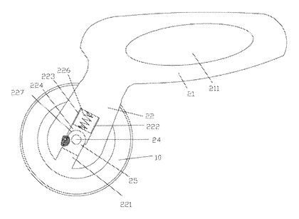
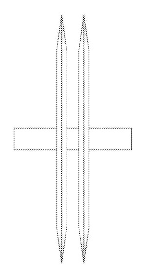
Drawings reproduced from the public patent document for reference.