
Patent CN105805510B
Updated October 25, 2026Surveying Tripod with Bevel-Gear Micro-Leveling and Circular Bubble Scale
Leveling a standard surveying tripod means wrestling with telescopic leg clamps while watching a tiny vial bubble drift past the mark. This design adds a geared micro-adjustment on every leg while retaining telescopic leg sections. A side-mounted handle turns a bevel-gear pair that drives a threaded screw vertically through thrust bearings, moving the leg tip by small, controlled increments. Above the legs, a circular glass level shows three principal lines radiating from the center—each aligned with one leg—plus concentric secondary rings, so the operator immediately knows which leg to turn and how far. A central adjusting rod sets the overall height, and a bottom hook takes a plummet or ballast disk to hold the setup steady in wind.
- China invention patent - lapsed
- No filings outside China
- Surveying and measurement equipment
- Bevel-gear micro-adjustment
Splat! What let you down?
⚙️
Bevel-gear micro-adjustment
Each leg has a side handle that turns a bevel-gear pair, driving a screw vertically for fine height control.
🎯
Radial bubble scale
Three principal lines on the glass level point toward each leg, showing exactly which one to adjust.
📏
Coaxial height rod
An adjusting rod slides inside the central seat to set the working height before locking.
⚓
Plummet or ballast hook
A hook under the adjustment seat holds a plummet for centering or a weight disk for wind stability.
Bring this product to market
- ✓ Patent vetted China-only family and legal status checked
- 2 Product brief · now How it works, uses and options written up
- 3 Prototype First samples for buyers to review
- 4 Pilot run Small first batch for launch customers
- 5 Volume production Repeat orders at scale
Buyer interest
– of 100 buyers needed to start prototyping
One click, no sign-up. Each vote is one real visitor, and products with the most interest go to prototyping first.
Build team: no members yet. Need a partner, co-funding or skills to build this? Join and we introduce the team once it forms.
The problem
Setting up a conventional surveying tripod over a ground mark involves loosening leg clamps, sliding sections by hand, retightening, checking the bubble, and repeating until the instrument is roughly level. On uneven terrain this cycle takes time, and coarse sliding makes it easy to overshoot the mark. Standard tubular bubble levels also give limited directional feedback, forcing the operator to guess which leg to move. According to the patent, the goal is a tripod that is quick to operate, easy to adjust, and efficient for measurement work.
The solution
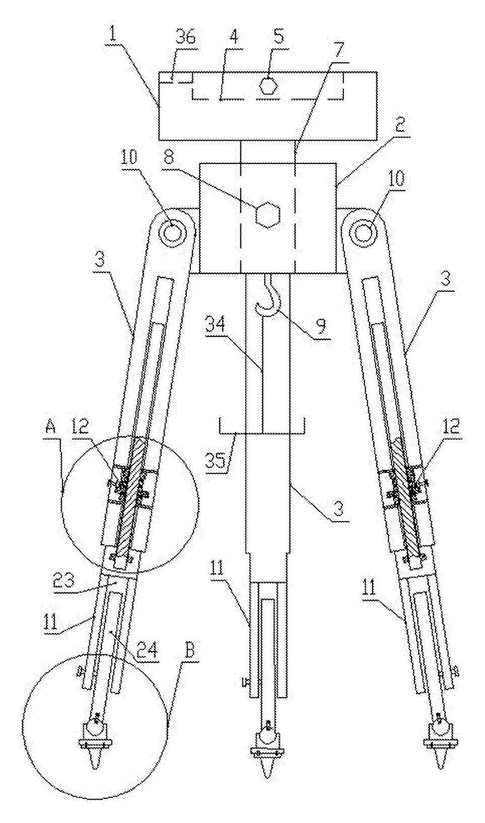
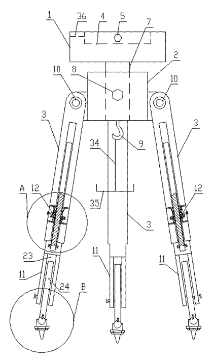
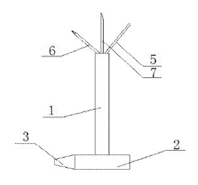
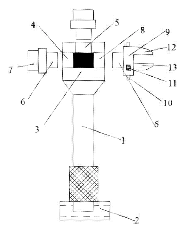
- The instrument fixed seat (1) has a circular fixing groove (4) at its center. Three lock-screws (5) thread in from the sides, each ending in an arc spacer (6) that presses against the instrument base.
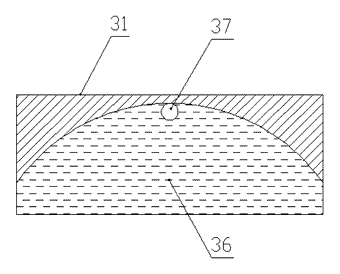
- A bubble and scale assembly (36) is embedded beside the groove. It uses a round glass panel (31) printed with three principal mark lines (32) radiating from the center—each corresponding to one leg—and several concentric secondary graticules (33).
- An adjusting rod (7) hangs vertically from the seat’s underside and slides coaxially into the adjustment seat (2). A fastening bolt (8) locks it at the desired height.
- A hook (9) at the bottom of the adjustment seat suspends a plummet or a load-carrying disk (35) via a bracing wire (34).
- Three supporting legs (3) hinge to the adjustment seat through hinges (10). Each leg ends in a retractive leg section (11) containing a telescopic cavity (23) with an expansion link (24) secured by a clamping screw (25).
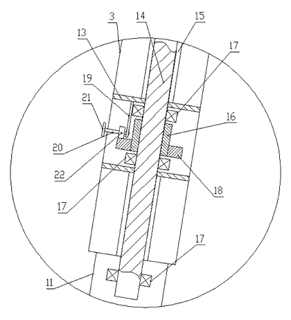
- A micro-adjusting mechanism (12) sits near the bottom of each supporting leg. It houses a transmission case (13) containing an adjusting screw rod (14) that rides in a guide groove (15). A bushing (16) threaded onto the rod is supported by two thrust bearings (17) and carries a first bevel gear (18) keyed to it. A horizontal rotating shaft (20) on a mounting seat (19) holds a second bevel gear (22) meshing with the first, and ends in a regulation handle (21) outside the leg.
- The expansion link terminates in a support foot: a bulb (29) fixed to the expansion link by studs (28) and hinged on a support base (26), with a replaceable fixed pin (27)—either a cone nail for soft ground or a rubber cushion block for hard surfaces—attached by a mounting screw (30).
Who it is for
- Surveying instrument brands looking for a tripod to bundle with total stations and optical levels, where fast setup reduces crew downtime.
- Construction layout contractors who set up and break down tripods dozens of times per day on job sites and need repeatable leveling without fighting leg clamps.
- Photogrammetry and laser-scanning service providers whose accuracy depends on a level base and who benefit from fine-threaded adjustment rather than manual sliding.
- Equipment rental companies supplying tripods to field crews; the geared mechanism reduces wear from operators overtightening friction clamps.
How it works
The main parts
| No. | Part | What it does |
|---|---|---|
| 1 | Instrument fixed seat | Holds the surveying instrument in the fixing groove (4). |
| 4 | Fixing groove | Circular recess centered on the seat. |
| 5, 6 | Lock-screw and arc spacer | Clamp the instrument base from three sides. |
| 36, 31 | Bubble and scale / glass panel | Shows level status with radial and concentric marks. |
| 32, 33 | Principal mark lines / secondary graticules | Indicate which leg to adjust and how far off level it is. |
| 7 | Adjusting rod | Slides inside the adjustment seat to set height. |
| 2 | Adjustment seat | Central hub connecting the rod and the three legs. |
| 8 | Fastening bolt | Locks the adjusting rod at the chosen height. |
| 9, 34, 35 | Hook, bracing wire, load-carrying disk | Suspends a plummet or ballast weight. |
| 3, 10 | Supporting leg / hinge | Three legs pivoting from the adjustment seat. |
| 11, 23, 24, 25 | Retractive leg, cavity, expansion link, clamping screw | Telescopic coarse extension locked by a screw. |
| 12 | Micro-adjusting mechanism | Fine height adjustment assembly on each leg. |
| 13 | Transmission case | Houses the gears and screw. |
| 14, 15 | Adjusting screw rod / guide groove | Moves vertically when the bushing turns. |
| 16, 17 | Bushing / thrust bearings | Threaded sleeve supported axially by bearings. |
| 18, 22 | First and second bevel gears | Transfer rotation from the horizontal shaft to the vertical bushing. |
| 20, 19, 21 | Rotating shaft, mounting seat, regulation handle | Operator turns the handle outside the leg. |
| 26, 29, 27, 30 | Support base, bulb, fixed pin, mounting screw | Hinged foot accepting a spike or rubber pad. |
Setup and leveling steps
- Spread the legs and place the tripod over the ground mark. Hang the plummet from the hook (9) so it aligns with the crosshair on the ground.
- Select the foot pin: attach the cone nail for soft soil or the rubber cushion block for pavement using the mounting screw (30). For extra stability, hang the load-carrying disk (35) and add stones or weights.
- Coarse level: loosen the clamping screws (25) on the retractive legs (11), slide the expansion links (24) until the bubble (37) falls within the smallest secondary graticule (33), then retighten.
- Set height: loosen the fastening bolt (8), slide the adjusting rod (7) to raise or lower the instrument seat (1), and retighten.
- Mount the instrument: place it in the fixing groove (4) and turn the three lock-screws (5) so the arc spacers (6) grip the base.
- Fine level: read the bubble position relative to the three principal mark lines (32). Turn the regulation handle (21) on the corresponding leg. The handle spins the rotating shaft (20) and second bevel gear (22), which meshes with the first bevel gear (18) on the bushing (16). Because the bushing is threaded onto the adjusting screw rod (14) and held by thrust bearings (17), its rotation drives the rod up or down along the guide groove (15), changing that leg’s effective length by small increments until the bubble centers.
Applications
Topographic land surveying
Crews working across hillsides and ditches constantly change tripod positions. The geared micro-adjustment lets them dial in a level base without repeatedly loosening friction clamps, saving time at every station.
Construction site layout
Staking out foundations requires frequent setups on compacted dirt or concrete slabs. Swapping between cone nails and rubber pads keeps the feet secure, while the plummet hook ensures the instrument stays centered over the stake.
Monitoring and deformation measurement
Long-term monitoring prisms demand repeatability. Fine-threaded screw adjustments provide more controlled movements than sliding tubes, helping technicians return the bubble to the exact same center position during repeated visits.
Photogrammetry and drone base-station setup
Ground control points for aerial mapping often sit in open fields exposed to wind. Hanging a weight disk from the bottom hook lowers the center of gravity, reducing vibration transmitted to the GPS receiver mounted above.
Where it is less suitable
- Lightweight hiking or backpacking surveys - the transmission cases, gears and thrust bearings add mass compared to simple clamp tripods.
- High-vibration environments such as pile driving - continuous heavy shock loads could accelerate wear on the bevel gears and bushings.
- Budget consumer-grade instruments - the added machining and assembly cost exceeds what entry-level rotary lasers or basic levels require.
Frequently asked questions
How does the micro-adjustment actually move the leg?
Turning the side handle rotates a horizontal shaft carrying a bevel gear. That gear meshes with a bevel gear keyed to a threaded bushing inside the transmission case. The bushing is held axially by two thrust bearings but free to spin. As it turns, it drives the adjusting screw rod up or down along its guide groove, extending or retracting the leg tip by small increments.
Why are there three lines on the bubble level?
The three principal mark lines radiate from the center of the glass panel, each aligned with one of the tripod legs. When the bubble sits off-center, the operator sees immediately which line—and therefore which leg—needs adjustment, eliminating the trial-and-error guessing common with plain circular vials.
Can the legs be made from wood instead of metal?
Yes. The patent describes the mechanical joints and gear assemblies independently of the leg body material. Wooden legs would require metal ferrules or inserts where the hinges and transmission cases attach, but the core leveling mechanism remains the same.
What is the maximum instrument weight it supports?
The patent does not specify a load rating. Maximum capacity is determined during engineering by selecting the leg tube diameter, wall thickness, gear module, screw diameter and hinge pin size, then verified by static and dynamic load tests.
How do the interchangeable foot pins work?
The support base at the bottom of each expansion link has a mounting screw hole. A cone nail is attached for soft soil penetration, or a rubber cushion block attaches for hard surfaces like concrete. The user swaps them manually before setup.
Does the central adjusting rod rotate when changing height?
The adjusting rod slides coaxially inside the adjustment seat. Once the desired height is reached, a fastening bolt threads through the side of the adjustment seat to press against the rod, locking it in place.
Can this design be made and sold in the US?
The patent was filed only in China and has lapsed due to non-payment of annual fees, so it does not restrict the design in the US or in China. Surveying tripod mechanisms may be covered by other US patents - see Patent & Production - so we recommend a freedom-to-operate check before volume production.
Are you affiliated with the patent owner?
No. IP2M is an independent design and manufacturing service working from the public patent document.
Request a quote
Click Request a Quote below to see our email address - copy it, or open your email app with a ready-made message. Please mention patent CN105805510B in the subject.
Helpful details to include:
- Your company and channel (surveying brand, construction equipment distributor, rental fleet operator)
- Target instrument weight and type (optical level, total station, GNSS receiver)
- Preferred leg material (aluminum, fiberglass, wood)
- Required extended and collapsed lengths
- Estimated quantity and target price
- Timeline - when you would like samples and the first shipment
You can also reach us at (332) 203-9997.
Explore this product
Interested in building this?
Tell us your target market, quantity and timeline. We reply with options for prototyping, small-batch runs or volume production.
Send your inquiry to
Please put CN105805510B in the subject line and tell us your company, country, estimated quantity and timeline.
Prefer to talk? Call (332) 203-9997.
More product-ready patents
All Tools & Workshop patents →
Tools & Workshop
Rolling Tool Box with Telescoping Step Ladder
Telescoping A-frame ladder with an attached rolling tool box that slides to your working height.
Patent CN206290197U
Tools & Workshop
Folding 3-Handle Wrench Multi-Tool
Folding three-handle wrench multi-tool with magnetic screwdriver bits, saw, file and bottle opener.
Patent CN205290875U
Tools & Workshop
Rolling Auto-Repair Tool Cabinet with Built-In Lights
Lockable rolling tool cabinet for car repair with interior lights, a lubricant tray, parts drawers and a tool bay.
Patent CN205989314U
Tools & Workshop
Wide-Opening Folding Bolt Cutter
Bolt cutter with linked, gear-meshing handles that open up to 190° and fold in half for storage.
Patent CN207206226U
Tools & Workshop
Nail-Holding Hammer with Fold-Out Drivers
Hammer with a nail-holding T-slot in the head and fold-out drivers stored in the handle.
Patent CN205254927U
Tools & Workshop
Modular Wrench with Screw-On Heads
Wrench handle with a three-way threaded hub for screw-on adjustable and hex heads, plus a pipe sleeve.
Patent CN206216564U
Browse by category
- Apparel & Accessories (22)
- Baby & Kids (16)
- Bags & Luggage (9)
- Bath & Personal Care (16)
- Car Accessories (10)
- Furniture, Bedding & Storage (12)
- Garden & Outdoor (18)
- Health & Wellness (8)
- Home, Kitchen & Cleaning (24)
- Lighting (12)
- Packaging & Containers (6)
- Pet Products (6)
- Phone & Camera Accessories (4)
- Retail Display (13)
- School, Office & Art (19)
- Sports & Recreation (25)
- Tools & Workshop (27)
- Toys & Games (12)
This page is based on the public patent document CN105805510B, assigned to Individual (Wang Yuzhen). IP2M is an independent manufacturing service and is not affiliated with, endorsed by or licensed by the patent owner. Images marked as concept renderings are illustrations, not photos of an existing product. Patent status information is provided for reference only and is not legal advice; confirm freedom to operate for your market before production. Full disclaimer.