
Patent CN105818115B
Updated November 6, 2026Safety Hammer with Reinforced Head Attachment and Anti-Slip Grip
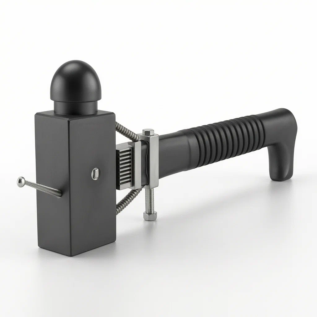
Standard hammers rely on friction or simple wedges to hold the head, which can loosen over time or fail under heavy impact, causing dangerous detachment. This design introduces a multi-stage locking mechanism. The hammerhead connects to the handle stem via a rectangular inserted link and screw reinforcement. Steel bars welded to the head connect to a collar, which is clamped onto the handle stem using two nuts. Additionally, the handle includes a textured grip and a safety rope to prevent the tool from slipping out of the user's hand during swinging motions.
- China invention patent - lapsed
- No filings outside China
- Hand tools & workshop equipment
- Steel components, threaded fasteners, rope grip
Splat! What let you down?
🔨
Mechanical Head Lock
Head attaches via rectangular link, screws, and a collar clamped by nuts.
🛡️
Dual Reinforcement
Steel bars welded to the head connect to the collar, securing it even if screws loosen.
✋
Anti-Slip Grip
Concave handle with textured veins and end-mounted ropes to prevent hand slippage.
🔩
Adjustable Assembly
Collar slides on chutes and locks with first and second clamp nuts for firm fixation.
Bring this product to market
- ✓ Patent review Patent family and legal status reviewed in the relevant jurisdictions.
- 2 Product brief · now How it works, uses and options written up
- 3 Prototype First samples for buyers to review
- 4 Pilot run Small first batch for launch customers
- 5 Volume production Repeat orders at scale
Buyer interest
– of 100 buyers needed to start prototyping
One click, no sign-up. Each vote is one real visitor, and products with the most interest go to prototyping first.
Build team: no members yet. Need a partner, co-funding or skills to build this? Join and we introduce the team once it forms.
Patent Rights & Team Participation
Before joining a development team, participants should ensure they have the necessary rights or authorization to participate in the project.
Participation is generally appropriate where:
- You own the relevant patent rights or have obtained permission or a license from the rights holder.
- The relevant patent rights have expired or have been legally invalidated in the jurisdictions where the planned activities will take place.
- The planned development, manufacturing, and commercialization activities have been independently assessed and do not infringe applicable patent rights in the relevant jurisdictions.
Important: Being located outside a country where a patent is protected does not automatically exempt you from patent infringement risks. Patent rights may apply based on where development, manufacturing, use, sale, or import activities take place.
IP2M does not grant any patent license or authorization through team participation. Joining a project does not provide permission to use, manufacture, or commercialize patented technology.
The problem
In conventional hardware hammers, the head is typically attached to the handle using a wedge or friction fit within an eye hole. Over repeated impacts, this connection can loosen, leading to head wobble or, in severe cases, complete detachment during use. A detached head poses a significant safety hazard to the operator and bystanders. Furthermore, standard smooth handles can slip from the user’s grip when hands are sweaty or gloved, reducing control and increasing the risk of injury. There is a need for a hammer that ensures the head remains securely fixed regardless of vibration and provides a reliable grip interface.
The solution
The patent proposes a hammer structure where the connection between the head and handle is mechanically locked rather than relying solely on friction.
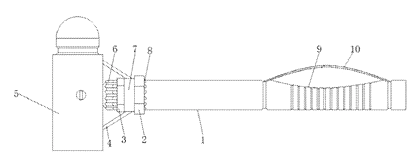
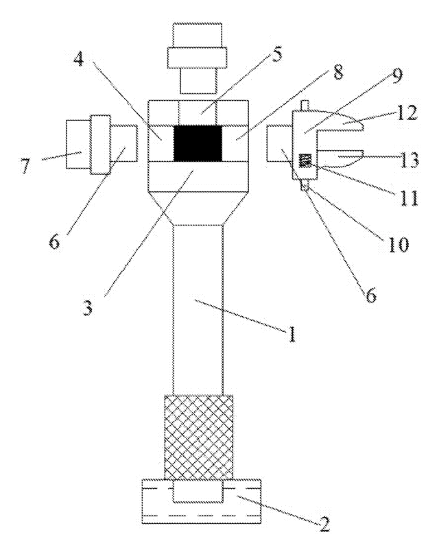
- The hammer stem (1) has a right-hand end formed as a grip section (9) with a concave top surface and anti-slip veins.
- A gear rope (10) is attached to the sides of the grip section to block hand slippage.
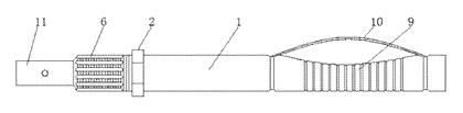
- The left end of the stem features alternating external threads and chutes (6).
- An inserted link (11) with a rectangular cross-section is integrally formed at the stem’s left end.
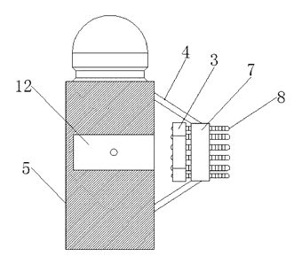
- The hammerhead (tup) (5) has a slot (12) on its right flank that receives the inserted link (11).
- A screw secures the head to the link through the slot.
- Two steel bars (4) are welded to the head’s left flank, positioned on either side of the slot.
- These steel bars connect to the lateral surface of a collar (7).
- The collar contains internal draw runners (8) that slide into the chutes (6) on the stem.
- The draw runners have external threads engaged by a first clamp nut (2) and a second clamp nut (3), locking the collar—and thus the head—to the stem.
Who it is for
- Industrial Tool Manufacturers: Companies looking to differentiate their product line with enhanced safety features for construction and maintenance crews.
- Professional Contractors: Users who require tools that minimize downtime due to broken heads and offer secure handling in slippery conditions.
- Workshop Equipment Suppliers: Distributors serving automotive, metalworking, and general repair sectors where tool reliability is critical.
- Safety-Focused Brands: Brands aiming to market products specifically for high-risk environments where tool failure could cause injury.
How it works
The main parts
| No. | Part | What it does |
|---|---|---|
| 1 | Hammer Stem | Main body; includes grip, threads, chutes, and inserted link. |
| 5 | Tup (Head) | Impact face; contains slot for link insertion. |
| 11 | Inserted Link | Rectangular extension from stem; fits into head slot. |
| 12 | Slot | Opening in head receiving the link; allows screw passage. |
| 4 | Steel Bars | Welded to head; connect head to collar for secondary lock. |
| 7 | Collar | Ring surrounding stem; connects to steel bars and draw runners. |
| 8 | Draw Runners | Internal tabs on collar; slide into stem chutes; have threads. |
| 2, 3 | Clamp Nuts | First and second nuts; tighten against draw runners to lock collar. |
| 6 | Chutes | Grooves on stem allowing draw runner movement. |
| 9 | Grip Section | Concave handle area with anti-slip veins. |
| 10 | Gear Rope | Ropes at grip ends to prevent hand sliding off. |
Operating Steps
- Insertion: The rectangular inserted link (11) on the stem is pushed into the slot (12) of the hammerhead (5).
- Primary Fixation: A screw is driven through the head into the link, creating a rigid connection between head and stem.
- Collar Alignment: The collar (7) is positioned around the stem. Its internal draw runners (8) align with the chutes (6) on the stem.
- Secondary Locking: The steel bars (4) welded to the head are connected to the collar’s exterior.
- Clamping: The first clamp nut (2) and second clamp nut (3) are tightened onto the threaded draw runners (8). This pulls the collar firmly against the stem structure.
- Result: Even if the primary screw loosens or breaks, the collar-nut system maintains the head’s position relative to the stem via the steel bars.
Applications
Construction Sites
Workers use this hammer for framing and demolition tasks where high impact forces are common. The dual-locking mechanism prevents head detachment, reducing workplace hazards.
Automotive Repair
Mechanics strike stubborn bolts and components. The anti-slip grip and rope ensure control when hands are oily or wearing gloves, preventing accidental slips that could damage vehicle parts or injure the user.
Metal Fabrication Shops
Fabricators perform repetitive striking operations. The robust collar assembly absorbs vibration better than traditional wedges, maintaining tight tolerances in the tool itself over long shifts.
General Maintenance
Facility managers equip staff with durable tools. The design simplifies potential repairs since the head attachment is bolted and clamped rather than wedged, allowing for easier inspection of wear points.
Where it is less suitable
- Light-Duty Household Use: The complex mechanical assembly adds weight and cost compared to basic claw hammers needed for hanging pictures.
- Precision Woodworking: Carpenters requiring fine control often prefer lighter, traditional wooden-handle hammers without metal collars interfering with swing dynamics.
- Extreme Cold Environments: While not explicitly excluded, metal-on-metal threading mechanisms may seize if ice forms in the chutes, unlike simpler solid-head designs.
Patent & Production
At a glance
| Patent number | CN105818115B (application CN201610384483) |
| Type | China invention patent (发明专利) - protects product structure and method |
| Original title | A high-security-performance hardware hammer (一种安全性能高的五金锤) |
| Patent owner | CHANGZHOU JINHAILONG MACHINE MANUFACTURING Co Ltd |
| Inventors | Shi Xueqin |
| Filing date | 2016-06-02 |
| Grant date | 2018-04-10 |
| Status (China) | Lapsed - terminated for non-payment of annual fees (recorded 2019-05-21) |
| Patent family | Public record shows Chinese filings only - no US, European, Japanese, PCT or other filings listed |
| Cited by | 0 later documents |
| Source | Google Patents (search for CN105818115B) |
What the claims cover, in plain language
Claim 1 defines a hammer comprising a stem (1) and a tup/head (5). Key features include:
- A grip section (9) at the right end of the stem with a concave top and anti-slip veins.
- A gear rope (10) attached to the sides of the grip section.
- Alternating external threads and chutes (6) on the left end of the stem.
- A first clamp nut (2), a collar (7), and a second clamp nut (3) arranged on the stem’s left side.
- An inserted link (11) integrally formed at the stem’s left end with a rectangular vertical cross-section.
- The tup (5) has a slot (12) on its right flank that receives the inserted link (11).
- A screw connects the tup and inserted link through the slot.
- Two steel bars (4) are welded to the tup’s left flank, positioned on both sides of the slot, and connect to the lateral surface of the collar (7).
- The collar (7) has internal draw runners (8) equidistantly positioned and slidably connected to the chutes (6).
- Each draw runner (8) has external threads.
- The left-side draw runners connect to the stem via the second clamp nut (3).
- The right-side draw runners connect to the stem via the first clamp nut (2).
Claim 2 specifies that the gear rope (10) has both ends located at the respective both sides of the grip section (9).
This is a simplified reading for orientation only. The legal scope is defined by the exact claim wording in the official Chinese document.
What this means for US production
This patent was filed in China and has lapsed, so it no longer restricts anyone in China. The public record shows no US or other foreign counterpart.
Two points to settle early:
- Other patents may exist. Hand tools are a mature field with extensive existing prior art. While this specific collar-and-link mechanism appears unique in the public record, similar safety features (such as captive head designs or alternative locking wedges) may be covered by active US patents held by major tool manufacturers. A freedom-to-operate (FTO) review is recommended before mass production.
- Material Specifications. The patent mentions steel bars and threads but does not specify grades. Manufacturing must define material standards (e.g., heat-treated steel for the head, corrosion-resistant coatings) to meet durability expectations in the US market.
Customization and manufacturing
What can be customized
| Area | Options |
|---|---|
| Head Weight | Standard variations (e.g., 16oz, 20oz, 24oz) based on casting/forging size |
| Handle Material | Steel stem as described; potentially composite wraps or different grip textures |
| Fasteners | Thread pitch and nut sizes can be adjusted for assembly speed vs. holding power |
| Finish | Zinc plating, powder coating, or black oxide for rust resistance |
| Rope Type | Braided nylon, Kevlar, or rubberized cord for the gear rope feature |
| Welding Process | MIG or TIG welding for the steel bar attachments to the head |
Things to plan for (US market)
- ANSI B107.1 - Hand tools standard covering physical properties and performance requirements for hammers.
- OSHA Guidelines - General duty clause requires tools to be maintained in safe working condition; documentation of stress testing helps compliance.
- California Prop 65 - If using certain coatings or materials, warnings may be required regarding chemicals known to cause cancer or reproductive harm.
How a project runs
- Design Validation - Confirm dimensions of the rectangular link and slot tolerance.
- Prototyping - Create functional samples using machined stems and cast heads.
- Testing - Conduct impact tests to verify the collar does not loosen under repeated strikes.
- Tooling Preparation - Prepare molds for head casting and fixtures for welding/collaring.
- Production Ramp-up - Begin small batch production with quality checks on thread engagement.
Quantities & timeline
Molds for the hammerhead and machining fixtures for the stem are required. Injection molding is not applicable unless plastic components are added (not in original patent). Welding stations for attaching steel bars to the head need precise jigs. Assembly involves manual or automated tightening of clamp nuts. Send us your target volume, finish preferences, and weight specifications and we will reply with options.
Production notes
Tooling and process
The hammerhead likely requires die-cast aluminum or forged steel depending on desired weight and strength. The stem involves machining to create the rectangular link and threaded sections. Stamping dies may be used for the collar if stamped steel is chosen, though casting is likely more typical for this geometry. Heat treatment is essential for the head’s hardness.
Cost drivers
Material costs for steel and aluminum typically dominate. Machining time for the precise rectangular link and chutes adds expense. The number of stamping dies or casting molds directly impacts upfront tooling costs. Surface finish requirements also influence processing steps.
Prototyping path
We would typically start with a 3D-printed handle mockup to test grip ergonomics. Use a machined or off-the-shelf blade/blank for the head initially. Create heat-treatment trial coupons to validate hardness specs. Assemble a functional sample to test the collar lock mechanism before committing to full tooling.
What we would change before tooling
We would likely add a polymer insert to the grip for comfort, though this deviates from the pure metal design. Verify that the rectangular link shape is optimal for torsional resistance versus a circular pin with flats. Ensure the weld joints between steel bars and head are accessible for automated welding robots.
Common failure points
Edge hardness below spec leads to mushrooming of the head. Pivot pin wear is not applicable here, but thread engagement issues can cause the collar to loosen. Handle creep under load might occur if the stem material is too soft. Coating wear on the chutes could impede draw runner movement. Shaft alignment errors during machining affect the fit of the inserted link.
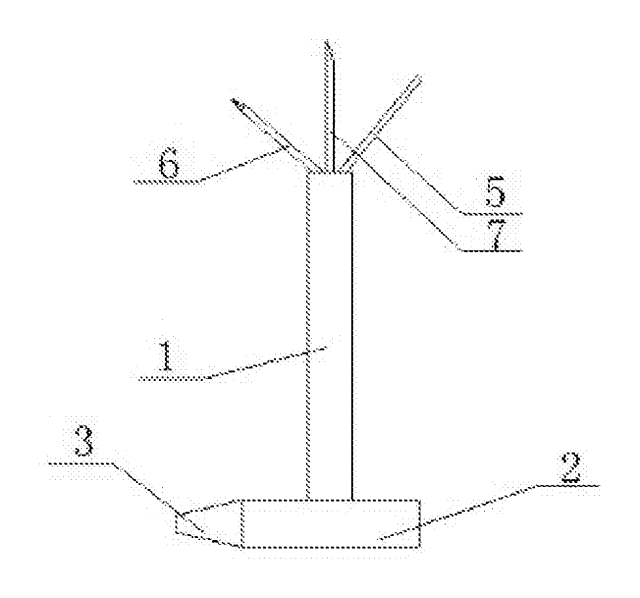
Patent drawings
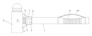
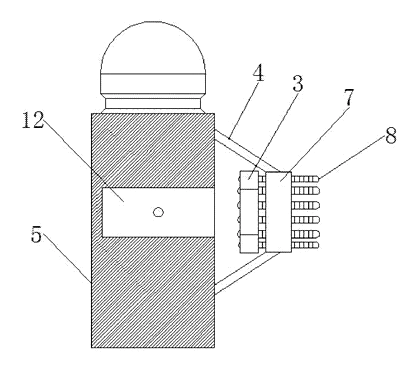
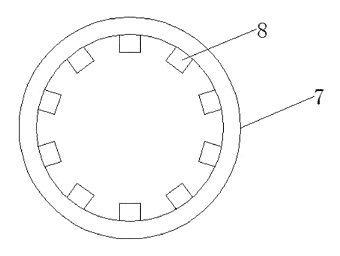
Drawings reproduced from the public patent document for reference.
Frequently asked questions
How does the head stay attached?
The head connects to the handle via a rectangular inserted link screwed into place. Additionally, a collar surrounds the handle, connected to the head by welded steel bars. This collar is clamped tight using two nuts, providing a secondary lock that holds the head even if the primary screw fails.
Why is there a rope on the handle?
The gear rope sits at the ends of the grip section. It acts as a physical barrier to stop your hand from sliding off the end of the handle during powerful swings, especially if your hands are wet or gloved.
Is the handle made of wood?
No. The patent describes a metal hammer stem with integrated threads and grooves. The grip section is part of this metal stem, featuring concave curves and textured veins for better hand contact.
Can I customize the head weight?
Yes. While the patent doesn’t specify weights, standard manufacturing practices allow for different head masses (e.g., 16oz to 24oz) by adjusting the casting or forging mold size.
Does the collar loosen over time?
The design uses clamp nuts to secure the collar. Proper torque during assembly is critical. Regular inspection of the nuts is recommended to ensure they remain tight after heavy use.
Are spare parts available?
Since the collar and nuts are threaded components, standard replacement hardware can be sourced if lost. However, the custom-shaped inserted link and welded steel bars make the head-stem assembly difficult to repair piece-by-piece; usually, the whole unit is replaced.
Can this design be made and sold in the US?
The patent was filed in China and has lapsed, and the public record shows no US counterpart, so it does not restrict the design in the US. However, always check for other active patents in the hand-tool sector before launching.
Are you affiliated with the patent owner?
No. IP2M is an independent design and manufacturing service working from the public patent document.
Request a quote
Click Request a Quote below to see our email address - copy it, or open your email app with a ready-made message. Please mention patent CN105818115B in the subject.
Helpful details to include:
- Your company and channel (tool distributor, industrial supplier, brand owner)
- Target head weight and handle length
- Material preference (forged steel, cast iron, etc.)
- Finish (plated, painted, raw)
- Estimated quantity and target price
- Timeline - when you would like samples and the first shipment
You can also reach us at (332) 203-9997.
Page editor: Emily Zhang, Product Editor · IP2M
Last updated November 6, 2026. If something on this page looks wrong, email [email protected] and we will check it against the patent.
Interested in building this?
Tell us your target market, quantity and timeline. We reply with options for prototyping, small-batch runs or volume production.
Send your inquiry to
Please put CN105818115B in the subject line and tell us your company, country, estimated quantity and timeline.
Prefer to talk? Call (332) 203-9997.
More product-ready patents
All Tools & Workshop patents →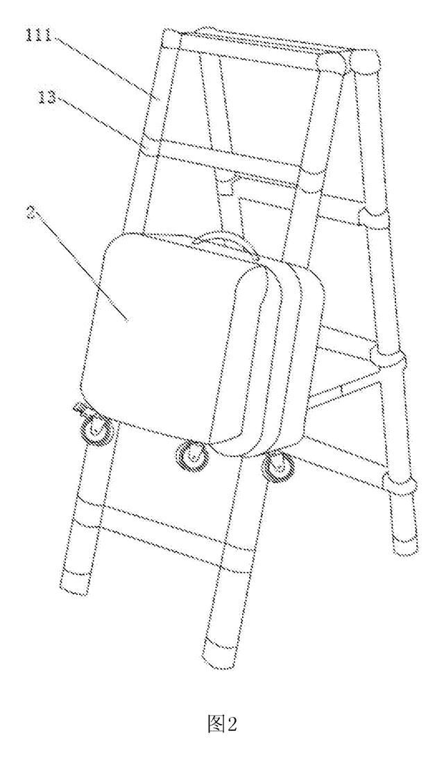
Tools & Workshop
Rolling Tool Box with Telescoping Step Ladder
Telescoping A-frame ladder with an attached rolling tool box that slides to your working height.
Patent CN206290197U
Tools & Workshop
Folding 3-Handle Wrench Multi-Tool
Folding three-handle wrench multi-tool with magnetic screwdriver bits, saw, file and bottle opener.
Patent CN205290875U
Tools & Workshop
Rolling Auto-Repair Tool Cabinet with Built-In Lights
Lockable rolling tool cabinet for car repair with interior lights, a lubricant tray, parts drawers and a tool bay.
Patent CN205989314U
Tools & Workshop
Wide-Opening Folding Bolt Cutter
Bolt cutter with linked, gear-meshing handles that open up to 190° and fold in half for storage.
Patent CN207206226U
Tools & Workshop
Nail-Holding Hammer with Fold-Out Drivers
Hammer with a nail-holding T-slot in the head and fold-out drivers stored in the handle.
Patent CN205254927U
Tools & Workshop
Modular Wrench with Screw-On Heads
Wrench handle with a three-way threaded hub for screw-on adjustable and hex heads, plus a pipe sleeve.
Patent CN206216564U
Browse by category
- Apparel & Accessories (45)
- Baby & Kids (28)
- Bags & Luggage (16)
- Bath & Personal Care (30)
- Car Accessories (24)
- Furniture, Bedding & Storage (23)
- Garden & Outdoor (31)
- Health & Wellness (13)
- Home, Kitchen & Cleaning (48)
- Lighting (22)
- Packaging & Containers (12)
- Pet Products (11)
- Phone & Camera Accessories (9)
- Retail Display (24)
- School, Office & Art (34)
- Sports & Recreation (44)
- Tools & Workshop (53)
- Toys & Games (22)
This page is based on the public patent document CN105818115B, assigned to CHANGZHOU JINHAILONG MACHINE MANUFACTURING Co Ltd. IP2M is an independent manufacturing service and is not affiliated with, endorsed by or licensed by the patent owner. Images marked as concept renderings are illustrations, not photos of an existing product. Patent status information is provided for reference only and is not legal advice; confirm freedom to operate for your market before production. Full disclaimer.