At a glance
| Patent number | CN105965549B (application CN201610517332) |
| Type | China invention patent (发明专利) - protects product structure and method |
| Original title | Folding knife with convenient belt clip dismounting (一种便于拆装皮带夹的折刀) |
| Patent owner | GUANGDONG TUOBITUO TECHNOLOGY Co.,Ltd. |
| Inventors | Zhou Hongfeng |
| Filing date | 2016-07-01 |
| Grant date | 2018-02-06 |
| Status (China) | In force - valid until at most 2036-07-01, provided annual fees are paid |
| Patent family | Chinese filings only - no US, European, Japanese, PCT or other filings listed |
| Cited by | 0 later documents |
| Source | Google Patents (search for CN105965549B) |
What the claims cover, in plain language
Claim 1 defines a folding knife with a handle containing a cavity, a blade with an installation portion and cutting edge, and a belt clip. The key structural elements are:
- Handle Construction: Composed of a first side plate and a second side plate, connected by a “sacrum” part with a threaded sleeve. Screws pass through the plates to join them.
- Blade Pivot: The blade rotates on a main shaft made of a female screw and a male screw, passing through holes in the side plates and blade. This allows the blade to be detached by unscrewing.
- Clip Mechanism: The first side plate has an inner plate and an outer plate. An elastic bar is attached to the inner plate. A baffle is on the outer plate facing the elastic bar, creating a gap. The outer plate has an inlet/outlet opening.
- Attachment Action: The belt clip has an L-shaped bending end. This end is pushed through the opening into the gap between the baffle and elastic bar. The elastic bar flexes to allow entry and then clamps the clip in place. Removal is done by pulling the clip out against the elastic force.
This is a simplified reading for orientation only. The legal scope is defined by the exact claim wording in the official Chinese document.
What this means for US production
This patent was filed only in China and is currently in force. Making or selling products that fall within the scope of these claims in China requires permission from the patent owner. For US production, there is no direct restriction from this specific Chinese patent, but local laws apply.
Two points to settle early:
- Other patents may exist. The folding knife market is highly competitive with numerous existing patents regarding pivot mechanisms, locking systems, and clip attachments. A freedom-to-operate (FTO) review is recommended to ensure no US patents cover similar tool-less clip mechanisms or screw-pivot designs.
- Material Specifications. The patent describes structural relationships but does not specify steel grades. Selecting appropriate materials for the elastic bar and blade is critical for performance and safety standards.
Customization and manufacturing
What can be customized
| Area | Options |
|---|---|
| Blade Steel | Common stainless steels (e.g., 8Cr13MoV, D2, S30V) depending on target price and hardness requirements. |
| Handle Material | Stamped steel, aluminum alloys, or textured plastics. Surface finishes include bead blasting, anodizing, or powder coating. |
| Clip Design | Different shapes or colors for the belt clip, provided they retain the L-shaped bending end compatible with the spring gap. |
| Pivot System | Adjustments to screw thread pitch or length to accommodate different handle thicknesses. |
| Locking Mechanism | The patent mentions a holding structure; variations in the elastic arm shape or stop bar material can be engineered. |
Things to plan for (US market)
- CPSC Regulations: General consumer product safety rules apply. Ensure sharp edges are properly packaged and warnings are included.
- State Laws: Knife ownership and carry laws vary significantly by state in the US. Marketing should respect regional restrictions (e.g., blade length limits).
- California Prop 65: If coatings contain lead or other listed chemicals, warning labels may be required.
- ANSI/BIFMA: Not directly applicable unless sold as office furniture, but general durability testing standards are good practice.
How a project runs
- Inquiry - Define target market, price point, and desired features (e.g., specific steel grade, handle texture).
- Design Review - Verify dimensions against the patent drawings. Check tolerance fits for the elastic bar and baffle gap.
- Prototyping - Create functional samples using machined parts or 3D printed handles to test the clip snap-action and pivot tightness.
- Testing - Perform cycle tests on the clip attachment/removal and blade deployment. Check for fatigue in the elastic bar.
- Production Setup - Prepare stamping dies for side plates, injection molds for plastic components (if any), and machining fixtures for blades.
Quantities & timeline
The complexity lies in the precision of the spring gap and the screw threads. Stamping dies for the multi-layer side plates will be needed. Injection molding for the elastic bar (if polymer-based) or machining it from steel strips affects cost. Assembly steps involve aligning the screws and testing the snap fit. Send us your target quantities, material preferences, and certification needs and we will reply with options.
Patent drawings
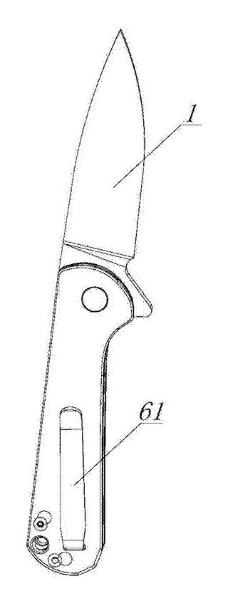
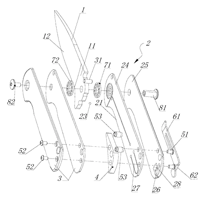
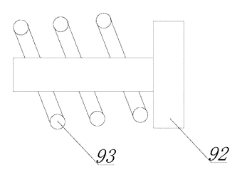
Drawings reproduced from the public patent document for reference.
Production notes
Tooling and process
Stamping dies are likely required for the first and second side plates to create the precise openings for the screws and the inlet/outlet for the clip. Machining is typically used for the blade and the threaded main shaft components. Heat treatment is essential for the blade edge hardness and potentially for the elastic bar to ensure proper spring-back characteristics.
Cost drivers
The number of stamping dies typically increases with the complexity of the side plate layers. Cutting edge machining costs depend on the steel grade selected. Surface finish requirements (e.g., polished vs. raw) also impact labor hours. Assembly steps involving the alignment of the screw pivot and the snap-test of the clip add to per-unit labor costs.
Prototyping path
Prototyping typically starts with a 3D-printed handle to verify the geometry of the clip gap and baffle interaction. Use off-the-shelf or machined blades for initial functional samples. Produce heat-treatment trial coupons to validate the elastic bar’s fatigue life before committing to full-scale tooling.
What we would change before tooling
We would likely adjust the tolerance fit between the L-shaped clip end and the elastic bar to balance retention strength against ease of removal. Testing different spring rates for the elastic bar would be prudent to prevent accidental release under vibration or intentional removal difficulty.
Common failure points
Edge hardness below spec could lead to rapid dulling. Pivot pin wear might occur if the screw threads loosen over time. Handle creep under load is a risk if the side plates deform. Spring fatigue is the primary concern for the clip mechanism, potentially leading to loss of retention force. Thread engagement issues could arise if screws are overtightened during assembly.