
Patent CN106347272B
Updated October 26, 2026Adjustable Vehicle Rear Bumper Guard with Telescopic Triangle Frame
Standard rigid rear bumpers on trucks and commercial vehicles often strike curbs, ramps, or uneven terrain because their height and angle are fixed. This design replaces the rigid mount with a mechanical linkage that adapts to the ground. A U-shaped pedestal bolts to the vehicle's stringer. Inside it, a sliding block moves along guide slots and guide rods. A first telescopic rod links the block to the rear bumper, allowing vertical lift. A second telescopic rod, fitted with a pre-tightened spring, acts as the diagonal brace of a right-angled triangle formed by the two rods and the slot. When the bumper hits an obstacle, the linkage compresses, the spring absorbs energy, and the bumper rides up or pushes back instead of hanging rigidly. Rollers mounted at the bottom of the bumper provide a rolling contact surface. Once the obstacle passes, the return springs and the main spring bring the assembly back to its resting position.
- China invention patent - in force
- No filings outside China
- Commercial vehicle & truck parts
- Steel rods, springs, rollers
Splat! What let you down?
📐
Adjustable triangle frame
Two telescopic rods and the pedestal slot form a right-angled triangle that changes shape to lift the bumper.
🔄
Rolling contact
Idler wheels extend below the bumper so the assembly rolls over obstacles instead of dragging.
🔩
Guided sliding block
The block slides inside a U-shaped pedestal on guide rods and T-shaped slots for stable movement.
🌀
Spring return
A pre-tightened spring on the diagonal rod and return springs on the guide rods reset the bumper after impact.
Bring this product to market
- ✓ Patent vetted China-only family and legal status checked
- 2 Product brief · now How it works, uses and options written up
- 3 Prototype First samples for buyers to review
- 4 Pilot run Small first batch for launch customers
- 5 Volume production Repeat orders at scale
Buyer interest
– of 100 buyers needed to start prototyping
One click, no sign-up. Each vote is one real visitor, and products with the most interest go to prototyping first.
Build team: no members yet. Need a partner, co-funding or skills to build this? Join and we introduce the team once it forms.
The problem
Commercial vehicles and trucks frequently encounter low departure angles when backing into loading docks, crossing speed bumps, or driving onto steep ramps. A conventional rigid rear bumper hangs at a fixed height below the chassis. When the vehicle reverses into an incline or an obstacle, the rigid bumper strikes it directly. This causes damage to the bumper, the chassis stringer, or the obstacle itself. Drivers must approach slowly or avoid certain routes entirely to prevent structural damage. The lack of vertical or horizontal compliance in standard rear guards limits the vehicle’s usable departure angle and reduces overall passability in tight or uneven environments.
The solution
This vehicle rear protecting device introduces a mechanical linkage that allows the bumper to move when it meets resistance.
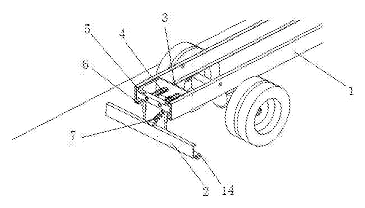
- A pedestal (3) with a U-shaped cross-section is fixed to the tail of the vehicle’s stringer (1). The pedestal includes side plates and a bottom plate.
- The inner lateral edges of the side plates feature sliding slots, which are bent inwards at the upper and lower ends to form a T-shaped structure.
- A sliding block (5) sits between the side plates, with both ends engaging the T-shaped slots. Guide rods (4) fixed to the bottom plate pass through via holes in the sliding block to keep its travel straight.
- A first telescopic rod (6) connects the bottom of the sliding block to the rear bumper (2), providing a vertical link.
- A second telescopic rod (7) connects the top of the rear bumper to the bottom plate diagonally. A spring (8) is pre-tightened on this second rod.
- Together, the first telescopic rod, the second telescopic rod, and the sliding slot surround an adjustable right-angled triangle, where the second telescopic rod acts as the bevel edge.
- Idler wheels (14) are mounted on roller fixing bases (15) at the back of the rear bumper, with their bottom acting surfaces extending downward past the bumper face.
Who it is for
- Commercial truck body builders looking for a rear guard that prevents chassis damage during dock loading and unloading operations.
- Fleet operators and wholesalers supplying replacement or upgraded bumpers for delivery trucks that navigate urban streets with high curbs.
- Specialty vehicle manufacturers building construction or utility trucks that frequently drive off-road or over uneven job sites.
- Aftermarket auto parts brands seeking a mechanical, non-electronic adjustable bumper system for the heavy-duty truck market.
How it works
The main parts
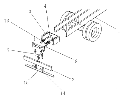
| No. | Part | What it does |
|---|---|---|
| 1 | Stringer | The vehicle chassis rail where the device mounts. |
| 2 | Rear bumper | The outer protective bar that contacts obstacles. |
| 3 | Pedestal | U-shaped base with side plates, bottom plate, and sliding slots. |
| 4 | Guide rod | Fixed to the bottom plate; guides the sliding block. |
| 5 | Sliding block | Slides in the pedestal slots; anchors the first telescopic rod. |
| 6 | First telescopic rod | Vertical link between the sliding block and the bumper. |
| 7 | Second telescopic rod | Diagonal link (bevel edge) between the bumper and bottom plate. |
| 8 | Spring | Pre-tightened on the second rod to provide force and return. |
| 9, 10 | Fixing seats | Pivot points connecting the second rod to the bumper and bottom plate. |
| 13 | Return spring | Mounted on the guide rod to pull the sliding block back. |
| 14, 15 | Idler wheel and base | Rollers extending below the bumper for ground contact. |
Operating steps
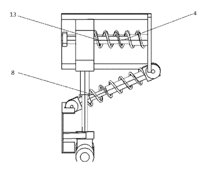
- Normal driving - the spring (8) holds the adjustable right-angled triangle in its default shape, keeping the rear bumper (2) at the designed height.
- Contact with obstacle - when reversing, the idler wheels (14) touch the obstacle first. The force pushes the bumper upward and inward.
- Linkage adjustment - the first telescopic rod (6) and second telescopic rod (7) shorten. The sliding block (5) moves forward along the guide rods (4) and slots. The triangle’s shape changes, lifting the bumper over the obstacle.
- Energy absorption - the pre-tightened spring (8) on the second rod compresses, absorbing the impact energy.
- Return - once the vehicle moves forward away from the obstacle, the spring (8) and the return spring (13) push the sliding block back, restoring the triangle to its original shape and lowering the bumper.
Applications
Loading docks and warehouses
Delivery trucks reverse into docks daily. Uneven dock plates or raised thresholds strike rigid bumpers. This assembly lets the bumper ride up over the threshold lip, preventing metal deformation on both the truck and the dock infrastructure.
Urban delivery routes
City trucks frequently park against high curbs. Standard bumpers scrape or bend when the driver misjudges the distance. The idler wheels roll against the curb while the telescopic rods absorb the displacement, reducing maintenance costs for fleet operators.
Construction and job sites
Utility vehicles operate on unpaved, rutted ground. A fixed bumper digs into mounds of dirt or debris when reversing. The adjustable triangle frame allows the bumper to lift over these irregularities without transferring shock loads to the chassis stringer.
Waste collection and municipal trucks
Refuse trucks stop and reverse hundreds of times per shift, often near concrete barriers or uneven pavement. The spring-loaded mechanism provides passive compliance, reducing the jarring impacts transmitted to the vehicle frame and extending the service life of the rear guard.
Where it is less suitable
- Passenger cars and light SUVs - the U-shaped pedestal and exposed linkage are sized for commercial stringers, not unibody passenger car frames.
- High-speed aerodynamic applications - the external rollers and telescopic rods create drag and do not fit flush bodywork designs.
- Vehicles requiring integrated electronic sensors - the patent describes a purely mechanical linkage; radar or camera integration requires separate brackets not covered here.
Frequently asked questions
How does the bumper lift over obstacles?
When the idler wheels hit an obstacle, the force pushes the bumper inward. The first and second telescopic rods shorten, and the sliding block moves forward in the pedestal. The right-angled triangle formed by the rods changes shape, raising the bumper. The pre-tightened spring absorbs the energy and returns the assembly to its starting position once the obstacle clears.
Will this fit my truck model?
The patent describes mounting to a vehicle stringer using a U-shaped pedestal. The pedestal dimensions, bolt patterns, and rod lengths are set in design to match specific chassis profiles. You will need to provide your stringer dimensions for a custom fit.
Do the idler wheels touch the ground while driving?
The patent states the bottom end acting surface of the idler wheel extends downward past the rear bumper. Whether they contact the ground during normal driving depends on the installed height and suspension travel, which are confirmed on prototypes.
What materials are used?
The patent text does not specify exact materials. For commercial truck applications, the pedestal, guide rods, and telescopic sleeves are typically fabricated from structural steel, while the rollers may be steel or polyurethane. Material selection is confirmed in design.
Does it require electrical power or sensors?
No. The entire mechanism relies on mechanical linkages, sliding blocks, and springs. It operates passively based on physical contact with obstacles.
Can the spring tension be adjusted?
The patent mentions a pre-tightened spring mounted on the second telescopic rod. The spring rate and preload are determined during the engineering phase to suit the vehicle’s weight class and intended use environment.
Can this design be made and sold in the US?
This patent was filed only in China and has no US or other foreign counterpart, so it does not restrict making or selling the design in the US. However, it remains in force in China until at most 2036-11-23 (if annual fees are paid), meaning production in China requires the owner’s permission. Because vehicle bumper and underride guard systems are heavily patented worldwide, a freedom-to-operate review is recommended before volume production. See Patent & Production.
Are you affiliated with the patent owner?
No. IP2M is an independent design and manufacturing service working from the public patent document.
Request a quote
Click Request a Quote below to see our email address - copy it, or open your email app with a ready-made message. Please mention patent CN106347272B in the subject.
Helpful details to include:
- Your company and channel (truck body builder, fleet operator, aftermarket parts brand, wholesaler)
- Vehicle class and stringer dimensions
- Target ground clearance and required stroke length
- Estimated quantity and timeline
- Required finish (e.g., hot-dip galvanized, powder coated)
- Regulatory needs (e.g., FMVSS No. 224 compliance)
You can also reach us at (332) 203-9997.
Explore this product
Interested in building this?
Tell us your target market, quantity and timeline. We reply with options for prototyping, small-batch runs or volume production.
Send your inquiry to
Please put CN106347272B in the subject line and tell us your company, country, estimated quantity and timeline.
Prefer to talk? Call (332) 203-9997.
More product-ready patents
All Car Accessories patents →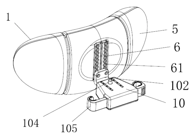
Car Accessories
Car Headrest Pillow with Ratchet Side Wings and Push-Button Reach
Post-mounted car headrest pillow with ratchet side wings and a push-button forward adjustment.
Patent CN212195197U
Car Accessories
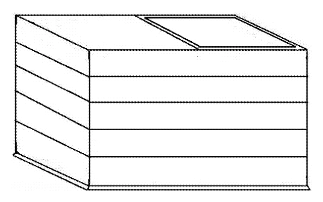
Hard-Shell Rooftop Tent That Doubles as a Cargo Box
Roof box whose hard frames lift on gas struts into a tent with door and skylight, and fold back for luggage.
Patent CN206327275U
Car Accessories
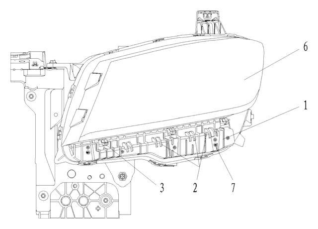
Headlamp-to-Bumper Adapter Bracket That Sets Gap and Flush in Three Directions
Molded bracket under the headlamp: support blocks and snap teeth locate the bumper flange for an even gap.
Patent CN216580316U
Car Accessories
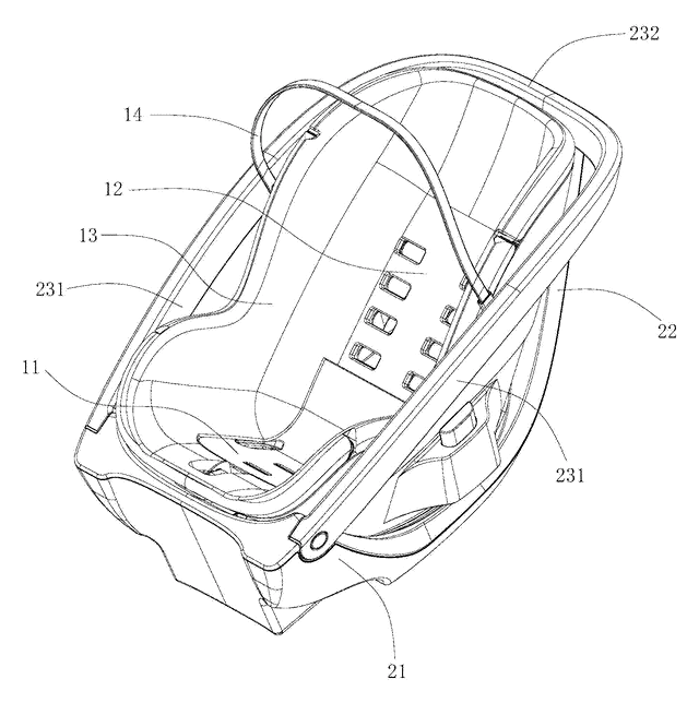
Infant Car Seat with a Load-Bearing Base That Wraps the Carrier
Infant car seat whose base has a backrest and swing-up side rails, so the carrier can be lighter.
Patent CN206383856U
Car Accessories
Retractable Side Impact Protection Block for Child Car Seats
Retractable side-impact block for child seats: springs out to provide side-impact buffering, folds flat.
Patent CN207028930U
Car Accessories
Rain-Deflecting Side Mirror with a Pivoting Air-Guide Plate
Side mirror with a top air duct and folding guide plate that directs airflow across the glass.
Patent CN207345672U
Browse by category
- Apparel & Accessories (22)
- Baby & Kids (16)
- Bags & Luggage (9)
- Bath & Personal Care (16)
- Car Accessories (10)
- Furniture, Bedding & Storage (12)
- Garden & Outdoor (18)
- Health & Wellness (8)
- Home, Kitchen & Cleaning (24)
- Lighting (12)
- Packaging & Containers (6)
- Pet Products (6)
- Phone & Camera Accessories (4)
- Retail Display (13)
- School, Office & Art (19)
- Sports & Recreation (25)
- Tools & Workshop (27)
- Toys & Games (12)
This page is based on the public patent document CN106347272B, assigned to Anhui Jianghuai Automobile Group Corp. IP2M is an independent manufacturing service and is not affiliated with, endorsed by or licensed by the patent owner. Images marked as concept renderings are illustrations, not photos of an existing product. Patent status information is provided for reference only and is not legal advice; confirm freedom to operate for your market before production. Full disclaimer.