At a glance
| Patent number | CN106347272B (application CN201611042127) |
| Type | China invention patent (发明专利) - protects product shape, structure and method |
| Original title | Vehicle rear protecting (车辆后防护) |
| Patent owner | Anhui Jianghuai Automobile Group Corp |
| Inventors | Liu Congcong, Liu Jiehao, Zhang Wei, Ma Xiaoyu, Zhou Liexin, Tian Yongliang, Hu Jie, Li Yingying, Wu Changqing |
| Filing date | 2016-11-23 |
| Grant date | 2018-12-14 |
| Status (China) | In force in China until at most 2036-11-23 (if annual fees are paid) |
| Patent family | Chinese filings only - no US, European, Japanese, PCT or other filings listed |
| Cited by | 1 later document |
| Source | Google Patents (search for CN106347272B) |
What the claims cover, in plain language
Claim 1 - a vehicle rear protecting device mounted on the tail of a stringer, comprising a rear bumper; a U-shaped pedestal with a side plate and a bottom plate, where the side plate is fixed to the stringer and has a sliding slot along its inner lateral edge; guide rods fixed to the bottom plate; a sliding block located between the side plates, sliding in the slots, with via holes for the guide rods; a first telescopic rod connecting the sliding block to the rear bumper; an oblique guide part comprising a second telescopic rod and a spring, where one end of the second rod is rotatably connected to the top of the bumper and the other to the bottom plate, with the spring pre-tightened between them. The first rod, second rod, and sliding slot surround an adjustable right-angled triangle, with the second rod as the bevel edge. It further includes idler wheels on roller fixing bases mounted at the back of the bumper, extending downward.
Claim 2 - adds a return spring pre-tightened on the guide rod between the sliding block and the bottom plate. Claim 3 - specifies an open slot in the bumper bottom for a first fixing seat connected to the second rod, and a fixing groove in the bottom plate for a second fixing seat. Claim 4 - states the fixing seats have parallel limit planes against which the spring rests. Claim 5 - connects the bottom end of the first telescopic rod to the idler wheel fixing base. Claim 6 - defines the telescopic rods as having a fixing sleeve with a first inside flange and a motion bar with a second flange that interlock. Claim 7 - specifies the sliding slot is formed by bending the side plate ends inwards into a T-type structure matching the sliding block.
This is a simplified reading for orientation only. The legal scope is defined by the exact claim wording in the official Chinese document.
What this means for US production
This patent was filed only in China and is currently in force in China until at most 2036-11-23 (if annual fees are paid). Making or selling this specific rear bumper guard design in China needs the owner’s permission. There is no US or other foreign counterpart.
Two points to settle early:
- Other patents may exist. Vehicle bumper and underride guard systems are widely patented globally. For example, 한국도로공사 (Korea Expressway Corporation) holds a later South Korean patent (KR102525105B1) citing this document in the same field. A freedom-to-operate (FTO) review covering adjustable bumper linkages and underride guards is needed before tooling for the US market.
- Load rating and stroke length. The dimensions of the telescopic rods, the spring rate, and the pedestal thickness must be calculated for the specific gross vehicle weight rating (GVWR) and expected impact forces. These values are set in design and confirmed on prototypes.
Customization and manufacturing
What can be customized
| Area | Options |
|---|---|
| Pedestal size | Width and depth to match specific truck stringer profiles |
| Telescopic rods | Stroke length and sleeve diameter to be confirmed in design |
| Spring rate | Pre-tightening force selected based on target vehicle weight class |
| Idler wheels | Roller diameter, width, and material (e.g., steel, polyurethane) |
| Finish | Hot-dip galvanizing, powder coating, or e-coating for corrosion resistance |
| Mounting interface | Bolt hole patterns customized to OEM chassis specifications |
Things to plan for (US market)
- FMVSS No. 224 / 49 CFR 571.224 - Rear impact guard (underride guard) standards for trailers and certain trucks; any bumper serving as an underride guard must meet static strength requirements.
- CMVSS 223 / 224 - Canadian equivalent standards if distributing in North America broadly.
- SAE J2603 - Testing procedures for rear underride guards, relevant if marketing for heavy-duty commercial use.
How a project runs
- Inquiry - vehicle class, stringer dimensions, required ground clearance, and quantity.
- Design - engineering the pedestal, selecting spring rates, sizing telescopic rods, and defining roller geometry.
- Prototype - machining or fabricating samples for fitment checks and functional testing on a test rig.
- Pilot run - durability cycling, salt spray testing for finishes, and load verification.
- Production - stamping pedestals, machining sleeves and rods, winding springs, molding rollers, and final assembly.
Quantities & timeline
The pedestal requires heavy-gauge stamping dies or laser cutting and welding fixtures. The telescopic rods need precision tube machining and flanging operations. Springs are custom-wound to the specified rate. Certification tests for FMVSS compliance, if applicable, add significant lead time. Send us your vehicle class, stringer dimensions, target ground clearance, estimated quantity and timeline and we will reply with options.
Patent drawings
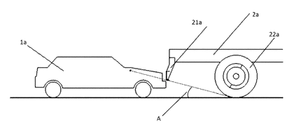
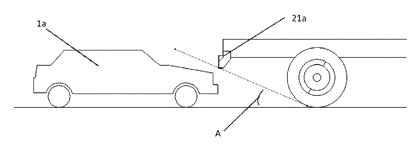
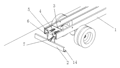
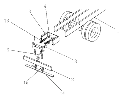
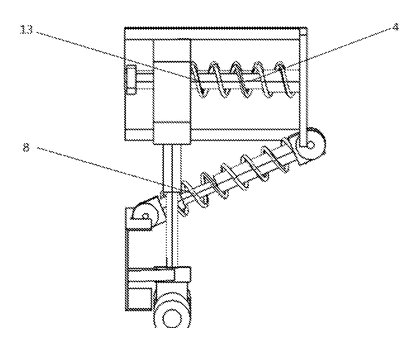
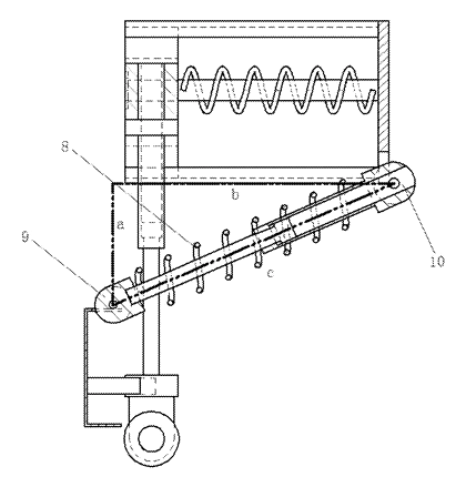
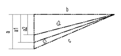
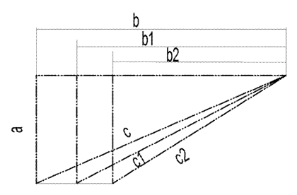
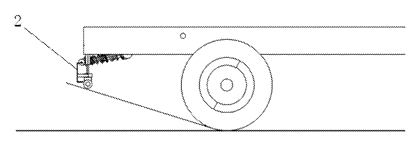
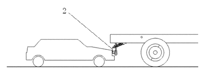
Drawings reproduced from the public patent document for reference.