
Patent CN106545770B
Updated October 28, 2026Adjustable Flashlight with a Vertically Reciprocating Light Source Assembly
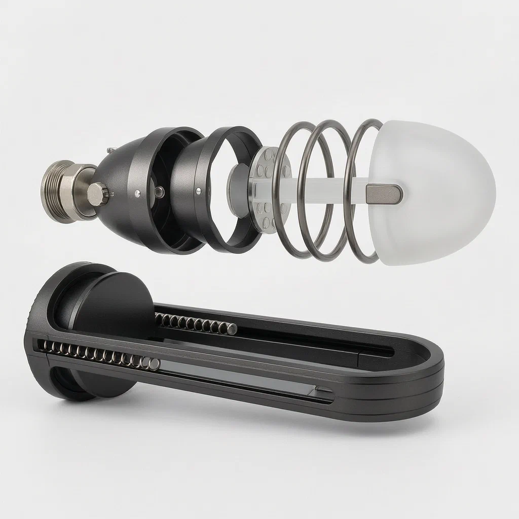
Most flashlights offer a fixed distance between the LED and the lens, so the beam pattern stays the same unless you twist the entire head. This design separates the light-emitting tube and the diffuser cover, mounting both on a vertical slide rail so they can move independently up and down. Magnetic rings on their facing surfaces control the spacing: rings with opposite polarity pull the parts together, while rings with the same polarity push them apart to hold a set gap. A spring inside the rail supports the assembly, and a rotating nut on a threaded rod lets the user lock it at the chosen height. The result is a portable light whose beam spread can be adjusted by moving internal components rather than turning the outer shell.
- China invention patent - in force
- No filings outside China
- Portable lighting
- Magnetic spacing, polycarbonate diffuser
Splat! What let you down?
🔦
Vertical adjustment
The light-emitting tube and diffuser slide up and down on a rail instead of a twist-focus barrel.
🧲
Magnetic spacing
Rings on the tube and diffuser attract or repel to set the gap between them.
🔩
Spring and nut lock
A spring inside the rail supports the parts; a rotating nut on a threaded rod holds the height.
💡
Matched diameters
A fixing ring on the tube opening matches the diffuser diameter for alignment.
Bring this product to market
- ✓ Patent vetted China-only family and legal status checked
- 2 Product brief · now How it works, uses and options written up
- 3 Prototype First samples for buyers to review
- 4 Pilot run Small first batch for launch customers
- 5 Volume production Repeat orders at scale
Buyer interest
– of 100 buyers needed to start prototyping
One click, no sign-up. Each vote is one real visitor, and products with the most interest go to prototyping first.
Build team: no members yet. Need a partner, co-funding or skills to build this? Join and we introduce the team once it forms.
The problem
Standard flashlights change their beam pattern by twisting the head to move the reflector relative to the LED. That motion relies on external threads that collect dust, wear out after repeated use, and require two hands to adjust smoothly. When the housing is wet or the user wears gloves, gripping and turning the bezel becomes difficult. Additionally, because the lens and the light source move together as one unit, fine control over the distance between the emitter and the diffuser is limited to the pitch of the outer threads. Users who need a precise beam spread for close-up tasks versus long-range illumination often find the steps too coarse or the mechanism too stiff to operate quickly.
The solution
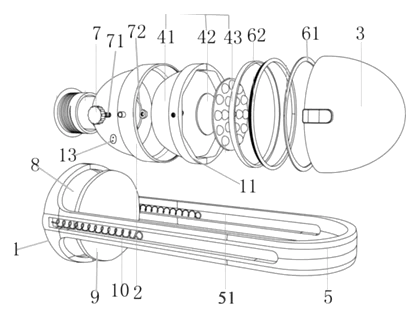
This flashlight places the light-emitting tube and the diffuser cover on an internal vertical slide rail mounted on a lamp holder above a base. Instead of twisting the outer shell, the user adjusts the position of the components along the rail.
- A slide rail is provided on the lamp holder, oriented vertically above the base.
- Both the light-emitting tube and the diffuser cover are slidably arranged on this rail, allowing independent up-and-down movement.
- Magnetic rings are fitted on the opposing faces of the tube and the diffuser. When the rings carry different magnetic properties, they attract and the parts sit in contact; when they carry the same properties, they repel and maintain a gap.
- A fixing ring sleeved on the outer contour of the tube’s opening has a diameter that matches the diffuser, keeping the parts aligned during travel.
- A spring sits inside the slide rail, with one end fixed to the base and the other end sleeved on a threaded rod.
- A rotating nut on the threaded rod secures the assembly at the desired height.
- A light-transmitting sheet, described as a circular sheet, is part of the optical path.
Who it is for
- Outdoor gear brands seeking a flashlight with a smooth, thread-free focus mechanism for camping and hiking customers.
- Industrial and maintenance suppliers that sell work lights to technicians who adjust beam spread while wearing gloves.
- Amazon private-label sellers looking for a distinct portable lighting product with a visible mechanical difference from standard twist-focus models.
- Wholesale distributors supplying hardware stores with task lighting that offers repeatable height settings via the nut lock.
How it works
The main parts
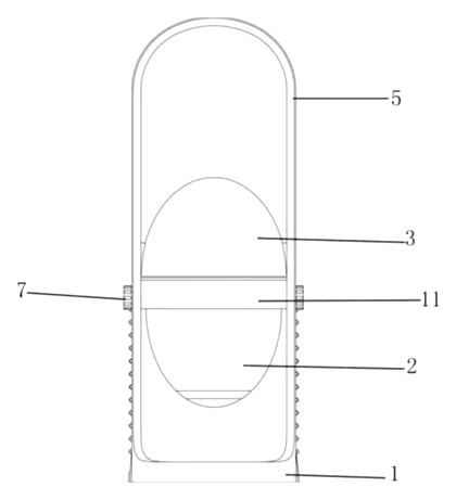
| No. | Part | What it does |
|---|---|---|
| 1 | Base | Supports the lamp holder and anchors the spring. |
| 2 | Light-emitting tube | Houses the light source; slides on the rail. |
| 3 | Diffuser cover | Spreads the light; slides on the rail. Made of polycarbonate plastic. |
| 51 | Slide rail | Vertical track on the lamp holder guiding the tube and diffuser. |
| 62 | Magnetic rings | Mounted on opposing sides of the tube and diffuser to attract or repel. |
| 7 | Rotating nut | Threads onto the rod to lock the assembly height. |
| 71 | Threaded rod | Runs through the spring and nut. |
| 9 | Light-transmitting sheet | Circular sheet in the optical path. |
| 10 | Spring | Inside the rail; one end on the base, other on the rod. |
| 11 | Fixing ring | Sleeved on the tube opening; diameter matches the diffuser. |
Operating steps
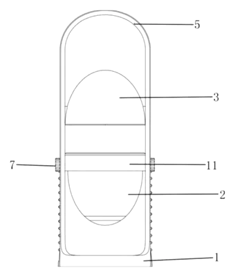
- Release the lock - turn the rotating nut on the threaded rod to free the assembly.
- Slide the components - push or pull the light-emitting tube and diffuser along the vertical rail. The spring provides bias.
- Magnetic interaction - if the magnetic rings have the same polarity, they repel, holding the diffuser away from the tube at a set gap. If they have opposite polarity, they attract and the parts rest in contact.
- Lock the height - tighten the rotating nut against the rod to fix the position.
- Align - the fixing ring ensures the tube opening and the diffuser stay concentric throughout the travel.
Applications
Night hiking and trail walking
Hikers switch between a wide flood beam for reading maps and a narrow spot for the trail ahead. The vertical slide allows this change without twisting a stiff bezel with cold hands.
Workshop and repair tasks
Mechanics working under vehicles need a broad wash of light, then a focused beam for bolt inspection. The nut lock holds the exact position so the beam does not drift while the light is set down.
Power outage and emergency kits
Households store flashlights for emergencies where quick, intuitive operation matters. Sliding parts with magnetic feedback are easier to explain and use than threaded heads.
Photography and video fill light
Content creators sometimes use small continuous lights to fill shadows. Adjusting the diffuser distance changes the softness of the light without adding external modifiers.
Where it is less suitable
- Tactical or law-enforcement use - operators typically require silent, instant toggle switches and ruggedized bodies without exposed threaded rods.
- Deep-water diving - the open slide rail and threaded rod would need extensive sealing beyond what the patent describes.
- Ultra-compact keychain lights - the vertical rail and spring mechanism add length, making it unsuitable for pocket-sized micro-lights.
Frequently asked questions
How does the beam adjustment work without twisting the head?
The light-emitting tube and the diffuser cover slide up and down on a vertical rail inside the lamp holder. Moving them along the rail changes the distance between the light source and the diffuser, altering the beam spread.
What do the magnetic rings do?
They control the spacing between the tube and the diffuser. If the rings have opposite magnetic properties, they attract and the parts touch. If they have the same properties, they repel and hold a gap. This gives tactile feedback during adjustment.
Is the diffuser made of glass?
No. According to claim 4 of the patent, the material of the diffuser cover is polycarbonate plastic.
How is the height locked in place?
A spring sits inside the slide rail, and a threaded rod passes through it. A rotating nut on the rod tightens against the assembly to hold it at the selected height.
What powers the flashlight?
The patent describes the mechanical and optical structure but does not specify the battery type or capacity. The power source compartment size is set in design and confirmed on prototypes.
Can the magnetic rings fall out if dropped?
The patent states the rings are provided on the opposite sides of the tube and diffuser. In production, they must be encapsulated or press-fitted securely to withstand drop impacts, which is verified during prototype testing.
Can this design be made and sold in the US?
The patent was filed only in China and is in force there until at most 2036-10-24 (if annual fees are paid), meaning manufacturing in China requires the owner’s permission. There is no US counterpart, but portable lighting is a heavily patented category. We recommend a freedom-to-operate check before volume production - see Patent & Production.
Are you affiliated with the patent owner?
No. IP2M is an independent design and manufacturing service working from the public patent document.
Request a quote
Click Request a Quote below to see our email address - copy it, or open your email app with a ready-made message. Please mention patent CN106545770B in the subject.
Helpful details to include:
- Your company and channel (outdoor brand, Amazon seller, industrial supplier, wholesale distributor)
- Target dimensions and preferred body material
- Battery type (rechargeable cell or standard alkaline sizes)
- Magnetic behavior preference (repelling gap or attracting contact)
- Estimated quantity and target price
- Timeline - when you would like samples and the first shipment
You can also reach us at (332) 203-9997.
Explore this product
Interested in building this?
Tell us your target market, quantity and timeline. We reply with options for prototyping, small-batch runs or volume production.
Send your inquiry to
Please put CN106545770B in the subject line and tell us your company, country, estimated quantity and timeline.
Prefer to talk? Call (332) 203-9997.
More product-ready patents
All Lighting patents →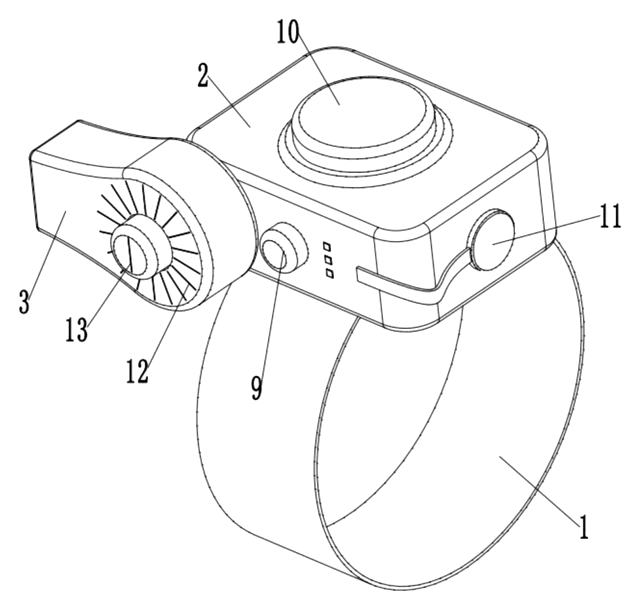
Lighting
Wrist-Worn Flashlight with Click-Lock Angle Adjustment
Rechargeable wrist flashlight whose lamp turns and locks at an angle with a push button.
Patent CN113915544B
Lighting
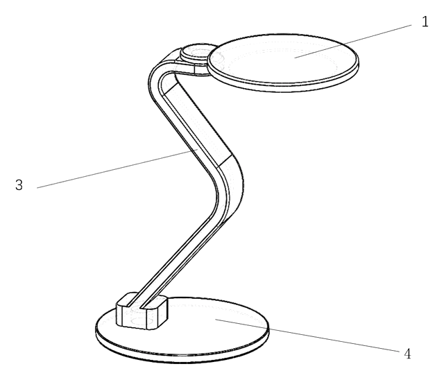
Self-Folding Desk Lamp That Turns into a Phone Stand
Desk lamp with a shape-memory stem that unfolds when warm and folds into a phone stand.
Patent CN213237087U
Lighting
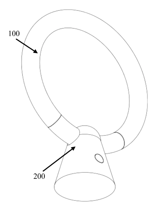
Ring-Shaped Outdoor Lantern That Lifts Off a Power-Bank Charging Base
Ring lantern with a battery handle that docks in a cone base with its own battery, clamp and charging plug.
Patent CN212408329U
Lighting
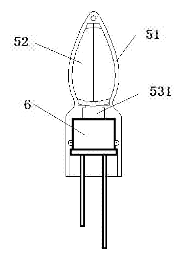
LED Flameless Candle with an Outside Flame Shade and Wax Dish Top
Battery LED candle: flame shade stands above a dished wax top, angled LEDs light a printed wick.
Patent CN205424561U
Lighting
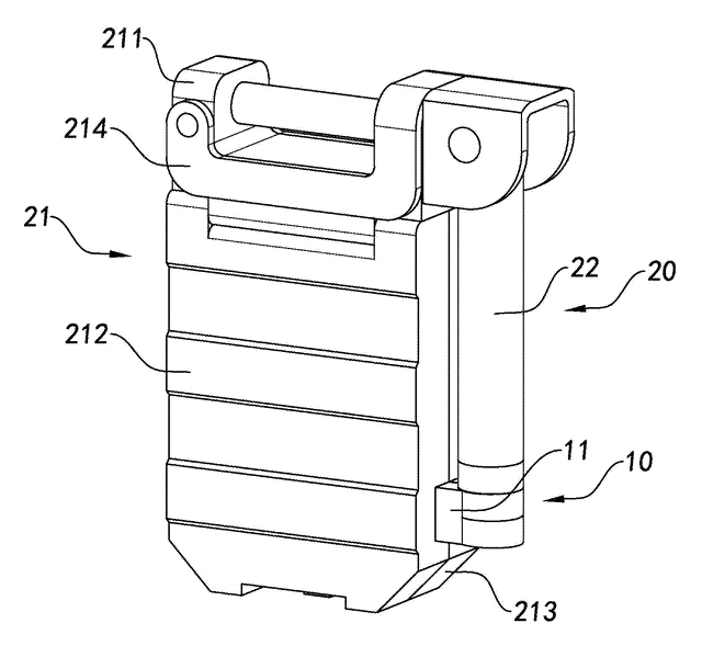
Telescoping Tripod Portable Work Light with Fold-In Light Panels
Telescoping tripod work light with dual light panels that fold flat into the base.
Patent CN207298471U
Lighting
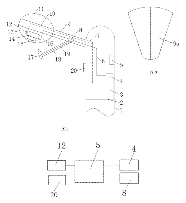
Self-Cooling and Self-Cleaning LED Street Light with Rainwater Harvesting
LED street lamp that harvests rain to cool its heat sink and spray-wash the lens automatically.
Patent CN205480639U
Browse by category
- Apparel & Accessories (22)
- Baby & Kids (16)
- Bags & Luggage (9)
- Bath & Personal Care (16)
- Car Accessories (10)
- Furniture, Bedding & Storage (12)
- Garden & Outdoor (18)
- Health & Wellness (8)
- Home, Kitchen & Cleaning (24)
- Lighting (12)
- Packaging & Containers (6)
- Pet Products (6)
- Phone & Camera Accessories (4)
- Retail Display (13)
- School, Office & Art (19)
- Sports & Recreation (25)
- Tools & Workshop (27)
- Toys & Games (12)
This page is based on the public patent document CN106545770B, assigned to Guanxian Anchang Information Technology Service Co ltd, Shanghai Chengkang Intellectual Property Service Co ltd. IP2M is an independent manufacturing service and is not affiliated with, endorsed by or licensed by the patent owner. Images marked as concept renderings are illustrations, not photos of an existing product. Patent status information is provided for reference only and is not legal advice; confirm freedom to operate for your market before production. Full disclaimer.