
Patent CN107150741B
Updated October 27, 2026Hydraulic Dropper Seatpost with a Self-Contained Lifting Adjustment Unit
Conventional dropper seatposts route their oil circuits across multiple separate parts, making repairs time-consuming and exposing internal seals to sideways forces every time a rider sits down. This design moves the entire oil circuit exchange into one self-contained lifting adjustment unit. Inside the unit, a valve seat at the bottom of the inner tube carries several axial valve ports at eccentric positions and a central port. An oil baffle plate sits directly above the valve seat, blocking the ports in a vertical, up-and-down arrangement rather than sliding sideways against them. Because the baffle plate is pushed straight down by an elastic body instead of being dragged laterally, it avoids the shear stress that wears out conventional seals when the rider's weight presses on the saddle. The result is a longer service life for the sealing components. Maintenance is also simpler: if the post develops a fault, the mechanic replaces the single lifting adjustment unit instead of tracing leaks through scattered channels. The outer wall of the lower joint seat and the bottom end inner wall of the outer pipe are sealed and fixed together, keeping the assembly compact.
- China invention patent - in force
- No filings outside China
- Bicycle accessories
- Modular lifting unit, hydraulic oil circuit
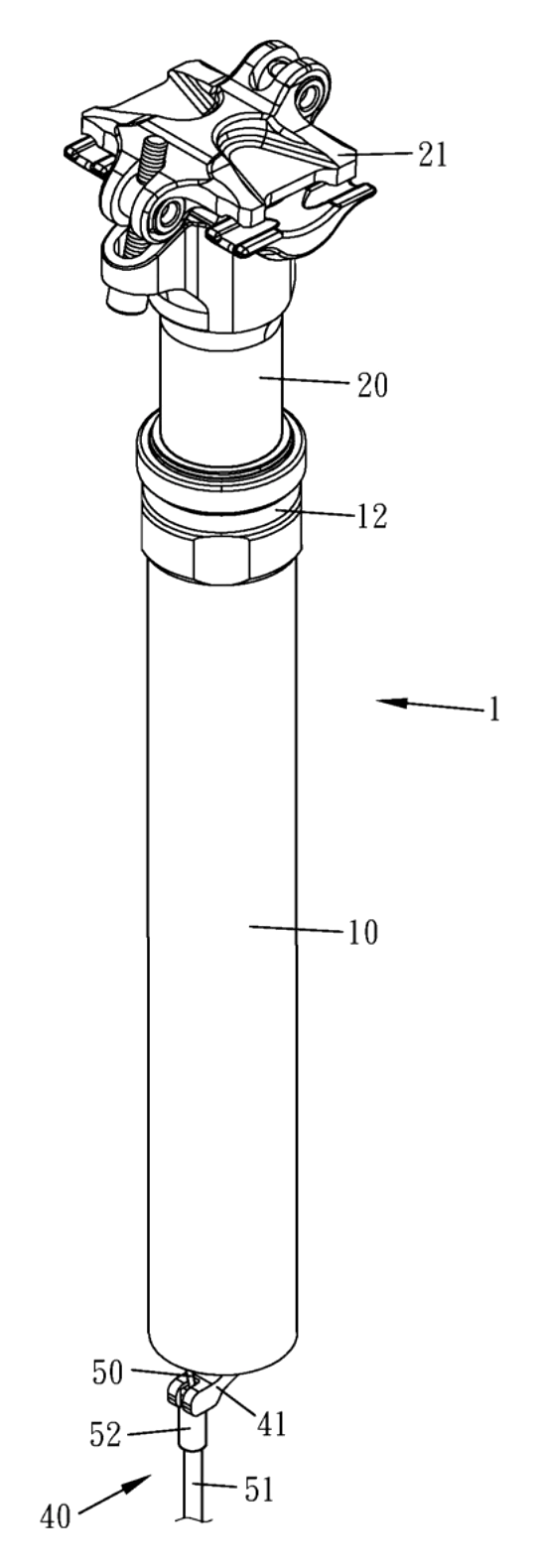
Splat! What let you down?
🔧
Self-contained unit
All oil circuit exchange is located inside one lifting adjustment unit, simplifying repair and assembly.
⬇️
Vertical baffle fit
The oil baffle plate blocks the valve ports in an up-and-down setting, improving the sealing effect.
🛡️
Reduced shear stress
The baffle plate avoids lateral shear forces when the rider sits down, increasing service life.
🚲
Cable actuated
A control arm below the collision surface routes a standard cable for remote lever operation.
Bring this product to market
- ✓ Patent vetted China-only family and legal status checked
- 2 Product brief · now How it works, uses and options written up
- 3 Prototype First samples for buyers to review
- 4 Pilot run Small first batch for launch customers
- 5 Volume production Repeat orders at scale
Buyer interest
– of 100 buyers needed to start prototyping
One click, no sign-up. Each vote is one real visitor, and products with the most interest go to prototyping first.
Build team: no members yet. Need a partner, co-funding or skills to build this? Join and we introduce the team once it forms.
The problem
On a typical hydraulic dropper seatpost, the oil passages that control height adjustment run through several separate components. When a seal fails or the oil degrades, a mechanic must disassemble the entire post, trace the leak path, and replace individual rings or cartridges spread across the length of the tube. This takes time and requires specific knowledge of each brand’s layout. Furthermore, conventional designs often place the sealing element so that it slides laterally against a port when the rider’s weight presses down on the saddle. That sideways shear stress gradually cuts into the seal material, leading to oil bypass, slow sinking under load, and premature failure. Brands and wholesalers dealing with warranty returns face high labor costs when every service call means a full teardown rather than a quick swap.
The solution
This mechanism solves both issues by consolidating the hydraulics and changing how the valve closes.
- One lifting adjustment unit – The entire oil circuit exchange takes place inside a single module made up of a first tube (outer) and a second tube (inner) passing through it. If the mechanism needs servicing, the whole unit is replaced as one piece.
- Up-and-down valve fit – At the bottom of the inner tube, a valve seat holds several valve ports at eccentric positions and a central port in the middle. An oil baffle plate sits directly above this seat.
- Vertical blocking – Instead of sliding sideways, the baffle plate is pushed downward by an elastic body so its outer diameter covers the valve ports from above. This vertical arrangement provides a firm block.
- Shear-free loading – Because the baffle plate meets the valve seat straight down, the rider’s weight does not drag the plate laterally across the ports. The seal faces compression rather than shear, which extends its working life.
- Sealed joints – An upper joint seat seals the top ends of both tubes, while a lower joint seat seals the bottom of the first tube. The outer wall of the lower joint seat and the bottom inner wall of the outer pipe are sealed and fixed together.
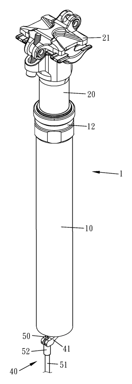
Who it is for
- Bicycle component brands looking for a dropper seatpost design that reduces warranty returns by eliminating shear-prone seals and simplifying field service.
- Bike assembly factories that want faster production lines; replacing a single lifting unit during quality checks is quicker than bleeding a multi-part hydraulic circuit.
- Wholesalers and distributors supplying aftermarket suspension seatposts to bike shops, where mechanics value a drop-in cartridge replacement over a full rebuild.
- E-bike manufacturers whose heavier frames and riders place more constant load on the seatpost, benefiting from a seal arrangement that resists shear wear.
How it works
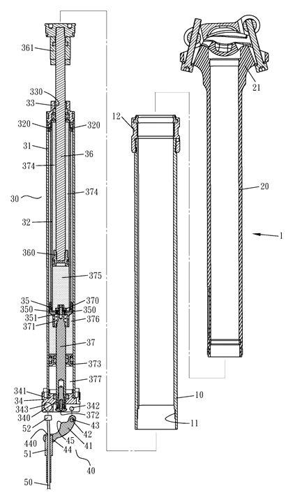
The main parts
| No. | Part | What it does |
|---|---|---|
| 31 | First tube (outer pipe) | Houses the inner tube and forms the outer structure of the lifting unit. |
| 32 | Second tube (inner pipe) | Passes through the first tube; carries the piston and valve seat. |
| 33 | Upper joint seat | Combines with the top nozzles of both tubes and seals the top end. |
| 34 | Lower joint seat | Fixed to the bottom end nozzle of the first tube; has an upper port, a lower port, and a fixing hole for the pivot shaft. |
| 35 | Valve seat | Fixed to the bottom end of the second tube; contains eccentric valve ports and a central port. |
| 36 | Shaft rod | Passes through the upper opening; fixed to a base inside the inner tube so they move axially together. |
| 37 | Striker | Its top passes through the central port to connect to the oil baffle plate; its bottom has a striking surface that extends through the lower port. |
| 370 | Oil baffle plate | Located above the valve seat; pushed down by an elastic body to block the valve ports vertically. |
| 360 | Piston | Fixed to the end of the shaft rod inside the second tube; contacts the inner wall of the second tube. |
| 373 | Floating piston | Sheathed on the striker in the middle section of the first tube; pushed axially. |
| 41 | Control arm | Pivots on the lower joint seat below the striking surface; accepts the control cable. |
Operating steps
- Rider pulls the remote lever – The cable pulls the control arm, which pivots on the shaft hole at the eccentric position of the lower joint seat.
- Striker moves – The control arm pushes the striking surface of the striker upward through the lower port.
- Baffle lifts – The striker’s top, fixed to the oil baffle plate, raises the plate off the valve seat, unblocking the eccentric valve ports.
- Oil flows – With the ports open, oil squeezed in the third oil chamber flows through the oil through holes on the outer wall of the second tube into the first oil chamber. The inner tube can now slide relative to the outer tube, lowering or raising the saddle.
- Lever released – The elastic body pushes the oil baffle plate back down onto the valve seat, blocking the ports vertically and locking the height.
Applications
Mountain biking on technical trails
Riders frequently change saddle height between climbs and descents. A mechanism that locks firmly without lateral seal wear handles repeated drops throughout a ride. When a trail-side issue occurs, swapping the single lifting unit gets the rider back faster than bleeding separate chambers.
E-bikes and commuter bikes
Heavier e-bikes put sustained static loads on the seatpost while stopped at lights or parked. The vertical baffle arrangement resists the slow creep caused by shear stress on conventional seals, keeping the saddle at the set height.
Bike rental and fleet operations
Rental shops service dozens of bikes weekly. A modular lifting unit means staff replace one cartridge instead of rebuilding complex internals, cutting turnaround time between customers.
Endurance and gravel riding
Long-distance riders encounter mixed surfaces and spend hours in the saddle. Reduced internal friction from the up-and-down valve fit allows smoother transitions when adjusting posture on variable terrain.
Where it is less suitable
- Ultralight road racing – Road racers rarely adjust saddle height mid-ride and prioritize absolute minimum weight; a rigid carbon seatpost remains lighter than any hydraulic mechanism.
- BMX or fixed-gear park riding – These disciplines do not use adjustable-height seatposts, so the mechanism offers no benefit.
- Lowest-budget city bikes – The precision machining required for the valve seat, floating piston, and sealed joint seats places this above basic quill-style posts in cost.
Frequently asked questions
Why is the lifting adjustment unit described as self-contained?
According to the patent, the entire oil circuit exchange is located inside the lifting adjustment unit. This means the hydraulic pathways do not run through separate external parts. When repairing the seatpost, only this single unit needs to be replaced, which simplifies assembly and maintenance.
How does the oil baffle plate seal the valve?
The patent describes an up-and-down fitting relationship between the valve ports on the valve seat and the oil baffle plate. An elastic body pushes the baffle plate downward so its outer diameter covers the eccentric valve ports. This vertical blocking action provides the oil baffle effect.
What is the advantage of avoiding shear stress?
In conventional designs, sitting on the seat cushion drags the sealing element sideways against the ports. According to the patent, because this mechanism uses a vertical fit, the oil baffle plate is not subjected to that lateral shear stress when a person sits on the seat cushion, which increases the service life of the component.
How is the height adjusted by the rider?
A control arm is located below the striking surface of the striker. The patent describes a pivot shaft passing through a shaft hole on the control arm and into a fixing hole on the lower joint seat. A control cable is routed through a line hole in the insert groove of the control arm. Pulling the cable pivots the arm, moving the striker and lifting the baffle plate off the valve ports to allow oil to flow and the post to move.
What travel lengths and diameters are available?
The patent does not list specific sizes. Outer diameters and stroke lengths are set in design and confirmed on prototypes to match standard bicycle frame seat tubes.
Does the mechanism use air or oil?
The patent describes a first oil chamber, a second oil chamber, and a third oil chamber filled with oil, as well as an air chamber with air inside located between the floating piston and the lower joint seat.
Can this design be made and sold in the US?
The patent was filed only in China and is in force in China until at most 2036-03-02 (if annual fees are paid). It has no US counterpart, so it does not restrict the design in the United States. However, dropper seatposts are covered by other active patents in the US, so a freedom-to-operate check is recommended before volume production. See Patent & Production.
Are you affiliated with the patent owner?
No. IP2M is an independent design and manufacturing service working from the public patent document.
Request a quote
Click Request a Quote below to see our email address - copy it, or open your email app with a ready-made message. Please mention patent CN107150741B in the subject.
Helpful details to include:
- Your company and channel (bicycle component brand, e-bike manufacturer, wholesaler, or bike assembly factory)
- Target outer diameters and desired travel / stroke lengths
- Actuation preference (cable routing direction)
- Material and finish requirements for the outer tube
- Estimated quantity and target price
- Timeline - when you would like prototypes and the first shipment
You can also reach us at (332) 203-9997.
Explore this product
Interested in building this?
Tell us your target market, quantity and timeline. We reply with options for prototyping, small-batch runs or volume production.
Send your inquiry to
Please put CN107150741B in the subject line and tell us your company, country, estimated quantity and timeline.
Prefer to talk? Call (332) 203-9997.
More product-ready patents
All Sports & Recreation patents →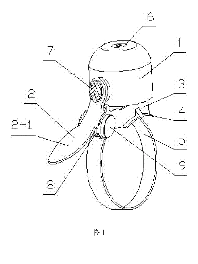
Sports & Recreation
Compact Torsion-Spring Bike Bell
Mini bike bell with a standard torsion spring and a rubber-floated dome - small size, clear tone, quick strap mount.
Patent CN205819384U
Sports & Recreation
Padded Toe-Box Shield for Sneakers
Ventilated, silicone-lined toe-box insert that supports the front of a sneaker and cushions the toes.
Patent CN209473731U
Sports & Recreation
Reversible Fishing Seat-Box Lid with Backrest
Fishing seat-box lid that flips on removable hinge pins: cushion, backrest and storage on one face.
Patent CN208624426U
Sports & Recreation
Swivel-Pin Skateboard Truck with Rubber Sleeve
Skateboard truck with a turning center pin, a tilting axle clamp and a rubber sleeve that centers it.
Patent CN216777880U
Sports & Recreation
Full-Face Bike Helmet with Magnetic Detachable Chin Bar
Full-face cycling helmet whose chin bar clips on and off with magnetic, latching side connectors.
Patent CN206630067U
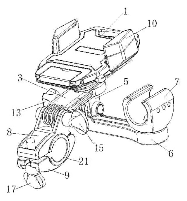
Sports & Recreation
Bike Phone Holder with Built-In Flashlight Clamp
Handlebar mount with a phone cradle on top and a flashlight clamp below, on one arm.
Patent CN206077485U
Browse by category
- Apparel & Accessories (22)
- Baby & Kids (16)
- Bags & Luggage (9)
- Bath & Personal Care (16)
- Car Accessories (10)
- Furniture, Bedding & Storage (12)
- Garden & Outdoor (18)
- Health & Wellness (8)
- Home, Kitchen & Cleaning (24)
- Lighting (12)
- Packaging & Containers (6)
- Pet Products (6)
- Phone & Camera Accessories (4)
- Retail Display (13)
- School, Office & Art (19)
- Sports & Recreation (25)
- Tools & Workshop (27)
- Toys & Games (12)
This page is based on the public patent document CN107150741B, assigned to Taiwan Hodaka Industrial Co Ltd. IP2M is an independent manufacturing service and is not affiliated with, endorsed by or licensed by the patent owner. Images marked as concept renderings are illustrations, not photos of an existing product. Patent status information is provided for reference only and is not legal advice; confirm freedom to operate for your market before production. Full disclaimer.