At a glance
| Patent number | CN107150741B (application CN201610116461) |
| Type | China invention patent (发明专利) - protects product shape, structure and method |
| Original title | Height adjusting mechanism for bicycle seat tube (自行车座管高度调整机构) |
| Patent owner | Taiwan Hodaka Industrial Co Ltd |
| Inventors | Cai Yingxin |
| Filing date | 2016-03-02 |
| Grant date | 2019-03-19 |
| Status (China) | In force in China until at most 2036-03-02 (if annual fees are paid) |
| Patent family | Chinese filings only - no US, European, Japanese, PCT or other filings listed |
| Cited by | 0 later documents |
| Source | Google Patents (search for CN107150741B) |
What the claims cover, in plain language
Claim 1 describes the core lifting adjustment unit. It includes a first tube and a second tube passing through it. An upper joint seat combines the top nozzles of both tubes, and a lower joint seat fixes to the bottom of the first tube, sealing it. Both joint seats have central ports. A valve seat is fixed to the bottom of the second tube, containing several eccentric valve ports and a central port. A shaft rod passes through the upper opening and connects to a piston inside the second tube. A striker passes through the central port of the valve seat and connects to an oil baffle plate above it. The baffle plate is larger than the valve port positions and is pushed down by an elastic body to block them in an up-and-down fit. The striker’s bottom has a striking surface extending through the lower port. A floating piston sits on the striker in the first tube. The spaces form a first oil chamber, second oil chamber, third oil chamber, and an air chamber. Oil through holes on the second tube allow oil to flow from the third to the first chamber.
Claim 2 adds the control arm located below the striking surface. One end has a shaft hole pivoting on a fixing hole at the eccentric position of the lower joint seat. The other end has an insert groove with a notch facing away from the striking surface, a line hole, and a corresponding line head hole on the lower joint seat for routing a control cable.
This is a simplified reading for orientation only. The legal scope is defined by the exact claim wording in the official Chinese document.
What this means for US production
This patent was filed only in China and is currently in force in China until at most 2036-03-02 (if annual fees are paid). It has no US or other foreign counterpart. Making or selling this exact mechanism in China needs the owner’s permission while the patent remains in force.
Two points to settle early:
- Other patents may exist. The dropper seatpost market is covered by numerous active patents held by major cycling component companies regarding hydraulic circuits, air-spring return systems, and cable routing. A freedom-to-operate (FTO) review of the specific valve-seat geometry, baffle-plate arrangement, and cartridge layout is recommended before committing to tooling.
- Travel length and diameter. The stroke of the inner tube and the outer diameters of the first and second tubes determine the mold sizes for different frame standards (e.g., 30.9 mm, 31.6 mm). These dimensions must be set in design and confirmed on prototypes.
Customization and manufacturing
What can be customized
| Area | Options |
|---|---|
| Outer diameter | Sizes to match standard bicycle seat tubes (to be confirmed in design) |
| Travel / stroke | Different drop lengths by altering the tube overlap and shaft rod travel |
| Actuation | Cable routing direction via the insert groove on the control arm |
| Materials | Aluminum alloy or steel for the tubes; elastomer or spring for the elastic body |
| Surface finish | Anodizing, hard coat, or painted finishes for the outer tube |
| Seal compounds | Oil-compatible O-rings and wipers selected for the chosen hydraulic fluid |
Things to plan for (US market)
- CPSC 16 CFR 1512 – Requirements for bicycles and bicycle components sold in the US, covering structural integrity.
- ISO 4210 – International safety standard for bicycles; many US buyers require testing to its fatigue and static load clauses for seatposts.
- California Prop 65 – Anodized metals, lubricants, and elastomers must be screened for listed chemicals.
How a project runs
- Inquiry – Target diameters, travel lengths, actuation style, and volume.
- Design – Tube wall thickness, valve port sizing, baffle plate diameter, and joint seat profiles.
- Prototype – Machined samples to verify the up-and-down baffle fit, oil flow rate, and shear-stress reduction.
- Pilot run – Fatigue cycling, static load tests, and temperature range checks for the hydraulic fluid and seals.
- Production – Tube extrusion or drawing, CNC machining of joint seats and valve seats, stamping of the control arm, assembly, oil filling, and bleed.
Quantities & timeline
Manufacturing requires deep-drawing or extrusion dies for the first and second tubes, precision CNC fixtures for the valve seat and joint seats, and injection molds if polymer components are used for the baffle plate or control arm guides. Filling and bleeding the oil chambers adds a dedicated assembly step. Certification testing per ISO 4210 takes additional weeks. Send us your target diameters, travel lengths, actuation preference, estimated quantity and target price and we will reply with options.
Patent drawings
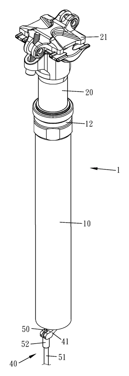
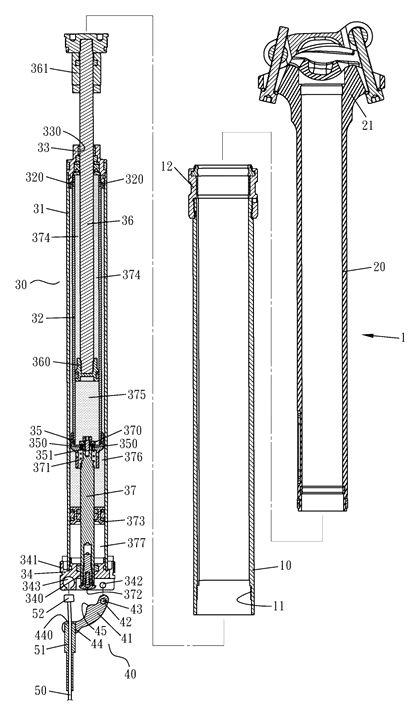
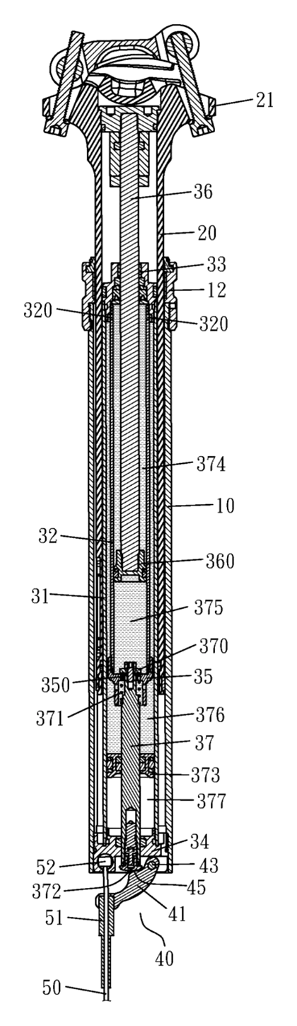
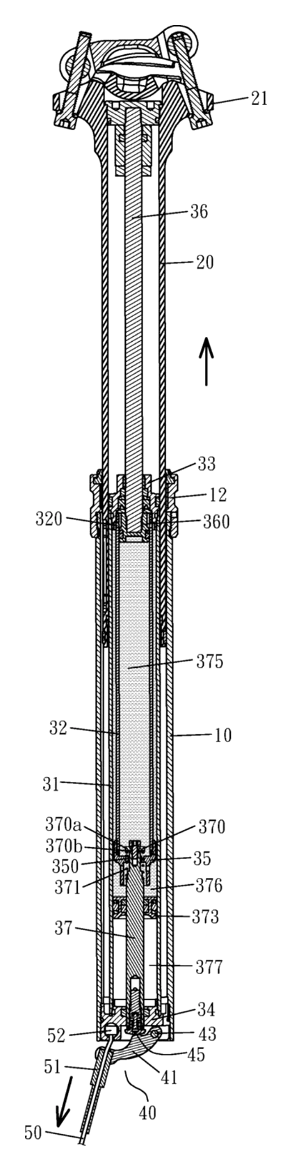
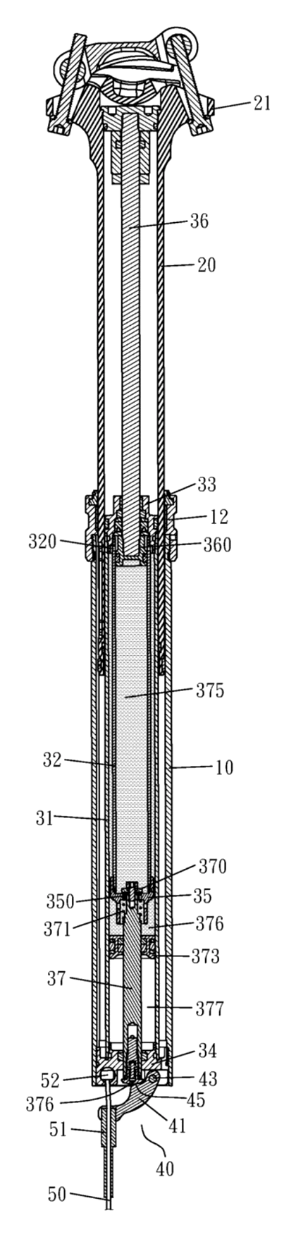
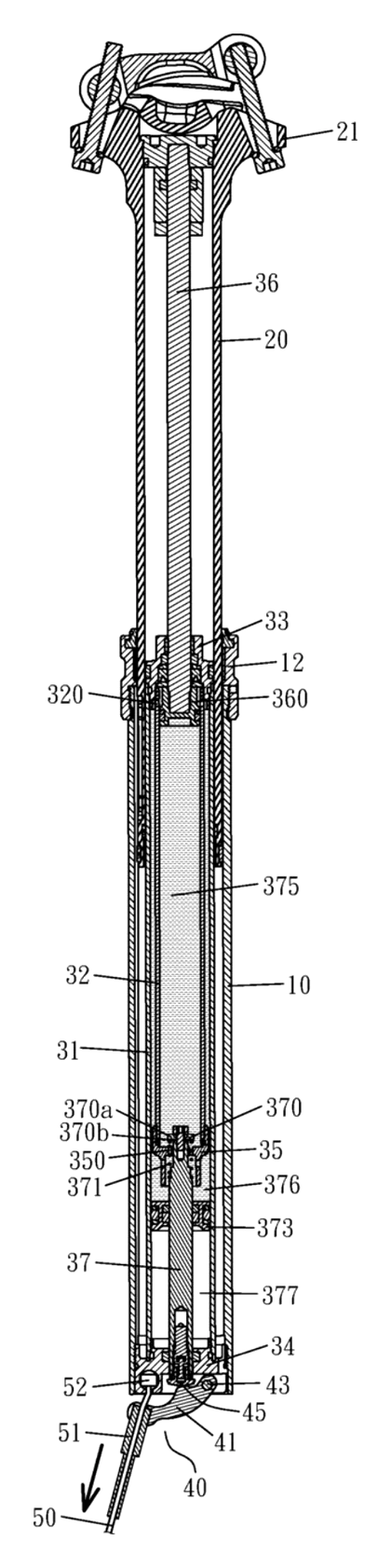
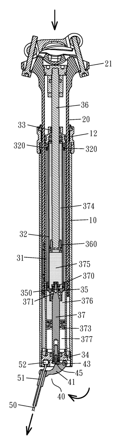
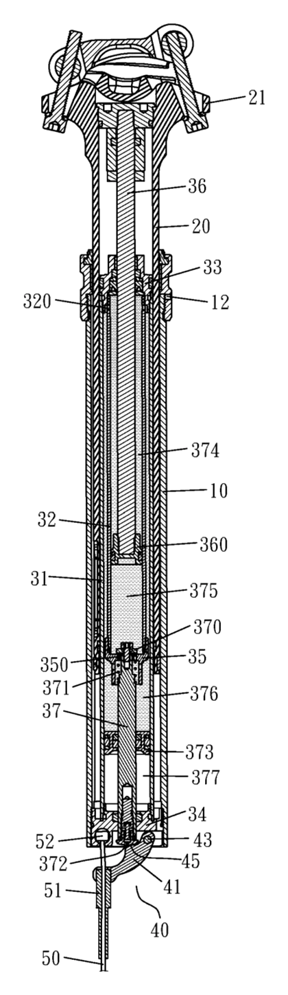
Drawings reproduced from the public patent document for reference.