
Patent CN107183868B
Updated November 7, 2026Umbrella Frame with Adjustable Canopy Span via Screw-Driven Hinge Mechanism
Standard umbrellas require forceful pushing to open and pulling to close, often straining wrists and damaging hinges. This patent describes a mechanism where turning a single knob adjusts the entire canopy's span. By using a screw-driven vertical movement coupled with rotating hinge blocks, the rib assembly expands or folds smoothly. The X-shaped linkage ensures all ribs move in unison, providing a stable and adjustable shelter that can be fine-tuned for wind resistance or coverage area with minimal effort.
- China invention patent - lapsed
- No filings outside China
- Outdoor gear & accessories
- Threaded rod, hinge blocks, X-linkage ribs
Splat! What let you down?
🔩
Screw-driven adjustment
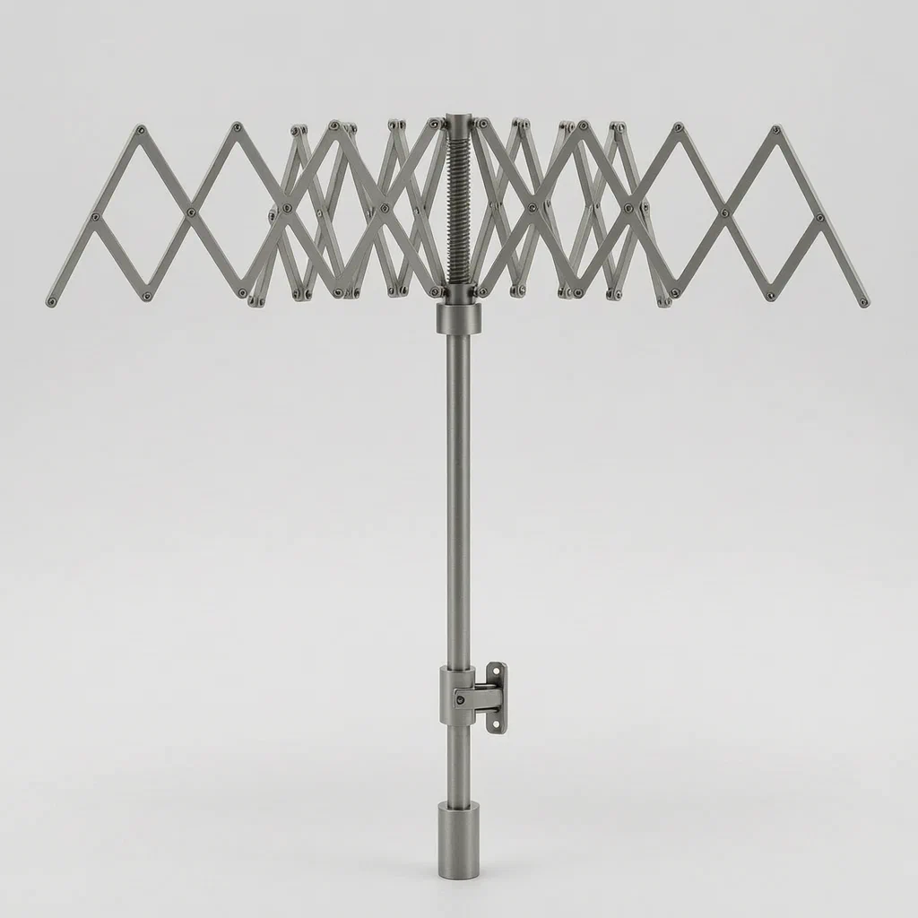
A nut block on a threaded rod controls the canopy expansion; no forceful pushing required.
🔄
Rotating hinge blocks
Hinge blocks rotate on the nut as it moves, changing the angle of the rib linkages smoothly.
📐
X-shaped folding units
Linked rods form X-units that expand into an arc, ensuring all ribs move in sync.
🎯
Variable shielding range
Users can fine-tune the umbrella size for wind stability or maximum coverage.
Bring this product to market
- ✓ Patent review Patent family and legal status reviewed in the relevant jurisdictions.
- 2 Product brief · now How it works, uses and options written up
- 3 Prototype First samples for buyers to review
- 4 Pilot run Small first batch for launch customers
- 5 Volume production Repeat orders at scale
Buyer interest
– of 100 buyers needed to start prototyping
One click, no sign-up. Each vote is one real visitor, and products with the most interest go to prototyping first.
Build team: no members yet. Need a partner, co-funding or skills to build this? Join and we introduce the team once it forms.
Patent Rights & Team Participation
Before joining a development team, participants should ensure they have the necessary rights or authorization to participate in the project.
Participation is generally appropriate where:
- You own the relevant patent rights or have obtained permission or a license from the rights holder.
- The relevant patent rights have expired or have been legally invalidated in the jurisdictions where the planned activities will take place.
- The planned development, manufacturing, and commercialization activities have been independently assessed and do not infringe applicable patent rights in the relevant jurisdictions.
Important: Being located outside a country where a patent is protected does not automatically exempt you from patent infringement risks. Patent rights may apply based on where development, manufacturing, use, sale, or import activities take place.
IP2M does not grant any patent license or authorization through team participation. Joining a project does not provide permission to use, manufacture, or commercialize patented technology.
The problem
Traditional umbrellas rely on a sliding runner that forces ribs outward against spring tension. This requires significant hand strength to open and can strain the wrist when closing. Furthermore, once fully extended, the canopy size is fixed. In high winds, users cannot reduce the surface area to improve stability, and in light rain, they cannot shrink the canopy to avoid blocking views or catching too much wind. Manual adjustment of individual ribs is impractical and fragile.
The solution
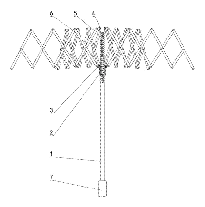
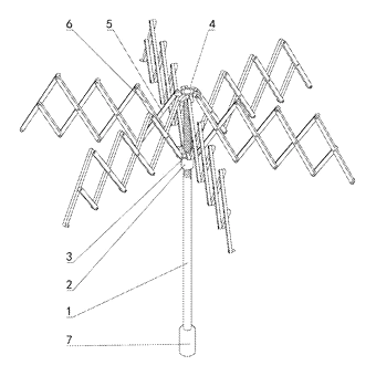
- A support rod (1) serves as the central spine, with its upper part threaded.
- A nut operation block (2) screws onto the threaded section. Turning this block moves it vertically along the rod.
- A hinged block (3) is sleeved onto the nut operation block and can rotate around the nut’s axis.
- An X-shaped folding unit connects the hinged block to a connecting block (4) at the top of the rod. This unit consists of a first connecting rod (5) and a second connecting rod (6).
- Multiple folding units are linked sequentially to form the umbrella rib unit.
- When the nut block is turned, it moves up or down. Because the hinged block rotates relative to the nut while moving, the distance between the top and bottom pivot points of the X-units changes. This causes the entire rib assembly to expand outward (opening) or fold inward (closing) in a controlled, synchronized motion.
Who it is for
- Outdoor gear brands looking for differentiated mechanisms for wind-resistant or adjustable-size umbrellas.
- Accessibility product designers creating easy-to-operate umbrellas for users with limited grip strength.
- Promotional merchandise manufacturers seeking unique functional features for branded gifts.
- High-end fashion accessory makers who value mechanical elegance and smooth operation over standard plastic runners.
How it works
The main parts
| No. | Part | What it does |
|---|---|---|
| 1 | Support rod | Central shaft with threads on the upper section. |
| 2 | Nut operation block | Screws onto the rod; vertical movement drives the system. |
| 3 | Hinged block | Sits on the nut; rotates as the nut moves, transferring motion to ribs. |
| 4 | Connecting block | Fixed at the top of the rod; anchors the outer ends of the ribs. |
| 5, 6 | First and second connecting rods | Form the X-shaped linkage; change angle to expand/collapse ribs. |
| 7 | Handle | Attached to the lower end of the support rod for holding. |
Opening and closing
- Turn the nut block: Rotating the nut operation block (2) causes it to travel up or down the threaded support rod (1).
- Rotate the hinge: The hinged block (3), which rides on the nut, rotates relative to the nut due to the geometry of the linkages.
- Change the angle: As the hinged block moves vertically and rotates, the distance between its connection point and the top connecting block (4) changes.
- Expand the ribs: The X-shaped units flatten out, pushing the rib tips outward to increase the canopy diameter. Closing reverses this process, folding the ribs inward.
Applications
Wind-resistant personal umbrellas
In gusty conditions, users can partially close the canopy to reduce drag and prevent inversion, then reopen it when the wind dies down.
Accessible outdoor gear
The screw mechanism requires twisting rather than pushing, making it easier for elderly users or those with arthritis to operate compared to traditional snap-open umbrellas.
Compact travel umbrellas
The synchronized folding action allows for a tighter closed profile, as the ribs nest neatly without protruding hardware, ideal for small bags.
Garden and patio shade structures
Adapted for larger scale, this mechanism could adjust the span of portable shade umbrellas to match sun angles throughout the day.
Where it is less suitable
- Extreme heavy-duty industrial use - The threaded mechanism may wear faster under constant vibration or heavy loads compared to simple slide runners.
- Low-cost mass market items - The precision required for the screw and hinge assembly increases manufacturing complexity and cost.
- Automatic opening models - Integrating a spring-loaded auto-open feature with this specific screw-driven geometry requires additional complex engineering not described in the patent.
Patent & Production
At a glance
| Patent number | CN107183868B (application CN201710455314) |
| Type | China invention patent (发明专利) - protects method and structure |
| Original title | Umbrella Stand with Adjustable Shielding Range (一种可调整遮挡范围的伞架) |
| Patent owner | Individual |
| Inventors | Hou Jingwen |
| Filing date | 2017-06-16 |
| Grant date | 2018-03-20 |
| Status (China) | Lapsed - terminated for non-payment of annual fees (recorded 2026-06-12) |
| Patent family | Public record shows Chinese filings only - no US, European, Japanese, PCT or other filings listed |
| Cited by | 0 later documents |
| Source | Google Patents (search for CN107183868B) |
What the claims cover, in plain language
Claim 1 - An umbrella stand with adjustable shielding range comprising a support rod (1). The upper part of the rod has threads. A nut operation block (2) screws onto these threads. A hinged block (3) is set on the nut block and can rotate along the nut’s axis. The top of the rod has a connecting block (4). One side of the connecting block has a first connecting rod (5), hinged to the block. The hinged block (3) has a second connecting rod (6), hinged to the first rod at their midpoints to form an X-shaped folding unit. The endpoints of the rods form an isosceles trapezoid shape. Multiple such units are connected sequentially to form the rib assembly. The connecting block holds multiple rib units distributed around the rod’s axis.
Claim 2 - The support rod (1) has a handle (7) installed at its lower end.
This is a simplified reading for orientation only. The legal scope is defined by the exact claim wording in the official Chinese document.
What this means for US production
This patent was filed in China and has lapsed, so it no longer restricts anyone in China either. The public record shows no US or other foreign counterpart.
Two points to settle early:
- Other patents may exist. Umbrella mechanisms are a crowded field with many active US patents covering various runner and rib geometries, so a freedom-to-operate (FTO) review of the screw-driven hinge concept is needed before tooling.
- Material selection. The patent does not specify materials for the threads or hinges; durability depends on metal choice and lubrication, which must be validated in prototypes.
Customization and manufacturing
What can be customized
| Area | Options |
|---|---|
| Rod material | Aluminum alloy, steel, or fiberglass core |
| Thread pitch | Fine thread for precise adjustment, coarse for speed |
| Rib count | 6, 8, or more folding units per canopy |
| Canopy fabric | Polyester, pongee, nylon, or UV-coated materials |
| Handle design | Ergonomic grip, straight, or curved wood/plastic |
| Finish | Anodized aluminum, chrome plating, powder coating |
Things to plan for (US market)
- CPSC Safety Standards - General consumer product safety rules apply; sharp edges on the handle or exposed threads should be minimized.
- California Prop 65 - Metal finishes and plastics used in handles and ribs are screened for lead and phthalates.
- ASTM F963 - If marketed as a toy or for children, strict mechanical hazard tests apply.
- FCC Part 15 - Not applicable unless electronic sensors are added (not in patent).
How a project runs
- Inquiry - Specify desired canopy diameter, rib count, and target weight.
- Design - Finalize thread specs, hinge geometry, and material choices.
- Prototype - CNC machined or cast samples for fit and function testing.
- Pilot run - Small batch production to test assembly tolerances and durability.
- Production - Injection molding for plastic parts, extrusion for rods, assembly.
Quantities & timeline
Tooling for injection-molded hinge blocks and handles takes several weeks. Rod extrusion and threading are standard processes. Durability testing of the screw mechanism under cyclic load is critical. Send us your specifications, quantity, and target price and we will reply with options.
Production notes
Tooling and process
Injection molds are likely needed for the nut operation block and hinged block if plastic is chosen. Metal rods typically undergo cutting and threading. Assembly involves pressing or screwing components together.
Cost drivers
Precision machining of the threaded rod adds cost. Complex hinge geometries may require multi-cavity molds. Fabric grade and stitching density affect canopy costs.
Prototyping path
Start with 3D-printed or cast components to verify the kinematic motion. Sewn first samples allow checking canopy tension. Wear trials simulate long-term usage. The exact sequence depends on the final design and supplier feedback.
What we would change before tooling
We might refine the thread engagement length to prevent stripping. Adding a stopper mechanism could limit over-extension. Lubricant channels in the hinge bosses might improve longevity.
Common failure points
Thread wear from repeated adjustment is a risk. Hinge boss stress concentration could cause cracking. Sole delamination is not applicable here, but fabric tearing at rib tips is possible. Size deviation in molded parts affects fit.
Patent drawings
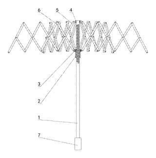
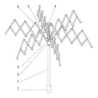
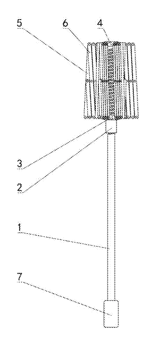
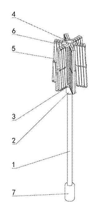
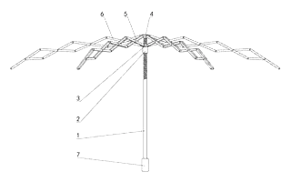
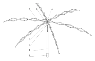
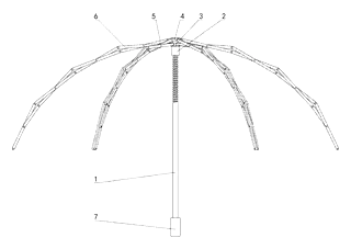
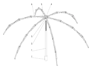
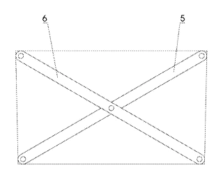
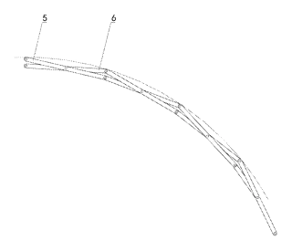
Drawings reproduced from the public patent document for reference.
Frequently asked questions
How does the adjustment work?
You turn the nut block on the threaded rod. As it moves up or down, it pushes the hinged blocks, which rotate and change the angle of the X-shaped ribs. This expands or collapses the canopy smoothly.
Is it harder to open than a normal umbrella?
It requires twisting instead of pushing. Some users find this easier on the wrist, especially if the traditional push-action is stiff. However, it is slower than a snap-open automatic model.
What happens if the threads wear out?
The patent does not specify materials. In production, we would use hardened steel or brass for the threads and add lubrication. Regular maintenance might be needed for very frequent use.
Can the canopy size be changed while walking?
Yes, you can turn the knob one-handed to slightly adjust the span, though it is best done when stationary to avoid dropping the umbrella.
Are there different sizes available?
The mechanism scales well. You can have small pocket umbrellas or large golf-style shades, provided the rod and ribs are sized appropriately for the load.
Does it work in strong wind?
The ability to reduce the canopy diameter helps in wind. However, the mechanical joints are more complex than simple slides, so extreme gusts could still stress the hinges.
Can this design be made and sold in the US?
The patent was filed in China and has lapsed, and the public record shows no US counterpart, so it does not restrict the design in the US or in China. Umbrella mechanisms may be covered by other US patents - see Patent & Production - so we recommend a freedom-to-operate check before volume production.
Are you affiliated with the patent owner?
No. IP2M is an independent design and manufacturing service working from the public patent document.
Request a quote
Click Request a Quote below to see our email address - copy it, or open your email app with a ready-made message. Please mention patent CN107183868B in the subject.
Helpful details to include:
- Your company and channel (outdoor brand, promotional gift supplier, retail chain)
- Desired canopy diameter and rib count
- Material preferences for rod, hinges, and fabric
- Target retail price and estimated quantity
- Timeline - when you would like samples and the first shipment
You can also reach us at (332) 203-9997.
Page editor: Emily Zhang, Product Editor · IP2M
Last updated November 7, 2026. If something on this page looks wrong, email [email protected] and we will check it against the patent.
Interested in building this?
Tell us your target market, quantity and timeline. We reply with options for prototyping, small-batch runs or volume production.
Send your inquiry to
Please put CN107183868B in the subject line and tell us your company, country, estimated quantity and timeline.
Prefer to talk? Call (332) 203-9997.
More product-ready patents
All Apparel & Accessories patents →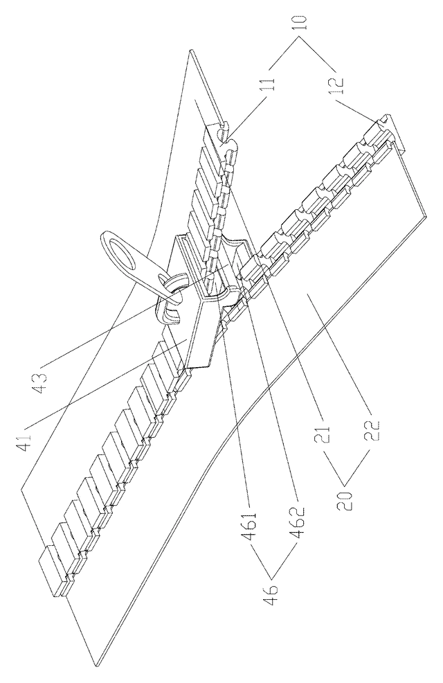
Apparel & Accessories
Stacked Zipper with Teeth That Mesh Top-to-Bottom
Zipper whose two identical tooth rows mesh on top of each other, closed by a simplified slider.
Patent CN205795062U
Apparel & Accessories
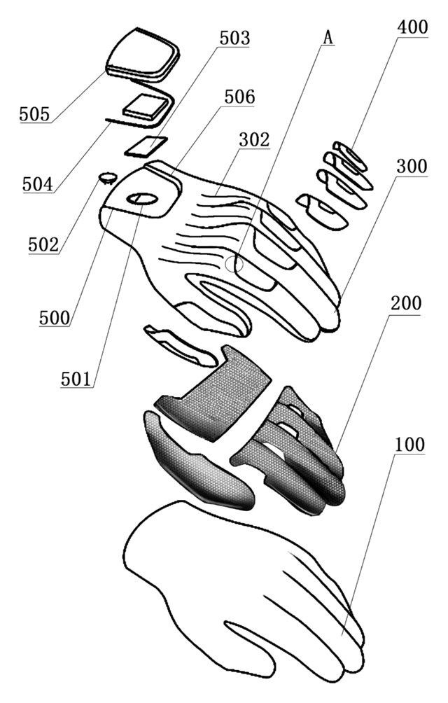
Impact-Resistant Glove with a 3D-Printed Lattice Layer
Work glove with a 3D-printed lattice impact layer, TPU knuckle guards and a light mounting area.
Patent CN213785583U
Apparel & Accessories
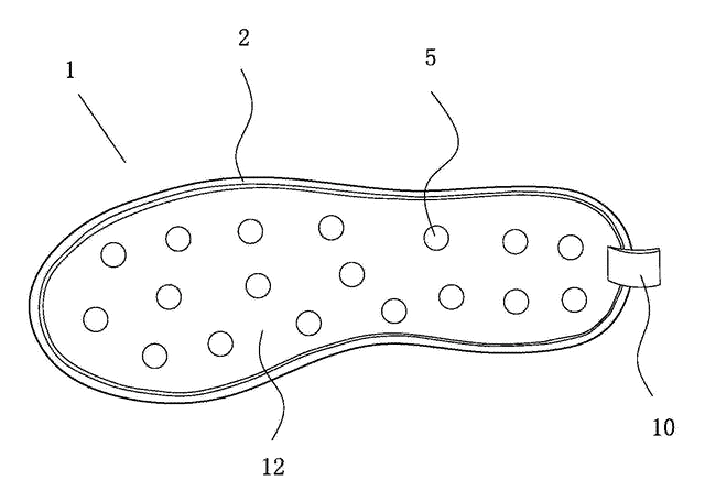
Massage Insole with Spring-Back Silicone Nubs and a Removable Top Layer
Layered insole: silicone nubs rise through a removable perforated top sheet and sink under each step.
Patent CN208286505U
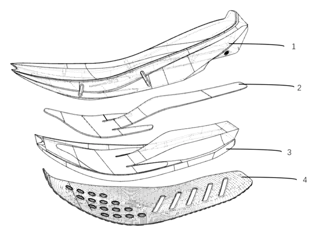
Apparel & Accessories
Heel-Less Carbon Plate Running Shoe Sole for Forefoot Strikers
Running sole for forefoot strikers: no ground-touching heel, winged carbon plate between two midsoles.
Patent CN216723354U
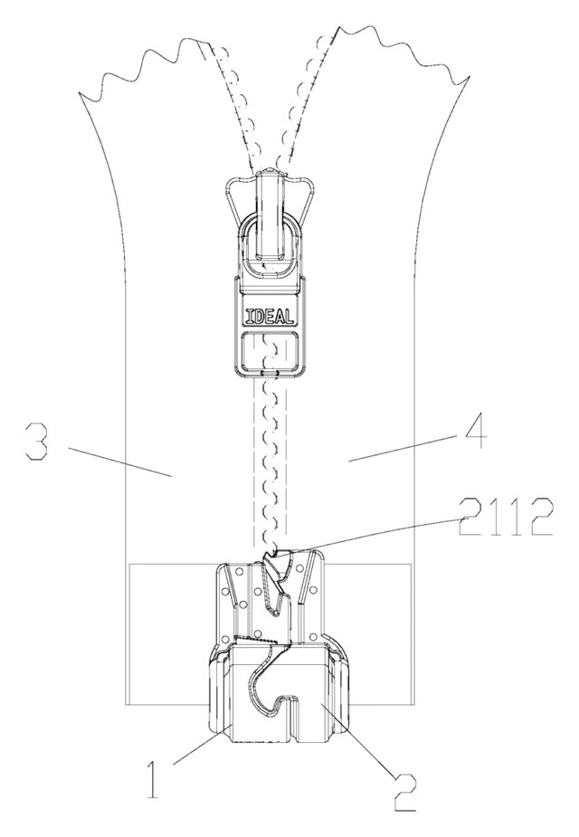
Apparel & Accessories
Waterproof Magnetic Zipper Stop That Snaps the Two Halves Together
Separating-zipper stop with sealed magnets: pin and box snap together one-handed, safe in rain and wash.
Patent CN215075936U
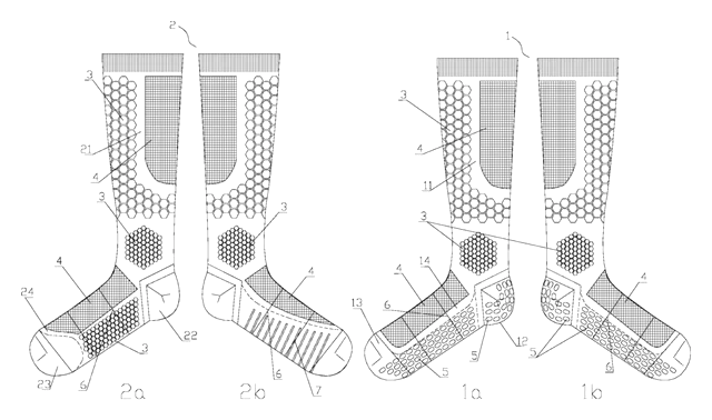
Apparel & Accessories
Left-Right Specific Soccer Socks: Grip for the Plant Foot, Touch Pads for the Kicking Foot
Soccer socks knitted as a left-right pair: grip zones for the plant foot, pads for the kicking foot.
Patent CN212728807U
Browse by category
- Apparel & Accessories (46)
- Baby & Kids (28)
- Bags & Luggage (17)
- Bath & Personal Care (30)
- Car Accessories (25)
- Furniture, Bedding & Storage (23)
- Garden & Outdoor (32)
- Health & Wellness (14)
- Home, Kitchen & Cleaning (48)
- Lighting (23)
- Packaging & Containers (12)
- Pet Products (11)
- Phone & Camera Accessories (9)
- Retail Display (25)
- School, Office & Art (35)
- Sports & Recreation (45)
- Tools & Workshop (54)
- Toys & Games (22)
This page is based on the public patent document CN107183868B, assigned to Individual. IP2M is an independent manufacturing service and is not affiliated with, endorsed by or licensed by the patent owner. Images marked as concept renderings are illustrations, not photos of an existing product. Patent status information is provided for reference only and is not legal advice; confirm freedom to operate for your market before production. Full disclaimer.