
Patent CN107487232B
Updated November 5, 2026Rear Seat Cushion Mounting Structure with Elastic Locking Buckle
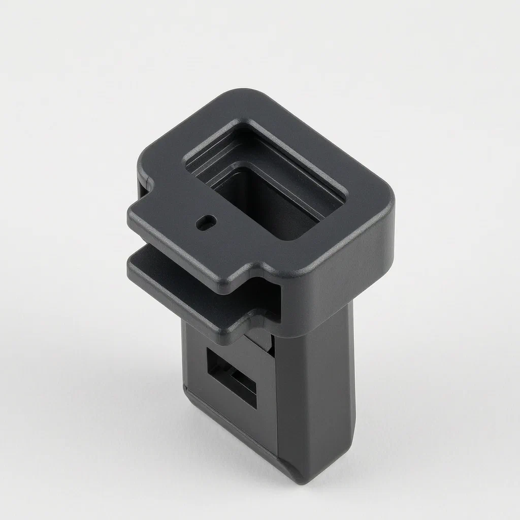
Traditional seat mounts often require bolts, specific tools, or complex latches that can strip threads or jam over time. This design replaces those mechanisms with a purely mechanical snap-lock. The core component is a fixing buckle consisting of a stationary body and a moving lock cylinder. The lock cylinder is built as a closed rectangular frame where one side acts as a spring (elastic deformation part) and the opposite side slides on rails. Wedge-shaped bosses protrude from the sliding side toward the center hole. These wedges have an inclined face for easy entry and a straight face for secure holding. The assembly sits in a groove on the vehicle floor. The seat cushion carries a simple U-shaped metal or plastic hook. Installation is a single downward press; removal is a single thumb push. This structure reduces part count and eliminates the need for threaded fasteners in high-vibration zones.
- China invention patent - lapsed
- No filings outside China
- Automotive interior hardware
- Elastic snap-lock mechanism, wedge guides
Splat! What let you down?
🔒
Snap-in installation
The seat cushion locks automatically when pressed down; no tools or bolts required.
👆
One-touch release
An exposed unlocking tab allows users to release the lock by pushing it, avoiding violent dismantling.
⚙️
Wedge-based locking
Sliding parts use inclined surfaces for easy entry and straight surfaces for rigid retention.
🛡️
Protected mechanism
Cover portions on the buckle body shield the internal sliding parts from debris and accidental contact.
Bring this product to market
- ✓ Patent review Patent family and legal status reviewed in the relevant jurisdictions.
- 2 Product brief · now How it works, uses and options written up
- 3 Prototype First samples for buyers to review
- 4 Pilot run Small first batch for launch customers
- 5 Volume production Repeat orders at scale
Buyer interest
– of 100 buyers needed to start prototyping
One click, no sign-up. Each vote is one real visitor, and products with the most interest go to prototyping first.
Build team: no members yet. Need a partner, co-funding or skills to build this? Join and we introduce the team once it forms.
Patent Rights & Team Participation
Before joining a development team, participants should ensure they have the necessary rights or authorization to participate in the project.
Participation is generally appropriate where:
- You own the relevant patent rights or have obtained permission or a license from the rights holder.
- The relevant patent rights have expired or have been legally invalidated in the jurisdictions where the planned activities will take place.
- The planned development, manufacturing, and commercialization activities have been independently assessed and do not infringe applicable patent rights in the relevant jurisdictions.
Important: Being located outside a country where a patent is protected does not automatically exempt you from patent infringement risks. Patent rights may apply based on where development, manufacturing, use, sale, or import activities take place.
IP2M does not grant any patent license or authorization through team participation. Joining a project does not provide permission to use, manufacture, or commercialize patented technology.
The problem
In many vehicles, rear seat cushions are secured using bolted brackets, complex latch assemblies, or friction-fit pins. Bolted systems require tools for removal, making seat folding or cleaning difficult for end-users. Complex latches involve multiple moving parts that can jam due to dirt accumulation or wear, leading to rattles or failure to lock. Friction fits may loosen over time due to vibration, causing the seat to shift unexpectedly during driving. There is a need for a mounting structure that allows quick, tool-free installation and removal while maintaining a rigid connection under load, minimizing part count and potential failure points.
The solution
The patent describes a fixing buckle and a mounting structure that solves these issues through a passive elastic snap-lock mechanism.
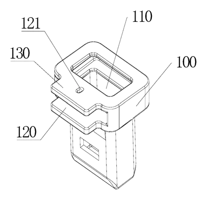
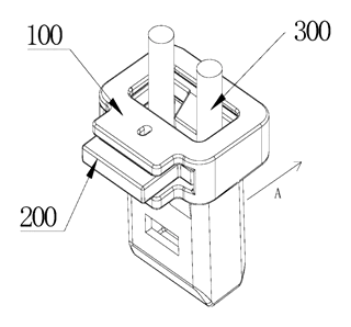
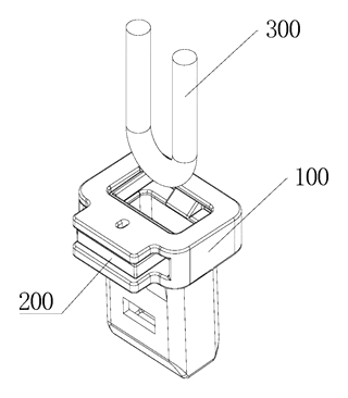
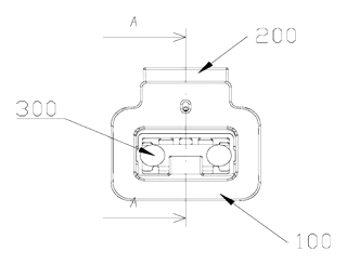
- The Buckle Body (100) is fixed to the vehicle’s bottom plate. It features a first opening (110) where the seat bracket enters and a second opening perpendicular to the first, housing the lock cylinder.
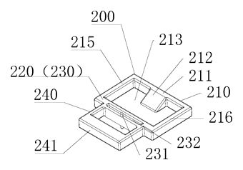
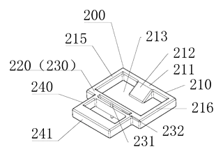
- The Lock Cylinder (200) is inserted into the buckle body. It consists of a sliding part (210) and an elastic deformation part (220) connected together to form a closed frame.
- The Sliding Part (210) moves within a sliding groove (120) on the buckle body. It includes wedge-shaped bosses (212) that protrude toward the central through-hole (213). These wedges guide the incoming bracket.
- The Elastic Deformation Part (220) acts as the spring. It is anchored to the side wall of the buckle body. When force is applied, this part deforms, allowing the sliding part to move backward.
- The Unlocking Part (240) is exposed at the second opening. It connects to the elastic part via driving arms. Pushing this part forces the elastic section to deform, moving the sliding part away from the locked position.
- The U-shaped Bracket (300) attached to the seat cushion serves as the “member to be locked.” It inserts into the buckle body, interacts with the wedges, and triggers the locking action.
Who it is for
- Automotive Interior Suppliers: Companies manufacturing seat frames and mounting hardware who want to reduce assembly time and part complexity.
- Vehicle Manufacturers (OEMs): Brands looking for consumer-friendly features like quick-release seats for cargo mode without requiring specialized tools.
- Aftermarket Accessory Makers: Businesses producing replacement seat covers or custom interior kits that need reliable, removable mounting solutions.
- Commercial Fleet Operators: Users of vans or taxis who frequently fold or remove rear seats for loading goods and need a durable, easy-to-use latch.
How it works
The main parts
| No. | Part | What it does |
|---|---|---|
| 100 | Buckle Body | Stationary base mounted to the car floor; contains sliding grooves and openings. |
| 200 | Lock Cylinder | The movable assembly that engages the seat bracket. |
| 210 | Sliding Part | Moves within the body; holds the wedge-shaped bosses that lock the bracket. |
| 220 | Elastic Deformation Part | Acts as a spring; deforms to allow movement and resets to lock. |
| 240 | Unlocking Part | External tab pushed by the user to trigger release. |
| 212 | Wedge-shaped Bosses | Protrusions on the sliding part; inclined surface for entry, straight surface for locking. |
| 300 | U-shaped Bracket | Attached to the seat cushion; inserts into the buckle to be locked. |
Operating steps
- Installation: The user presses the rear seat cushion down. The U-shaped bracket (300) enters the first opening (110) of the buckle body.
- Compression: As the bracket moves inward, it contacts the inclined surface of the wedge-shaped boss (212) on the sliding part (210). This force pushes the sliding part backward (toward the first direction), compressing the elastic deformation part (220).
- Locking: Once the bracket passes the apex of the wedge, the elastic part (220) releases its stored energy, pushing the sliding part (210) forward. The straight surface of the wedge now blocks the bracket from pulling out, securing the seat.
- Release: To remove the seat, the user pushes the unlocking part (240). This action drives the elastic deformation part (220) to deform again, moving the sliding part (210) backward against the wedges.
- Removal: With the sliding part retracted, the U-shaped bracket (300) is free to move upward and exit the buckle body.
Applications
Rear Seat Folding Mechanisms
In SUVs and hatchbacks, rear seats are often folded flat for cargo space. This buckle allows the cushion to be released quickly by hand, enabling the seatback to fold without removing bolts. The robust locking ensures the seat stays in place during normal driving but yields easily when intended.
Taxi and Ride-share Interiors
Vehicles used for ride-sharing may need to switch between passenger transport and cargo delivery modes. Drivers can remove or reposition rear cushions rapidly using this tool-free system. The simplified mechanism reduces maintenance costs associated with broken latches or stripped screw holes.
Commercial Van Conversions
For work vans where equipment storage requires flexible seating configurations, this mounting structure provides a secure hold for heavy loads. The elastic nature absorbs minor vibrations, preventing the seat from loosening over rough roads, while still allowing quick access when needed.
Family Vehicle Safety
Parents often need to clean under rear seats or adjust child safety anchors. The one-touch release feature allows adults to remove cushions safely without sharp tools. The design minimizes pinch points compared to traditional latch bars, enhancing user safety during daily operations.
Where it is less suitable
- Front Bucket Seats: Front seats typically require higher load ratings and multi-point adjustments not described in this patent.
- High-Vibration Industrial Vehicles: While robust, the elastic material limits might differ from heavy-duty steel pin systems used in extreme off-road conditions.
- Seats Requiring Precise Positional Adjustment: This is a fixed-mount snap system; it does not provide sliding or reclining adjustment functions itself.
Patent & Production
At a glance
| Patent number | CN107487232B (application CN201610686077) |
| Type | China invention patent - protects product structure and method |
| Original title | Mounting structure of rear seat cushion, fixing buckle and vehicle (后排座椅坐垫的安装结构、固定卡扣和车辆) |
| Patent owner | Borgward Automotive China Co Ltd |
| Inventors | Yao Yandong, Li Wenjiang |
| Filing date | 2016-08-18 |
| Grant date | 2020-02-14 |
| Status (China) | Lapsed - terminated for non-payment of annual fees (recorded 2024-06-28) |
| Patent family | Public record shows Chinese filings only - no US, European, Japanese, PCT or other filings listed |
| Cited by | 2 later documents |
| Source | Google Patents (search for CN107487232B) |
What the claims cover, in plain language
Claim 1 defines a fixing buckle comprising a buckle body (100) and a lock cylinder (200). The body has a first opening (110). The cylinder has a sliding part (210), an elastic deformation part (220), and an unlocking part (240). The sliding and elastic parts form a closed frame with a central through hole (213). The sliding part has wedge-shaped bosses (212) with an inclined surface for entry and a straight surface for locking. The elastic part is formed by a first frame (230) which connects to the body. A positioning column (231) and hole (121) align the cylinder in the body’s sliding groove (120).
Claims 2-4 specify details: the cylinder inserts through a second opening; the first frame has a weakening groove (232) to aid elasticity; the unlocking part has driving arms acting on the weakening groove.
Claim 5 describes a mounting structure using this buckle, where a U-shaped bracket (300) on the cushion is the member to be locked, and the body is fixed to the vehicle bottom plate.
Claim 6 claims a vehicle including this mounting structure.
This is a simplified reading for orientation only. The legal scope is defined by the exact claim wording in the official Chinese document.
What this means for US production
This patent was filed in China and has lapsed, so it no longer restricts anyone in China either. The public record shows no US or other foreign counterpart.
Two points to settle early:
- Other patents may exist. Automotive seat latching is a dense IP field. Later US/foreign patents citing this one include assignments from A. Raymond Et Cie. A freedom-to-operate (FTO) review is recommended to ensure your specific design does not infringe on active patents held by major automotive component suppliers.
- Material Selection. The patent mentions elastic deformation but does not specify materials. For US markets, you must select polymers that meet automotive temperature and chemical resistance standards, which affects cost and mold design.
Customization and manufacturing
What can be customized
| Area | Options |
|---|---|
| Buckle Size | Dimensions adjusted to fit specific seat bracket profiles (e.g., standard vs. reinforced). |
| Locking Force | Adjusted by changing the thickness or geometry of the elastic frame (first frame). |
| Material Grade | Standard PA6-GF30 or heat-resistant PC/ABS blends for cabin durability. |
| Color | Black, grey, or custom colors to match interior trim. |
| Mounting Interface | Screw hole patterns or clip-on tabs for different vehicle floor structures. |
Things to plan for (US market)
- FMVSS 207 - Seat Assembly Anchorage: Ensures the anchor point withstands crash loads. The buckle must maintain integrity under specified force vectors.
- FMVSS 302 - Flammability: Materials used in the interior must pass burn rate tests.
- SAE J1755 - Recommended Practice for Material Data Reporting: Often required by OEMs for traceability.
- RoHS / REACH - Compliance with restricted substances regulations, even if primarily EU-focused, often adopted by US global manufacturers.
How a project runs
- Inquiry - Share CAD models of the seat bracket and vehicle floor interface.
- Design - Define elastic frame geometry, wedge angles, and material grade.
- Prototype - 3D-printed functional samples for fit check in a vehicle mockup.
- Validation - Heat-cycle testing and fatigue trials on injection-molded parts.
- Production - Injection molding for buckle body and lock cylinder; assembly via snap-fit or screws.
Quantities & timeline
Tooling for two-part molds (body and cylinder) is required. Lead times depend on mold complexity and material sourcing. Send us your CAD files, target load requirements, and estimated volume and we will reply with options.
Production notes
Tooling and process
Injection molding is the primary process for the buckle body and lock cylinder, likely using ABS or PC grades. The elastic frame requires precise wall thickness control to function correctly. Aluminum machining may be used for prototype fixtures to test fitment before steel tooling is cut.
Cost drivers
Tooling complexity is high due to the interlocking sliding mechanism and thin-walled elastic sections. Heat-resistant material grades increase raw material costs. Assembly tolerance is critical; poor fit at gaps can cause rattles or failure to lock. Packaging must protect delicate elastic arms during shipping.
Prototyping path
Start with 3D-printed fit checks in a vehicle environment to verify bracket alignment. Functional samples are typically made from soft TPE or nylon to test spring rates. Conduct adhesive trials if bonding is considered, though snap-fit is preferred. Finally, produce injection-molded parts for heat-cycle sampling.
What we would change before tooling
We would optimize the weakening groove geometry to balance flexibility and strength, reducing the risk of spring fatigue. We would also refine the positioning column tolerances to minimize wobble in the sliding groove, ensuring smoother operation.
Common failure points
Deformation in cabin heat is a key risk if material choice is inadequate. Rattle at joints can occur if the sliding part wears against the groove walls. Spring fatigue may lead to loss of locking force over time. Adhesive failure is possible if glue is used instead of mechanical retention. Poor fit at gaps can prevent the wedge from engaging fully.
Patent drawings
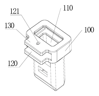
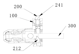
Drawings reproduced from the public patent document for reference.
Frequently asked questions
How does the seat lock without tools?
The seat cushion has a U-shaped bracket. When you press the cushion down, the bracket pushes against wedge-shaped bosses on a sliding part inside the buckle. This compresses an elastic frame. Once the bracket passes the wedges, the frame springs back, trapping the bracket securely.
Can I remove the seat easily?
Yes. The buckle has an exposed unlocking tab. Pushing this tab forces the elastic frame to deform again, retracting the sliding part and freeing the bracket. You can then lift the cushion out by hand.
Is the mechanism durable?
The design relies on elastic deformation rather than complex gears or chains. However, durability depends on the material chosen. In most designs, engineering plastics like PA6-GF30 are used to withstand repeated flexing and cabin temperatures.
Does it rattle?
The patent describes a positioning column and hole system to align the lock cylinder within the buckle body. Proper fit here minimizes play. Tight manufacturing tolerances are required to prevent rattling at the joints during vehicle vibration.
What materials are used?
The patent does not specify exact materials. For production, we typically recommend heat-resistant injection molded plastics such as ABS or PC blends that meet automotive flammability and temperature standards.
Can this design be made and sold in the US?
The patent was filed in China and has lapsed, and the public record shows no US counterpart, so it does not restrict the design in the US or in China. Automotive latching systems may be covered by other US patents - see Patent & Production - so we recommend a freedom-to-operate check before volume production.
Are you affiliated with the patent owner?
No. IP2M is an independent design and manufacturing service working from the public patent document.
Request a quote
Click Request a Quote below to see our email address - copy it, or open your email app with a ready-made message. Please mention patent CN107487232B in the subject.
Helpful details to include:
- Your company and channel (auto supplier, aftermarket brand, fleet operator)
- CAD files of your seat bracket and floor interface
- Target load and locking force requirements
- Material preference (e.g., heat resistance, color)
- Estimated quantity and target price
- Timeline - when you would like samples and the first shipment
You can also reach us at (332) 203-9997.
Page editor: Daniel Chen, Product Research Editor · IP2M
Last updated November 5, 2026. If something on this page looks wrong, email [email protected] and we will check it against the patent.
Interested in building this?
Tell us your target market, quantity and timeline. We reply with options for prototyping, small-batch runs or volume production.
Send your inquiry to
Please put CN107487232B in the subject line and tell us your company, country, estimated quantity and timeline.
Prefer to talk? Call (332) 203-9997.
More product-ready patents
All Car Accessories patents →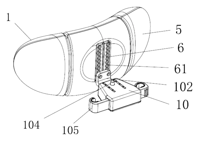
Car Accessories
Car Headrest Pillow with Ratchet Side Wings and Push-Button Reach
Post-mounted car headrest pillow with ratchet side wings and a push-button forward adjustment.
Patent CN212195197U
Car Accessories
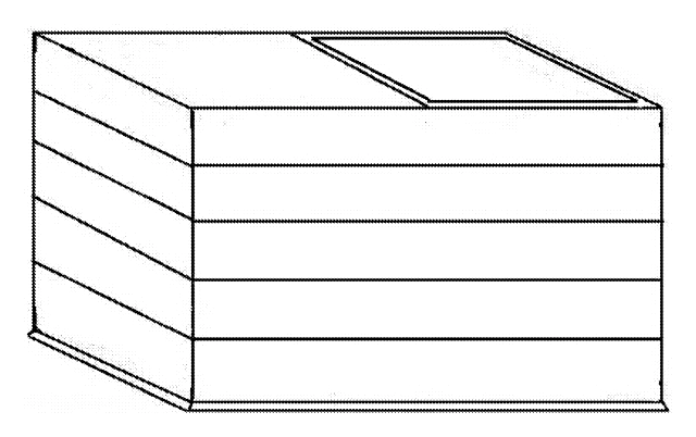
Hard-Shell Rooftop Tent That Doubles as a Cargo Box
Roof box whose hard frames lift on gas struts into a tent with door and skylight, and fold back for luggage.
Patent CN206327275U
Car Accessories
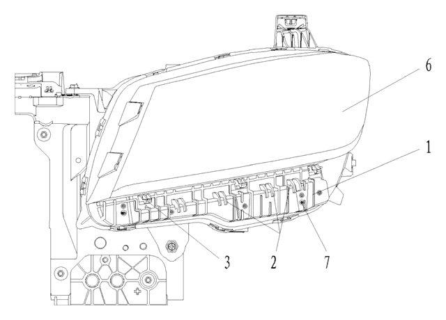
Headlamp-to-Bumper Adapter Bracket That Sets Gap and Flush in Three Directions
Molded bracket under the headlamp: support blocks and snap teeth locate the bumper flange for an even gap.
Patent CN216580316U
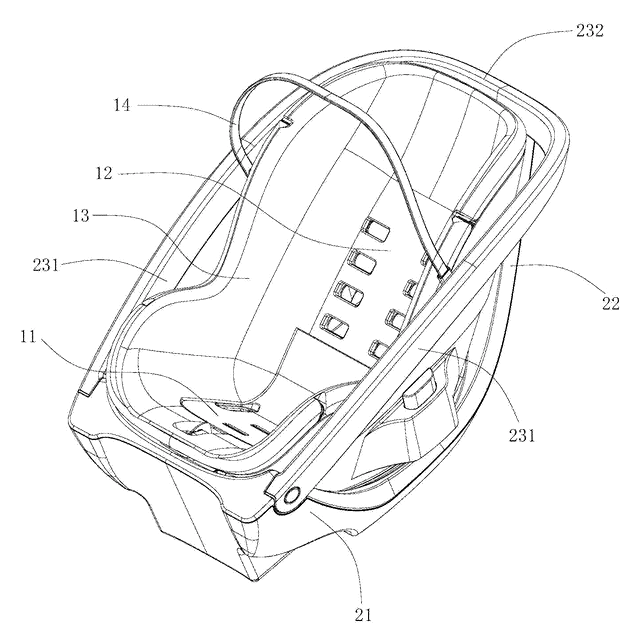
Car Accessories
Infant Car Seat with a Load-Bearing Base That Wraps the Carrier
Infant car seat whose base has a backrest and swing-up side rails, so the carrier can be lighter.
Patent CN206383856U
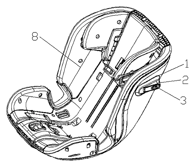
Car Accessories
Retractable Side Impact Protection Block for Child Car Seats
Retractable side-impact block for child seats: springs out to provide side-impact buffering, folds flat.
Patent CN207028930U
Car Accessories
Rain-Deflecting Side Mirror with a Pivoting Air-Guide Plate
Side mirror with a top air duct and folding guide plate that directs airflow across the glass.
Patent CN207345672U
Browse by category
- Apparel & Accessories (41)
- Baby & Kids (27)
- Bags & Luggage (15)
- Bath & Personal Care (28)
- Car Accessories (23)
- Furniture, Bedding & Storage (21)
- Garden & Outdoor (29)
- Health & Wellness (13)
- Home, Kitchen & Cleaning (44)
- Lighting (22)
- Packaging & Containers (11)
- Pet Products (10)
- Phone & Camera Accessories (8)
- Retail Display (23)
- School, Office & Art (32)
- Sports & Recreation (41)
- Tools & Workshop (50)
- Toys & Games (21)
This page is based on the public patent document CN107487232B, assigned to Borgward Automotive China Co Ltd. IP2M is an independent manufacturing service and is not affiliated with, endorsed by or licensed by the patent owner. Images marked as concept renderings are illustrations, not photos of an existing product. Patent status information is provided for reference only and is not legal advice; confirm freedom to operate for your market before production. Full disclaimer.