At a glance
| Patent number | CN107672339B (application CN201711123872) |
| Type | China invention patent (发明专利) - protects product shape, structure and method |
| Original title | A file storage folder (一种档案收纳夹) |
| Patent owner | Jiaxing Erhui Human Resources Co.,Ltd. |
| Inventors | Wang Liwei |
| Filing date | 2017-11-14 |
| Grant date | 2019-07-23 |
| Status (China) | In force in China until at most 2037-11-14 (if annual fees are paid) |
| Patent family | Chinese filings only - no US, European, Japanese, PCT or other filings listed |
| Cited by | 0 later documents |
| Source | Google Patents (search for CN107672339B) |
What the claims cover, in plain language
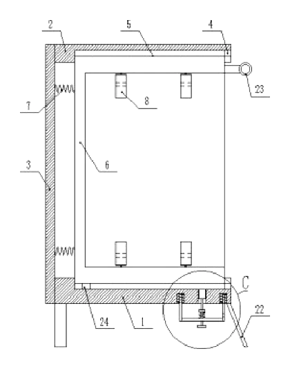
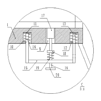
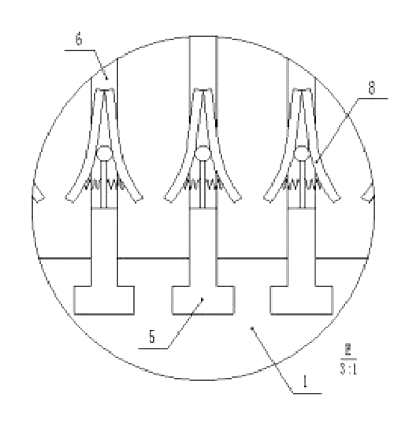
Claim 1 - a file storage clip comprising a bottom plate (1) with a top plate (2) above it, their edges joined by a rear baffle (3). Both plates have symmetrical, evenly arranged T-shaped grooves (4). T-shaped blocks (5) slide in the grooves, with upper and lower blocks joined by a connecting rod (6). A retracting spring (7) connects the rear baffle to the rod. A clip (8) is fixed between the T-shaped blocks. The bottom plate has through holes A (9) aligned with the grooves, flanked by blind holes (10) containing sliding blocks (11). A blocking ring (12) sits at the blind hole edge. A vertical rod A (13) extends down from the sliding block, with a spring A (14) between the block and the ring. A connecting plate (15) links the vertical rods A. Vertical rods B (16) pass through the connecting plate, each topped with a clamping block (17) that slides in through hole A. The T-shaped block has a through hole B (24) matching the clamping block. A disc A (18) on the vertical rod B sits above a spring B (19) resting on the connecting plate, with a disc B (20) at the rod’s bottom. The connecting plates are joined by a fixing rod (21) with a pull ring (23) bearing a mark card.
Claim 2 - the bottom plate has a leg (22) fixed to its lower end, and the T-shaped block edge has a pull ring (23). Claim 3 - the bottom plate and top plate are made of plastic materials. Claim 4 - the distance between the upper and lower ends of the T-shaped block is 35 cm.
This is a simplified reading for orientation only. The legal scope is defined by the exact claim wording in the official Chinese document.
What this means for US production
This patent was filed only in China and is currently in force in China until at most 2037-11-14 (if annual fees are paid). It has no US or other foreign counterpart. Because it is in force, making or selling this exact design in China needs the owner’s permission.
Two points to settle early:
- Other patents may exist. While no foreign patents cite this document, the broader field of mechanical filing devices and spring-loaded document holders contains prior art from various office supply manufacturers. A freedom-to-operate (FTO) review covering the T-slot slider and simultaneous retract mechanism is recommended before committing to tooling for the US market.
- Plastic material selection. The patent specifies plastic plates but does not name the resin. The chosen plastic must withstand repeated spring tension and friction from the sliding blocks without cracking, which affects mold design and material cost.
Customization and manufacturing
What can be customized
| Area | Options |
|---|---|
| Plate dimensions | Overall width, depth and thickness to fit letter, A4 or legal paper sizes |
| Number of slots | Quantity of T-shaped grooves and corresponding linkage components |
| Block spacing | Vertical distance between upper and lower T-shaped blocks (about 35 cm in the patent, adjustable in design) |
| Plastic resin | ABS, PP or other engineering plastics depending on stiffness and cost targets |
| Spring force | Wire gauge and coil count for retracting springs and linkage springs to match document weight |
| Clip style | Binder clip mount, bulldog clip or integrated plastic clamp |
| Color | Molded-in color or painted finish for the plates and blocks |
| Labeling | Mark cards on the pull rings, printed index tabs or adhesive label areas |
Things to plan for (US market)
- CPSC general consumer product rules - if marketed for school use involving children under 12, tracking labels and third-party testing may apply.
- California Proposition 65 - plastic resins, metal springs and any surface coatings must be screened for listed chemicals.
- ASTM D6198 / packaging standards - if sold as part of a larger office kit, outer packaging must meet transit requirements.
How a project runs
- Inquiry - target paper size, number of slots, material preferences and estimated volume.
- Design - CAD modeling of the plates, T-grooves, linkage geometry and spring rates; confirmation of the 35 cm spacing or adjusted dimension.
- Prototype - 3D-printed or CNC-machined samples to test sliding friction, spring return and the one-pull retract action.
- Pilot run - injection molds for the plates and blocks, stamping for metal rods and discs, assembly of a pilot batch for cycle testing.
- Production - full-scale molding, metal component fabrication, sub-assembly of the linkage, final assembly and quality inspection.
Quantities & timeline
The bottom and top plates require multi-cavity injection molds due to their size and the precision needed for the T-shaped grooves. The internal linkage involves stamped metal rods, discs, blocking rings and custom-wound springs. Assembly is labor-intensive because each slot has its own set of sliding blocks, springs and clamping parts. Certification tests for plastics and chemical screening run in parallel with pilot production. Send us your target paper size, number of slots, material preferences, quantity and target price and we will reply with options.
Patent drawings
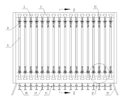
Drawings reproduced from the public patent document for reference.