
Patent CN108081180B
Updated October 25, 2026Torque Wrench Positioning Device with Lockable Setting Tube
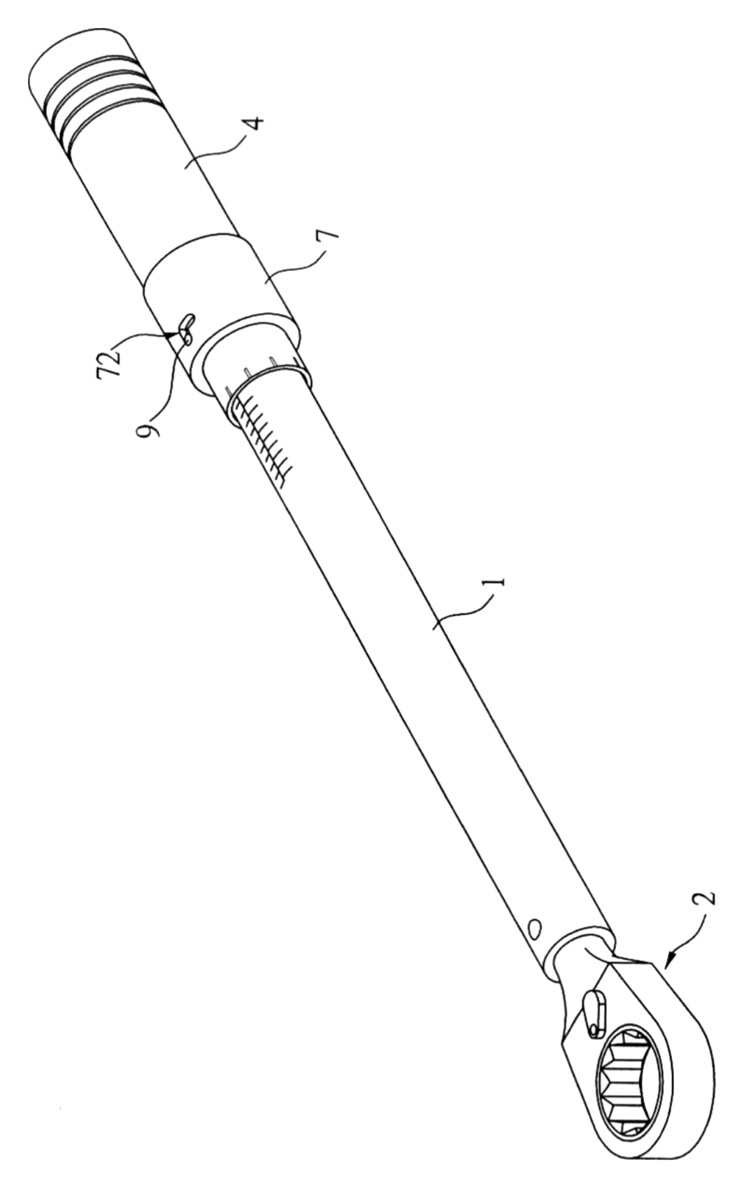
Preset torque wrenches lose accuracy when the setting sleeve is bumped or vibrates loose mid-job. This positioning device solves that problem with a two-stage mechanical lock. After the user presses the outer regulating tube and rotates the control plate to compress the internal spring to the desired torque value, releasing the tube allows an internal spring to push it back into place. As it returns, an angled pushing block forces a positioning bead deep into one of several axial recesses on the inner spine pipe, physically preventing rotation. A bolt riding in an L-shaped slot then shifts from a straight channel into a cross-drilled channel, blocking any further axial movement of the tube. The result is a torque setting that stays exactly where you put it until you deliberately unlock it.
- China invention patent - in force
- No filings outside China
- Hand tools & workshop equipment
- Tubes, springs, positioning bead and bolt assembly
Splat! What let you down?
🔒
Bead-and-recess lock
A positioning bead snaps into one of several long recesses on the spine pipe, physically stopping rotation once set.
📐
L-shaped slot safety
A bolt rides in an L-hole; shifting it into the cross-drilled section blocks the regulating tube from sliding accidentally.
⚙️
Angled pusher block
An internal pushing block with an angled face cams the bead out of the recess when adjusting, and forces it back in when locking.
🛠️
One-hand release
Pressing the regulating tube axially disengages the lock so the user can rotate the setting ring without extra tools.
Bring this product to market
- ✓ Patent vetted China-only family and legal status checked
- 2 Product brief · now How it works, uses and options written up
- 3 Prototype First samples for buyers to review
- 4 Pilot run Small first batch for launch customers
- 5 Volume production Repeat orders at scale
Buyer interest
– of 100 buyers needed to start prototyping
One click, no sign-up. Each vote is one real visitor, and products with the most interest go to prototyping first.
Build team: no members yet. Need a partner, co-funding or skills to build this? Join and we introduce the team once it forms.
The problem
Click-type and preset torque wrenches rely on an internal spring compressed to a specific length. If the outer adjustment sleeve shifts even slightly during use—due to vibration, handling, or bumping against a workpiece—the spring compression changes, and the wrench clicks at the wrong torque. Over-tightening strips threads or cracks components; under-tightening leaves joints loose. According to the patent, the goal is to provide a positioning device that prevents the regulating tube from being touched or moved by accident during operation, ensuring the set torque value remains exact.
The solution
The device adds a mechanical lock between the rotating control plate and the spine pipe, actuated by the regulating tube.
- The spine pipe (3) sits inside the main tube (1) and features several positioning long recesses (31) running along its length.
- A rotating control plate (4) sleeves over the spine pipe. Its stopper section (41) holds a positioning bead (5) inside an embedding hole (411).
- The regulating tube (7) fits over the stopper section. Inside, a pushing block (71) has an angled support face (711). A spring part (8) sits between the pushing block and a support step (44) on the control plate.
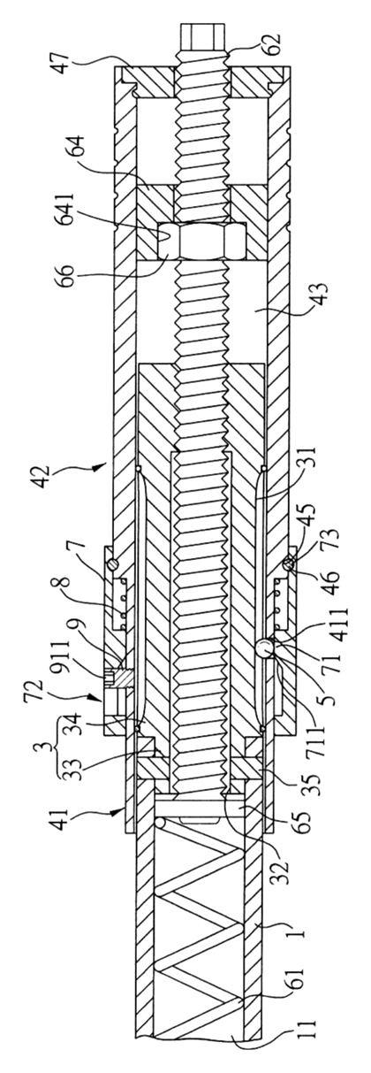
- To adjust, the user presses the regulating tube axially. The angled face cams the positioning bead out of the recess, freeing the control plate to rotate and compress the torsion bullet control component (6).
- Releasing the tube lets the spring push it back. The bead snaps into a new recess, locking the rotation.
- A bolt (9) rides in an L-shaped hole (72) on the tube. Sliding the bolt from the straight hole section (721) into the cross-drilled hole section (722) blocks the tube from moving axially, adding a second layer of security.
Who it is for
- Professional hand tool brands looking to upgrade their preset torque wrench lines with a verifiable anti-drift feature for automotive and aerospace catalogs.
- Industrial maintenance suppliers whose clients need reliable fastening in high-vibration environments like engine bays or heavy machinery.
- OEM tool kit assemblers packaging torque wrenches with bicycles, motorcycles, or electronics where precise, repeatable fastening is critical and users lack calibration equipment.
- Private-label Amazon sellers in the automotive tool niche seeking a distinct mechanical advantage to highlight in product listings against generic click-wrenches.
How it works
The main parts
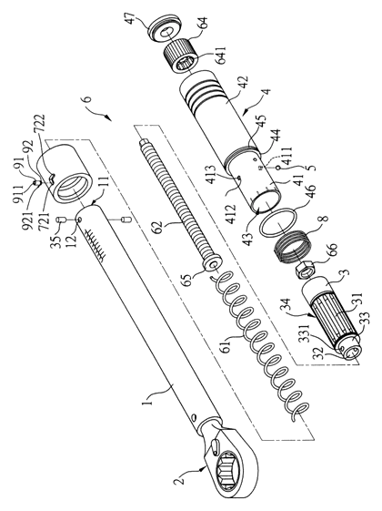
| No. | Part | What it does |
|---|---|---|
| 1 | Main tube | Outer housing; contains the accommodating hole (11) and pin holes (12). |
| 2 | Drive end | Drive spanner for turning fasteners. |
| 3 | Spine pipe | Inner shaft with positioning long recesses (31) and perforation (32). |
| 35 | Pins | Secure the spine pipe inside the main tube via jacks (331). |
| 4 | Rotating control plate | Sleeves over the spine pipe; includes stopper section (41), holding section (42), and combined hole (43). |
| 5 | Positioning bead | Sits in the embedding hole (411); engages the recesses to lock rotation. |
| 6 | Torsion bullet control component | Spring (61), screw rod (62), regulation piece (64), and follow block (65); sets the actual torque threshold. |
| 7 | Regulating tube | Outer sliding sleeve; carries the pushing block (71) and L-shaped hole (72). |
| 8 | Spring part | Returns the regulating tube after adjustment. |
| 9 | Bolt | Screws into the stopper section; rides in the L-hole to lock or release the tube. |
Setting and locking the torque
- Unlock the bolt - turn or slide the bolt (9) so it sits in the straight hole section (721) of the L-hole (72). This frees the regulating tube (7) to move axially.
- Press the tube - push the regulating tube axially. The pushing block’s (71) angled support face (711) forces the positioning bead (5) out of the current positioning long recess (31), compressing the spring part (8).
- Rotate to set - while holding the tube, turn the holding section (42) of the rotating control plate (4). This drives the screw rod (62) through the regulation piece (64), compressing the spring (61) against the follow block (65) to the desired torque value.
- Release to lock - let go of the regulating tube. The spring part (8) pushes it back. The angled face guides the positioning bead into a positioning long recess, physically stopping the control plate from rotating.
- Secure the bolt - shift the bolt into the cross-drilled hole section (722). The tube can no longer slide, preventing accidental unlocking during use.
Applications
Automotive cylinder head assembly
Mechanics tightening cylinder head bolts must follow a strict sequence and torque spec. A bumped adjustment sleeve on a standard wrench can drop the setting by several Newton-meters, risking gasket failure. The bead-and-recess lock ensures the value holds through dozens of repetitive clicks across the engine block.
Bicycle maintenance and assembly
Carbon fiber frames and components have very low torque limits, often between 4 and 6 Nm. A slight accidental twist of the setting ring on a generic wrench can easily double the output, cracking carbon steerer tubes or seat posts. The positive lock gives bike mechanics confidence that the delicate setting remains fixed while working through multiple small bolts.
Aerospace structural fastening
Aircraft assembly requires documented, repeatable torque values where drift is unacceptable. The dual-lock mechanism—bead engagement plus the L-slot bolt—provides a physical verification point. Inspectors can confirm the bolt is seated in the cross-drilled section before the operator begins a shift.
Heavy equipment field repair
Mining and construction machinery operates in high-vibration environments. Technicians using preset wrenches in the field often find settings walking loose due to constant shaking. The spring-loaded bead snapping into a machined recess resists vibration far better than friction-fit adjustment rings.
Electronics manufacturing lines
Assembly workers on production lines tighten screws on chassis or heat sinks hundreds of times per shift. Speed is essential, but stripping a thread on a server rack means scrapping the panel. The press-and-turn adjustment lets workers reset quickly if specs change, while the lock prevents drift during the run.
Where it is less suitable
- Digital electronic torque wrenches - these use strain gauges and microprocessors rather than mechanical spring compression, so this physical locking mechanism does not apply.
- Very high-torque industrial applications - wrenches rated above 1,000 Nm typically use hydraulic or geared multipliers; the internal geometry described here suits standard hand-held ranges.
- Disposable or ultra-low-cost consumer kits - the machining required for the spine pipe recesses, L-holes, and angled pusher block adds manufacturing steps that budget brands may avoid.
Frequently asked questions
How does the positioning bead actually lock the torque setting?
The inner spine pipe has several long grooves machined along its length. When you release the outer regulating tube, an internal spring pushes an angled block against a positioning bead, forcing that bead into one of the grooves. Because the bead is trapped in the groove, the rotating control plate cannot turn, which keeps the internal spring compressed at the exact length you set.
What is the purpose of the L-shaped hole and bolt?
It acts as a secondary safety lock. The bolt rides in a slot shaped like an “L”. When the bolt is in the straight hole section of the L, you can push the tube down to adjust the wrench. Once set, the bolt sits in the cross-drilled hole section. In that position, the tube physically cannot be pushed down, so the bead cannot be accidentally cammed out of its groove if the tool is dropped or bumped.
Do I need a separate tool to change the torque setting?
No. According to the patent description, the user presses the regulating tube down with one hand to disengage the bead, then rotates the holding section to adjust the spring compression. The bolt in the L-hole is positioned in either the straight hole section or the cross-drilled hole section.
Will the positioning bead wear out the grooves over time?
Wear depends on the materials chosen during manufacturing. The patent describes the mechanical interaction but does not specify hardness ratings. For production, the spine pipe would typically be hardened alloy steel, and the bead could be hardened steel or ceramic to withstand thousands of adjustment cycles without deforming the recesses. Cycle testing during prototyping confirms longevity.
How accurate is this mechanism compared to a standard click wrench?
The patent focuses on the locking mechanism rather than the calibration accuracy. The underlying torque measurement still relies on the torsion bullet control component—a spring compressed by a screw rod. The locking device simply ensures that once calibrated, the spring length does not change. The patent does not provide accuracy data or compare it to standard click wrenches.
Can this design be scaled for large 3/4-inch or 1-inch drive wrenches?
The mechanical principle scales, but the components must be sized appropriately. Larger drive wrenches require stiffer springs and higher clamping forces. The spine pipe diameter, bead size, and pushing block angle would all need to be recalculated in the design phase to handle the increased loads without slipping.
Can this design be made and sold in the US?
The patent was filed only in China and is currently in force there, so it does not restrict the design in the US. Torque wrench mechanisms may be covered by other US patents - see Patent & Production - so we recommend a freedom-to-operate check before volume production.
Are you affiliated with the patent owner?
No. IP2M is an independent design and manufacturing service working from the public patent document.
Request a quote
Click Request a Quote below to see our email address - copy it, or open your email app with a ready-made message. Please mention patent CN108081180B in the subject.
Helpful details to include:
- Your company and channel (hand tool brand, industrial supplier, private label seller)
- Drive size and target torque range (Nm or ft-lb)
- Material preferences for the spine pipe, bead, and housing
- Handle grip style and finish requirements
- Estimated quantity and target price
- Timeline - when you would like samples and the first shipment
You can also reach us at (332) 203-9997.
Explore this product
Interested in building this?
Tell us your target market, quantity and timeline. We reply with options for prototyping, small-batch runs or volume production.
Send your inquiry to
Please put CN108081180B in the subject line and tell us your company, country, estimated quantity and timeline.
Prefer to talk? Call (332) 203-9997.
More product-ready patents
All Tools & Workshop patents →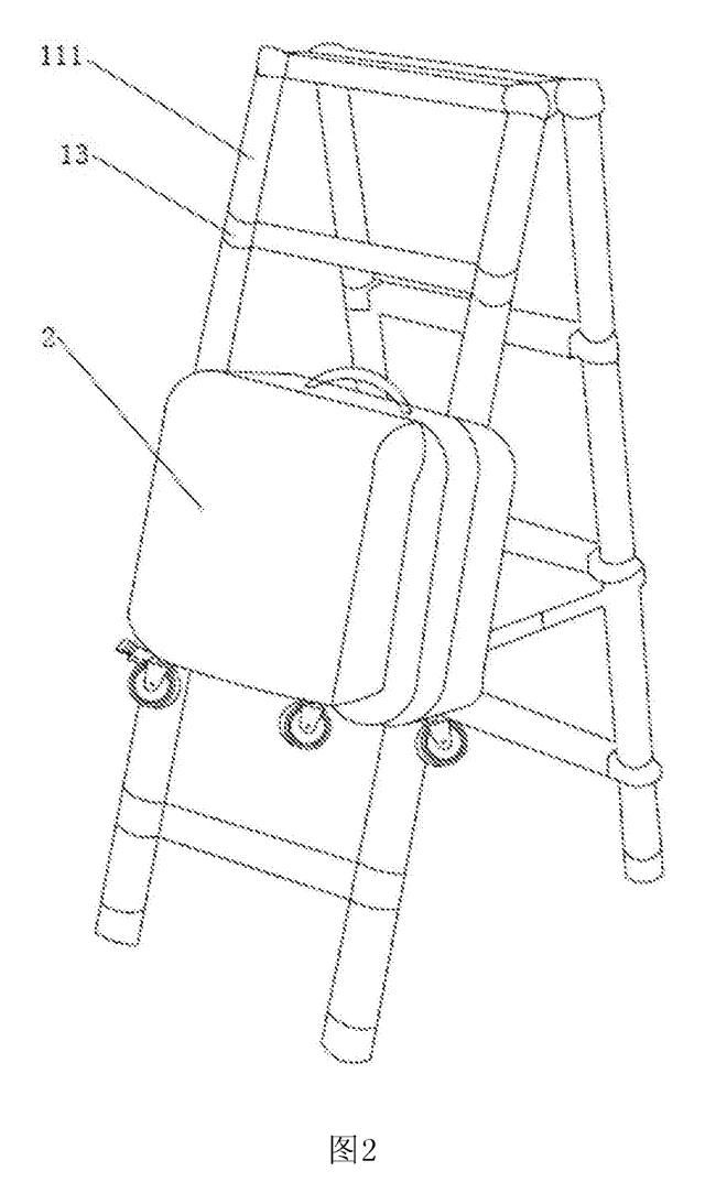
Tools & Workshop
Rolling Tool Box with Telescoping Step Ladder
Telescoping A-frame ladder with an attached rolling tool box that slides to your working height.
Patent CN206290197U
Tools & Workshop
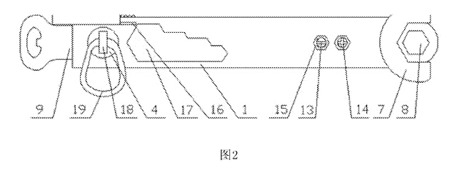
Folding 3-Handle Wrench Multi-Tool
Folding three-handle wrench multi-tool with magnetic screwdriver bits, saw, file and bottle opener.
Patent CN205290875U
Tools & Workshop
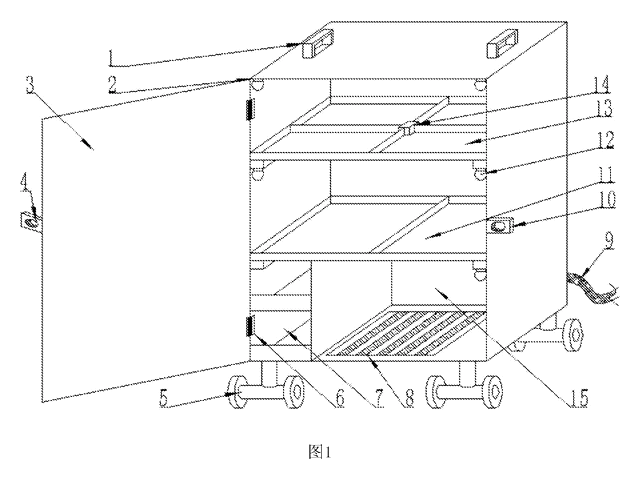
Rolling Auto-Repair Tool Cabinet with Built-In Lights
Lockable rolling tool cabinet for car repair with interior lights, a lubricant tray, parts drawers and a tool bay.
Patent CN205989314U
Tools & Workshop
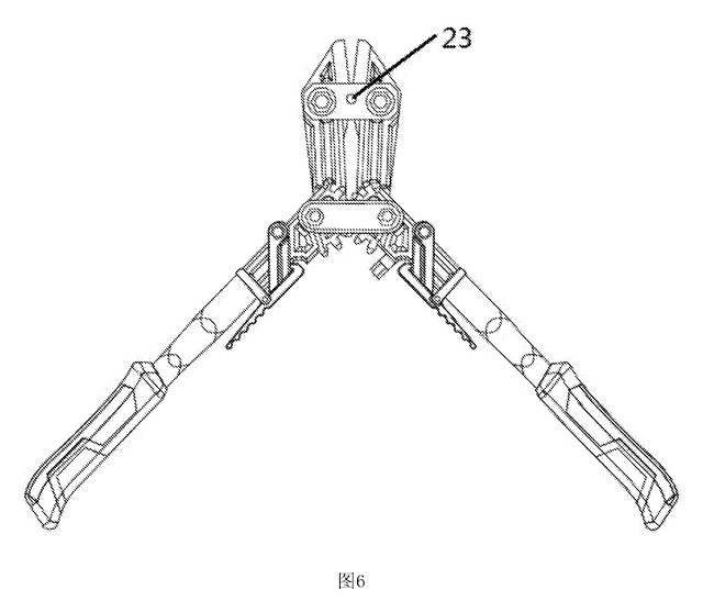
Wide-Opening Folding Bolt Cutter
Bolt cutter with linked, gear-meshing handles that open up to 190° and fold in half for storage.
Patent CN207206226U
Tools & Workshop
Nail-Holding Hammer with Fold-Out Drivers
Hammer with a nail-holding T-slot in the head and fold-out drivers stored in the handle.
Patent CN205254927U
Tools & Workshop
Modular Wrench with Screw-On Heads
Wrench handle with a three-way threaded hub for screw-on adjustable and hex heads, plus a pipe sleeve.
Patent CN206216564U
Browse by category
- Apparel & Accessories (22)
- Baby & Kids (16)
- Bags & Luggage (9)
- Bath & Personal Care (16)
- Car Accessories (10)
- Furniture, Bedding & Storage (12)
- Garden & Outdoor (18)
- Health & Wellness (8)
- Home, Kitchen & Cleaning (24)
- Lighting (12)
- Packaging & Containers (6)
- Pet Products (6)
- Phone & Camera Accessories (4)
- Retail Display (13)
- School, Office & Art (19)
- Sports & Recreation (25)
- Tools & Workshop (27)
- Toys & Games (12)
This page is based on the public patent document CN108081180B, assigned to Individual. IP2M is an independent manufacturing service and is not affiliated with, endorsed by or licensed by the patent owner. Images marked as concept renderings are illustrations, not photos of an existing product. Patent status information is provided for reference only and is not legal advice; confirm freedom to operate for your market before production. Full disclaimer.