At a glance
| Patent number | CN108081180B (application CN201611033094) |
| Type | China invention patent (发明专利) - protects product shape, structure and method |
| Original title | Positioning device of torque spanner (扭力扳手的定位装置) |
| Patent owner | Individual |
| Inventors | Chen Yifu |
| Filing date | 2016-11-22 |
| Grant date | 2019-07-23 |
| Status (China) | In force in China until at most 2036-11-22 (if annual fees are paid) |
| Patent family | Chinese filings only - no US, European, PCT or other filings listed |
| Cited by | 3 later documents |
| Source | Google Patents (search for CN108081180B) |
What the claims cover, in plain language
Claim 1 - a positioning device for a torque wrench comprising a main tube with an accommodating hole, a spine pipe inserted into the main tube having several axial positioning long recesses and a perforation connecting to the accommodating hole. A rotating control plate sleeves over the spine pipe and includes a stopper section, a holding section, and a combined hole. The stopper section has an embedding hole containing a positioning bead. A torsion bullet control component passes through the perforation and combined hole; rotating the control plate adjusts this component to set the torque. A regulating tube sits on the stopper section and contains an internal pushing block with an angled support face. A spring part is placed between the pushing block and a support step. When the regulating tube moves axially, the pushing block forces the positioning bead out of the recess to allow adjustment; when released, the spring returns the tube and the bead re-engages a recess. A bolt rides in an L-shaped hole on the regulating tube to limit or release its axial displacement.
Claim 2 - the L-shaped hole includes a straight hole section and a cross-drilled hole section. In the straight section, the tube can move freely; in the cross-drilled section, movement is restricted. Claim 3 - the bolt has a screw head section with a tool slot and a threaded section that screws into a lockhole with internal threads on the stopper section. Claim 4 - the main tube has pin holes aligning with jacks on the spine pipe, secured by pins. Claim 5 onward - the torsion bullet control component details: a spring, a screw rod, a regulation piece with a steering slot, a follow block, and a nut.
This is a simplified reading for orientation only. The legal scope is defined by the exact claim wording in the official Chinese document.
What this means for US production
This patent was filed only in China. It is currently in force in China until at most 2036-11-22 (if annual fees are paid), meaning manufacturing or selling this exact design within China requires the patent owner’s permission. It has no US or other foreign counterpart.
Two points to settle early:
- Freedom to operate (FTO). Because there is no US counterpart, the design itself is not blocked by this specific Chinese patent in the United States. However, an FTO search covering the target market is still necessary before tooling.
- Other patents may exist. Torque wrench adjustment mechanisms, click-type releases, and locking sleeves are heavily patented by major hand tool manufacturers globally. Features like the specific bead-and-groove engagement or L-slot locking pin may overlap with existing US or international patents held by tool brands, so a targeted FTO review of the locking geometry is essential.
Customization and manufacturing
What can be customized
| Area | Options |
|---|---|
| Drive size | 1/4", 3/8", 1/2", 3/4" square drives to match target torque ranges |
| Torque range | Spring rate and screw rod pitch tailored for specific Nm or ft-lb windows |
| Recess count | Number of positioning long recesses on the spine pipe determines adjustment granularity |
| Materials | Alloy steel for the spine pipe and main tube; hardened steel or ceramic for the positioning bead |
| Handle grip | Rubber, TPR, or knurled metal overmold on the holding section |
| Scale markings | Laser-etched or printed torque scales on the regulating tube or control plate |
| Finish | Black oxide, chrome plating, or nickel plating for corrosion resistance |
Things to plan for (US market)
- ASME B107.300 - the American Society of Mechanical Engineers standard for torque tools, covering performance, accuracy, and test methods for hand torque wrenches.
- ISO 6789 - international standard for hand torque tools, frequently specified by US industrial buyers alongside ASME.
- California Prop 65 - plating chemicals and handle elastomers must be screened for restricted substances.
- Calibration certificates - US industrial and automotive buyers typically require NIST-traceable calibration documentation out of the box.
How a project runs
- Inquiry - specify drive size, torque range, materials, and estimated volume.
- Design - engineer the spine pipe recess spacing, spring rates, pushing block angle, and L-hole dimensions for the target range.
- Prototype - CNC machine sample components to verify bead engagement feel, spring return force, and bolt locking action.
- Testing - run cycle tests to ensure the positioning bead does not wear the recesses prematurely, and verify torque accuracy against ASME/ISO standards.
- Production - progressive stamping or machining for tubes, precision broaching or milling for the spine pipe recesses, spring winding, heat treatment, plating, and final assembly.
Quantities & timeline
Manufacturing this device requires precision machining for the spine pipe’s axial recesses and the L-shaped hole in the regulating tube. The positioning bead and angled pushing block demand tight tolerances to ensure smooth camming action without play. Spring winding and heat treatment for the main tube add specialized processing steps. Tooling setup for the broaching or milling fixtures takes significant lead time. Send us your drive size, torque range, material preferences, quantity and target price and we will reply with options.
Patent drawings
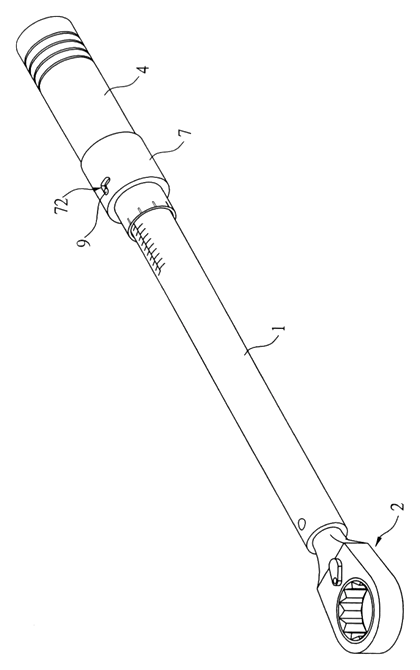
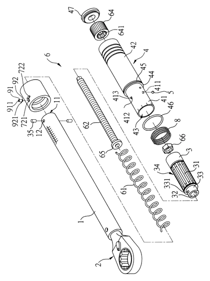
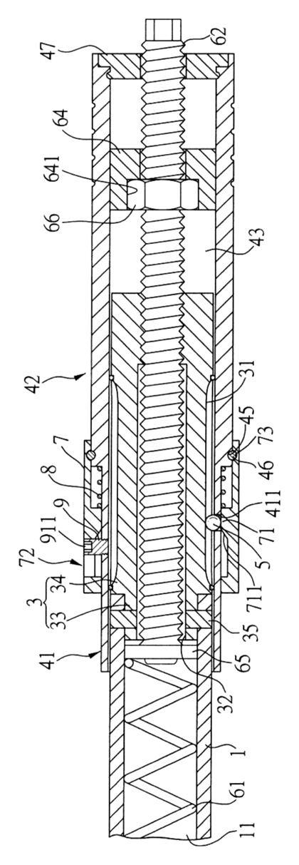
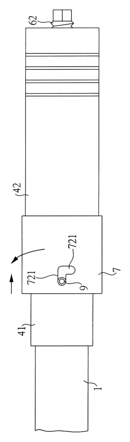
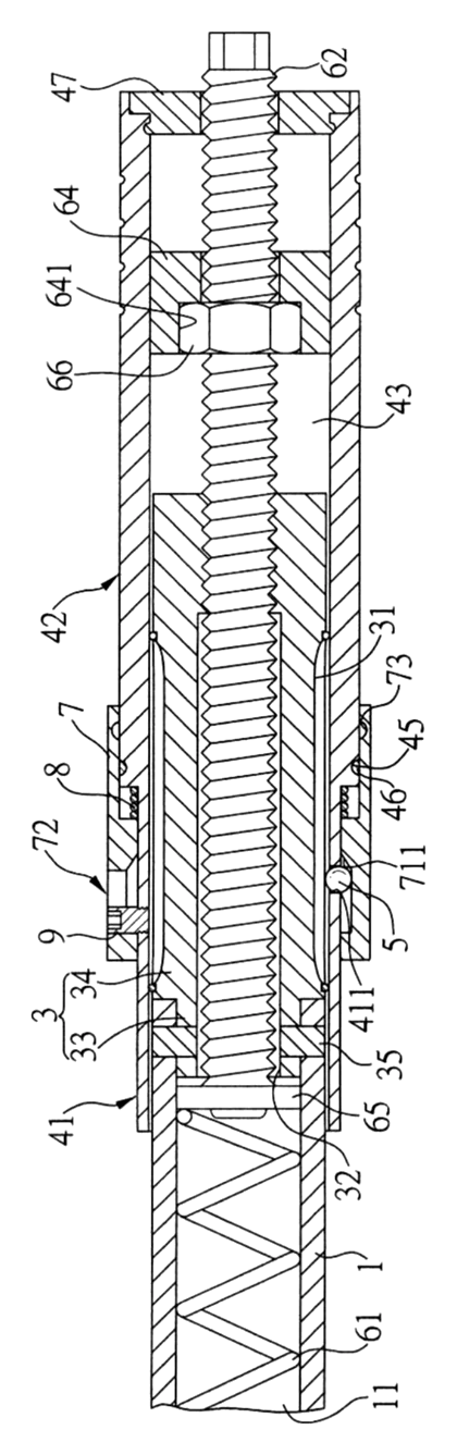
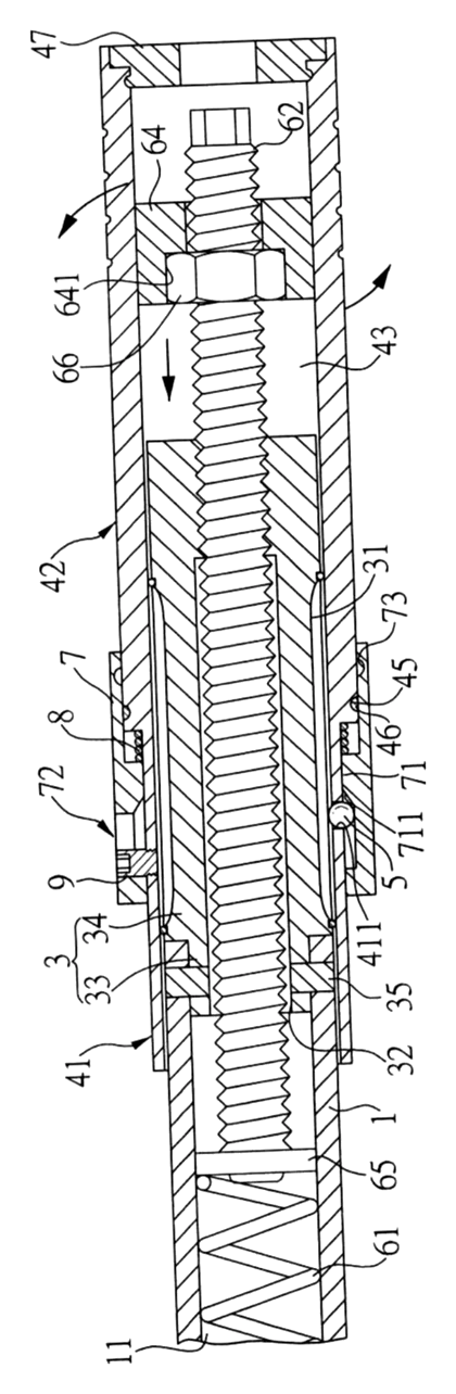
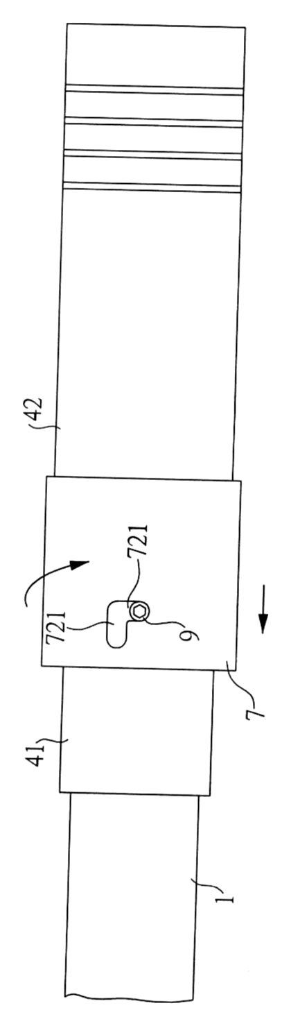
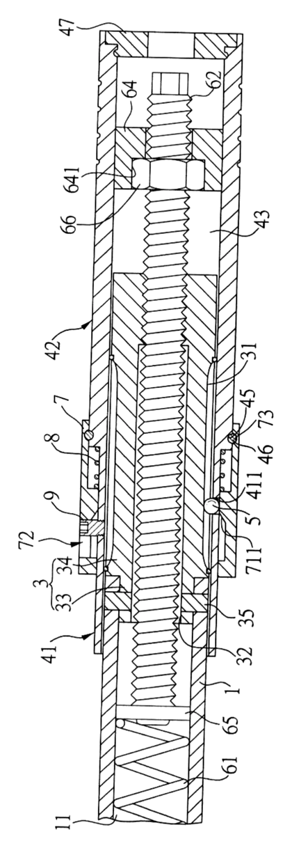
Drawings reproduced from the public patent document for reference.