
Patent CN108278508B
Updated November 5, 2026Three-Sided LED Camping Lantern with Heat Dissipation Channel
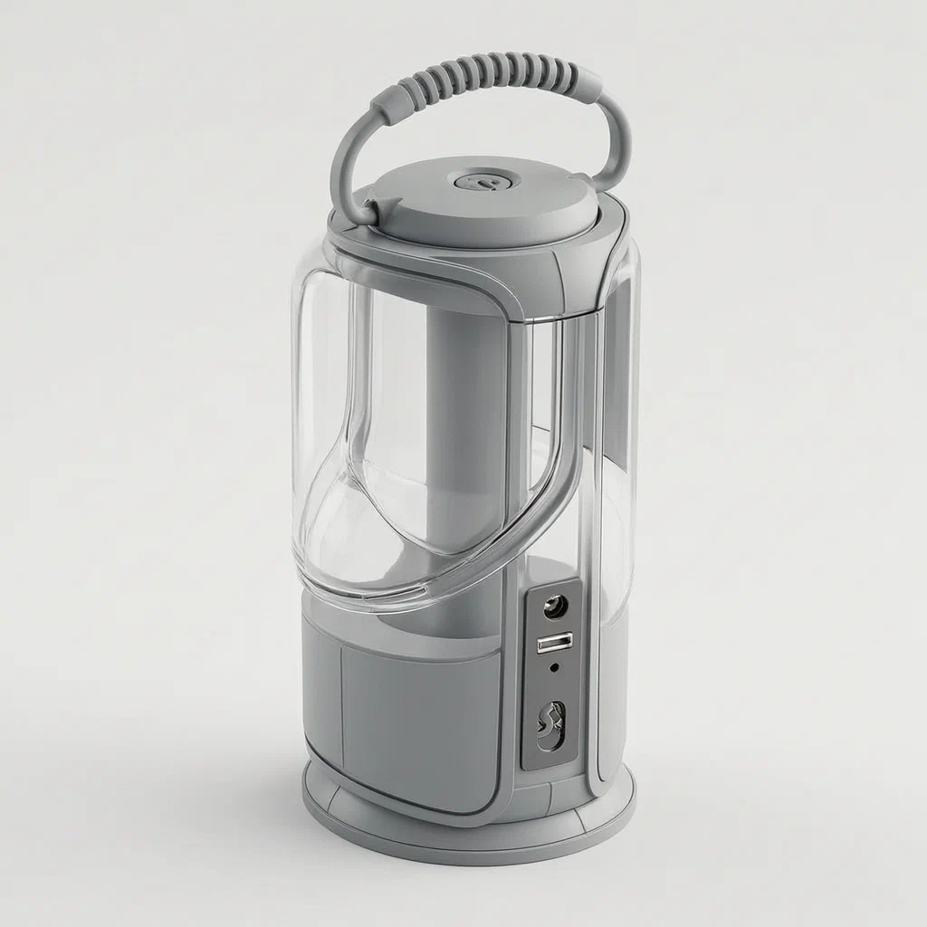
Traditional single-source lanterns often waste light or trap heat. This design solves both by routing air away from the battery and shaping the lens to spread light across three faces. The result is a compact, durable unit suitable for outdoor use where visibility and device charging are critical.
- China invention patent - in force
- No filings outside China
- Outdoor lighting & camping gear
- LED source, plastic diffuser, heat channel
Splat! What let you down?
💡
Three-Sided Illumination
Light exits from three faces via a duckbill-shaped diffuser assembly for wider coverage.
🌡️
Built-in Heat Channel
A gap between the battery and bracket forms a vent path to lower operating temperatures.
🔧
Snap-Fit Assembly
Clamping grooves replace screws, speeding up production and reducing part count.
⚡
USB Charging Port
Integrated interface allows the lantern to charge external devices in field environments.
Bring this product to market
- ✓ Patent review Patent family and legal status reviewed in the relevant jurisdictions.
- 2 Product brief · now How it works, uses and options written up
- 3 Prototype First samples for buyers to review
- 4 Pilot run Small first batch for launch customers
- 5 Volume production Repeat orders at scale
Buyer interest
– of 100 buyers needed to start prototyping
One click, no sign-up. Each vote is one real visitor, and products with the most interest go to prototyping first.
Build team: no members yet. Need a partner, co-funding or skills to build this? Join and we introduce the team once it forms.
Patent Rights & Team Participation
Before joining a development team, participants should ensure they have the necessary rights or authorization to participate in the project.
Participation is generally appropriate where:
- You own the relevant patent rights or have obtained permission or a license from the rights holder.
- The relevant patent rights have expired or have been legally invalidated in the jurisdictions where the planned activities will take place.
- The planned development, manufacturing, and commercialization activities have been independently assessed and do not infringe applicable patent rights in the relevant jurisdictions.
Important: Being located outside a country where a patent is protected does not automatically exempt you from patent infringement risks. Patent rights may apply based on where development, manufacturing, use, sale, or import activities take place.
IP2M does not grant any patent license or authorization through team participation. Joining a project does not provide permission to use, manufacture, or commercialize patented technology.
The problem
Many portable camping lights suffer from two main issues: uneven light distribution and thermal management. Single-point LEDs often create hot spots or require bulky reflectors to spread light, leading to energy loss. Additionally, sealed housings can trap heat generated by the battery and LED driver, potentially shortening component life or causing safety concerns during extended use. Traditional assembly methods relying on multiple screws also increase labor costs and complexity during manufacturing.
The solution
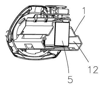
This patent describes a camping lamp that addresses these issues through structural optimization. The core solution involves a bracket (1) that holds the battery portion (5). Crucially, a specific gap is maintained between the battery and the inner wall of the bracket, creating a heat dissipation channel (12). This channel connects to heat dissipation openings (13) at the bottom of the lamp housing (2), allowing passive airflow to carry heat away from the sensitive electronics.
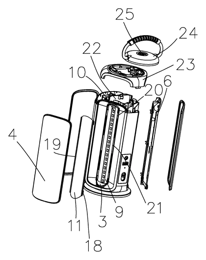
For illumination, the light source portion (3) consists of a circuit board with LED beads. It is enclosed within a diffuser (6) and a first light-transmitting plate (4). These components are arranged vertically and shaped to form a “duckbill” cross-section. A second light-transmitting plate (11) with a larger curvature radius than the first plate sits on the surface of the diffuser. This dual-curve arrangement refracts light to widen the irradiation range across three sides while keeping the profile flat and efficient.
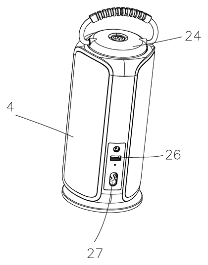
The assembly mechanism replaces screws with a clamping groove (15) formed by positioning blocks on the housing. Matching clamping blocks on the diffuser and plates snap into place, simplifying the build process. A flexible membrane switch (25) on the top cap provides operation control while maintaining better sealing against moisture compared to mechanical buttons.
Who it is for
- Outdoor Gear Brands: Companies looking to differentiate their lantern line with integrated charging capabilities and superior thermal design.
- Amazon Sellers: Sellers who need lightweight, compact packaging solutions; the flat “duckbill” shape reduces shipping volume compared to cylindrical lanterns.
- Emergency Kit Manufacturers: Buyers requiring reliable, multi-function devices that can serve as both primary light sources and power banks for phones or radios.
- OEM/ODM Partners: Manufacturers seeking a pre-engineered structural design that minimizes assembly time through snap-fit mechanisms rather than screw-driven processes.
How it works
The main parts
The device is composed of several interlocking modules designed for durability and ease of service.
| No. | Part | Function |
|---|---|---|
| 1 | Bracket | Structural backbone; houses the battery and creates the heat channel. |
| 2 | Lamp Housing | Outer shell containing windows for light exit and heat vents. |
| 3 | Light Source | Circuit board with LED beads generating the illumination. |
| 4 | First Plate | Inner transparent layer matching the diffuser to form the duckbill shape. |
| 5 | Battery | Power source placed within the bracket’s cavity. |
| 6 | Diffuser | Central scattering cover that spreads light evenly. |
| 11 | Second Plate | Outer curved lens with higher radius for focused refraction. |
| 12 | Heat Channel | Air gap between battery and bracket wall. |
| 15 | Clamping Groove | Snap-fit interface replacing traditional fasteners. |
| 25 | Membrane Switch | Top-mounted control for waterproof operation. |
| 26 | USB Interface | Side port for charging external devices. |
Operating Steps
- Power On: The user presses the flexible membrane switch on the top cap. This completes the circuit to the PCB.
- Light Generation: LED beads on the circuit board emit light inward toward the diffuser.
- Refraction: Light passes through the scattering cover and the first transparent plate. It then hits the second transparent plate, whose greater curvature bends the rays outward.
- Distribution: The “duckbill” geometry ensures light exits uniformly from three vertical faces, minimizing dark spots.
- Cooling: As the LEDs and battery operate, heat rises into the designated gap (channel 12). Convection currents draw this warm air down and out through the openings at the base of the housing.
- Charging Mode: If connected, the USB interface draws power from the battery to charge external devices, managed by the internal driver circuit.
Applications
Base Camp Lighting
The three-sided emission pattern makes this ideal for illuminating tents or shelters without needing to reposition the lamp frequently. The wide beam covers sleeping areas effectively.
Emergency Power Backup
Since the unit includes a USB interface, it serves as a dual-purpose tool. Users can rely on it for light during outages and then use the stored energy to charge smartphones or GPS units.
Night Hiking and Fishing
The compact, flat profile fits easily into backpack pockets. The heat dissipation channel ensures the device remains safe to handle even after hours of continuous use in humid conditions.
Vehicle Repair Kits
Mechanics working under cars at night benefit from the stable, directional light. The snap-fit construction suggests durability against vibration, making it suitable for automotive emergency kits.
Where it is less suitable
- High-Intensity Search Lights: The design prioritizes broad, ambient illumination rather than a focused long-range beam.
- Submersion Environments: While the membrane switch improves sealing, the heat vents at the bottom allow airflow, meaning the unit is not fully waterproof for underwater use.
- Fixed Installation: The portable nature and battery dependency make it less suited for permanent architectural lighting applications.
Patent & Production
At a glance
| Patent number | CN108278508B (application CN201810212538) |
| Type | China invention patent (发明专利) - protects product method and structure |
| Original title | A Three-Sided Luminous Camping Lamp (一种三面发光的野营灯) |
| Patent owner | Guangdong Xiaosong Technology Co., Ltd. |
| Inventors | Liu Qiang |
| Filing date | 2018-03-15 |
| Grant date | 2024-03-29 |
| Status (China) | In force - valid until at most 2038-03-15, subject to payment of annual fees |
| Patent family | Public record shows Chinese filings only - no US, European, Japanese, PCT or other filings listed |
| Cited by | 0 later documents |
| Source | Google Patents (search for CN108278508B) |
What the claims cover, in plain language
Claim 1 defines the core structure: a bracket holding a battery, a lamp housing with windows, and an optical system comprising a light source, a diffuser, and two transparent plates. Key features include the heat dissipation channel formed by a gap between the battery and the bracket wall, venting through openings at the housing bottom. The optical setup uses a “duckbill” shape created by the diffuser and first plate, with a second plate having a larger curvature radius to focus light. Assembly relies on clamping grooves and blocks rather than screws.
Claim 2 specifies the connection details for the second transparent plate, using a third clamping block and positioning block that fit into bayonets and grooves on the diffuser.
Claim 3 adds a vertical switch power strip inside the bracket, topped with a flexible membrane switch housed in a top cap to enhance leakproofness.
Claim 4 introduces side through-holes equipped with USB interfaces and/or charging ports for external device power.
This is a simplified reading for orientation only. The legal scope is defined by the exact claim wording in the official Chinese document.
What this means for US production
This patent was filed in China and is currently in force. Making or selling this specific configuration in China requires the owner’s permission. The public record shows no US or other foreign counterpart.
Two points to settle early:
- Other patents may exist. Outdoor lighting and portable power banks are heavily patented fields. Features like heat channels, duckbill optics, or integrated USB charging may be covered by other US utility patents held by major brands (e.g., Goal Zero, BioLite, Anker) or smaller entities. A freedom-to-operate (FTO) review is strongly recommended before tooling.
- Design-around potential. Since there is no US counterpart, minor structural changes (e.g., altering the heat vent location or changing the lens curvature ratio) might avoid infringement of the Chinese patent if manufacturing occurs elsewhere, but US patent landscape analysis is still required for sales in the United States.
Customization and manufacturing
What can be customized
| Area | Options |
|---|---|
| Housing Material | ABS, PC, or PP plastics; color options include black, orange, green. |
| Lens Clarity | Clear, frosted, or amber-tinted diffusers for different ambiance. |
| Battery Capacity | Standard Li-ion cells or NiMH packs depending on runtime needs. |
| Interface Type | USB-A, USB-C, or proprietary magnetic connectors. |
| Switch Mechanism | Membrane switch (as claimed) or tactile button with rubber seal. |
| Dimensions | Overall height and width adjusted for packaging constraints. |
Things to plan for (US market)
- UL 62368-1 - Audio/video, information and communication technology equipment safety standard, often applied to portable power banks and electronics.
- FCC Part 15 - Electromagnetic interference requirements for digital devices, including LED drivers and charging circuits.
- California Prop 65 - Warning labels required if materials contain listed chemicals (common in some plastics and solder).
- DOT/IATA Regulations - Lithium-ion battery transport rules apply if the unit contains rechargeable cells.
How a project runs
- Inquiry - Define target lumens, battery capacity, and physical size limits.
- Design Review - Verify heat channel dimensions and lens curvature against optical simulation software.
- Prototype - Create 3D-printed housings and test off-the-shelf LED modules.
- Validation - Conduct thermal testing and IP rating checks (splash resistance).
- Tooling - Develop injection molds for the bracket, housing, and diffuser components.
Quantities & timeline
Injection molds for the complex duckbill lenses and snap-fit brackets require high precision. Thermal performance must be validated before mass production to ensure the heat channel functions as intended. Send us your target lumen output, battery specs, material preferences, quantity and target price and we will reply with options.
Production notes
Tooling and process
Injection molding is likely the primary process for the housing, diffuser, and transparent plates. Die-cast aluminum could be used for the bracket if higher thermal conductivity is desired, though plastic is more common for cost. PCB assembly will involve surface-mount technology for the LED drivers.
Cost drivers
Costs typically depend heavily on the mold complexity for the curved lenses and the quality of the LED binning. Battery cell selection and IP sealing materials also contribute significantly to the bill of materials.
Prototyping path
Start with 3D-printed housings to verify fit and form. Off-the-shelf drivers and LEDs are typically used for initial thermal tests. Once the heat channel efficiency is confirmed, move to soft tooling for the lenses.
What we would change before tooling
We would verify the snap-fit tolerance in the prototype phase to prevent assembly failures. Adjustments to the heat vent size may be needed based on real-world thermal imaging results.
Common failure points
Heat buildup is a risk if the channel is blocked or too narrow. Water ingress at the seal around the membrane switch is another potential failure mode. Lens yellowing over time due to UV exposure is typically mitigated with stabilizers.
Patent drawings
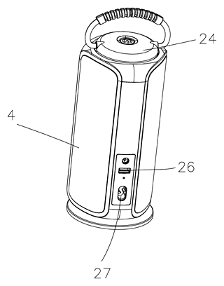
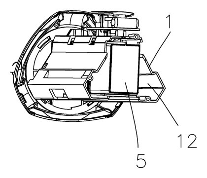
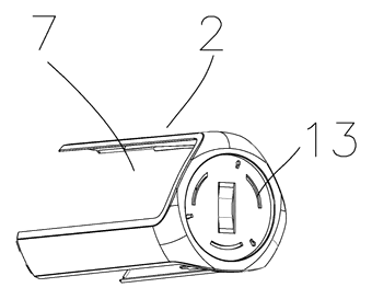
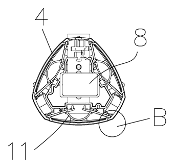
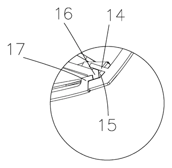
Drawings reproduced from the public patent document for reference.
Frequently asked questions
How does the heat dissipation work?
The design reserves a gap between the battery and the bracket wall, creating a channel. Heat rises from the battery and LEDs into this channel and exits through openings at the bottom of the lamp housing. This passive cooling helps maintain lower operating temperatures.
Why is the lens shape called “duckbill”?
The first transparent plate and the diffuser align to form a cross-section resembling a duck’s bill. This shape, combined with the second curved plate, helps spread the light across three faces efficiently while keeping the lamp body relatively flat.
Is the assembly difficult?
No. The patent emphasizes a snap-fit design using clamping grooves and blocks. This eliminates the need for screws in the main optical assembly, which speeds up manufacturing and reduces part count.
Can it charge my phone?
Yes. Claim 4 mentions USB interfaces on the side of the housing. This allows the lantern to act as a power bank for external devices, provided the battery capacity is sufficient for your needs.
Is it waterproof?
The patent describes a flexible membrane switch to improve leakproofness. However, the presence of heat dissipation openings at the bottom means it is not fully submersible. It is likely splash-resistant but should not be used in heavy rain or submerged water.
Does the light have adjustable brightness?
The patent focuses on the structural distribution of light. Brightness control depends on the driver circuit chosen during production. Dimming features can be added but are not explicitly detailed in the structural claims.
Can this design be made and sold in the US?
The patent is in force in China, and the public record shows no US counterpart. Therefore, this specific patent does not restrict making or selling in the US. However, you must conduct a freedom-to-operate search to ensure no other US patents cover similar heat-dissipation or optical designs in the camping gear sector.
Are you affiliated with the patent owner?
No. IP2M is an independent design and manufacturing service working from the public patent document.
Request a quote
Click Request a Quote below to see our email address - copy it, or open your email app with a ready-made message. Please mention patent CN108278508B in the subject.
Helpful details to include:
- Your company and channel (outdoor brand, Amazon seller, emergency kit supplier)
- Target lumen output and battery capacity (mAh)
- Preferred materials (ABS, PC, etc.) and colors
- Interface requirements (USB-C, USB-A, wireless charging add-on?)
- Estimated quantity and target price
- Timeline - when you would like samples and the first shipment
You can also reach us at (332) 203-9997.
Page editor: Emily Zhang, Product Editor · IP2M
Last updated November 5, 2026. If something on this page looks wrong, email [email protected] and we will check it against the patent.
Interested in building this?
Tell us your target market, quantity and timeline. We reply with options for prototyping, small-batch runs or volume production.
Send your inquiry to
Please put CN108278508B in the subject line and tell us your company, country, estimated quantity and timeline.
Prefer to talk? Call (332) 203-9997.
More product-ready patents
All Lighting patents →
Lighting
Wrist-Worn Flashlight with Click-Lock Angle Adjustment
Rechargeable wrist flashlight whose lamp turns and locks at an angle with a push button.
Patent CN113915544B
Lighting
Self-Folding Desk Lamp That Turns into a Phone Stand
Desk lamp with a shape-memory stem that unfolds when warm and folds into a phone stand.
Patent CN213237087U
Lighting
Ring-Shaped Outdoor Lantern That Lifts Off a Power-Bank Charging Base
Ring lantern with a battery handle that docks in a cone base with its own battery, clamp and charging plug.
Patent CN212408329U
Lighting
LED Flameless Candle with an Outside Flame Shade and Wax Dish Top
Battery LED candle: flame shade stands above a dished wax top, angled LEDs light a printed wick.
Patent CN205424561U
Lighting
Telescoping Tripod Portable Work Light with Fold-In Light Panels
Telescoping tripod work light with dual light panels that fold flat into the base.
Patent CN207298471U
Lighting
Self-Cooling and Self-Cleaning LED Street Light with Rainwater Harvesting
LED street lamp that harvests rain to cool its heat sink and spray-wash the lens automatically.
Patent CN205480639U
Browse by category
- Apparel & Accessories (41)
- Baby & Kids (27)
- Bags & Luggage (15)
- Bath & Personal Care (28)
- Car Accessories (23)
- Furniture, Bedding & Storage (21)
- Garden & Outdoor (29)
- Health & Wellness (13)
- Home, Kitchen & Cleaning (44)
- Lighting (22)
- Packaging & Containers (11)
- Pet Products (10)
- Phone & Camera Accessories (8)
- Retail Display (23)
- School, Office & Art (32)
- Sports & Recreation (41)
- Tools & Workshop (50)
- Toys & Games (21)
This page is based on the public patent document CN108278508B, assigned to Guangdong Xiaosong Technology Co., Ltd.. IP2M is an independent manufacturing service and is not affiliated with, endorsed by or licensed by the patent owner. Images marked as concept renderings are illustrations, not photos of an existing product. Patent status information is provided for reference only and is not legal advice; confirm freedom to operate for your market before production. Full disclaimer.