
Patent CN108887818B
Updated November 8, 2026LED Light-Up Umbrella with Suspended Sealed Bulbs
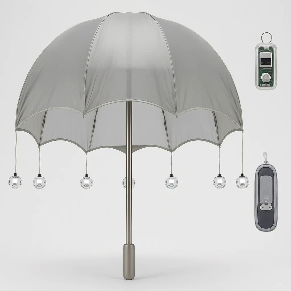
Standard umbrellas have dark canopies that blend into rainy streets, making pedestrians hard for drivers to see. Top-mounted lights often glare directly at the user or fail to illuminate the sides. This design hangs multiple sealed LED units from the rib tips using elastic cords. As the user moves, the lights sway, creating dynamic visibility from all angles. The transparent sealing protects the electronics from rain, while the storage case doubles as a wireless charger, activating only when the umbrella is properly seated.
- China invention patent - lapsed
- No filings outside China
- Outdoor gear & safety accessories
- Sealed LED modules, elastic suspension, wireless charging case
Splat! What let you down?
💡
Suspended LEDs
Light units hang from rib tips on elastic cords, swaying to provide dynamic visibility.
🌧️
Sealed Modules
Each LED unit is fully enclosed in a transparent waterproof structure to prevent leakage.
🔋
Wireless Charging Case
The storage sleeve contains a coil that charges the umbrella automatically upon insertion.
🛡️
Blunt Safety Tip
The handle shaft extends beyond the canopy with a blunt end to trigger the switch safely.
Bring this product to market
- ✓ Patent review Patent family and legal status reviewed in the relevant jurisdictions.
- 2 Product brief · now How it works, uses and options written up
- 3 Prototype First samples for buyers to review
- 4 Pilot run Small first batch for launch customers
- 5 Volume production Repeat orders at scale
Buyer interest
– of 100 buyers needed to start prototyping
One click, no sign-up. Each vote is one real visitor, and products with the most interest go to prototyping first.
Build team: no members yet. Need a partner, co-funding or skills to build this? Join and we introduce the team once it forms.
Patent Rights & Team Participation
Before joining a development team, participants should ensure they have the necessary rights or authorization to participate in the project.
Participation is generally appropriate where:
- You own the relevant patent rights or have obtained permission or a license from the rights holder.
- The relevant patent rights have expired or have been legally invalidated in the jurisdictions where the planned activities will take place.
- The planned development, manufacturing, and commercialization activities have been independently assessed and do not infringe applicable patent rights in the relevant jurisdictions.
Important: Being located outside a country where a patent is protected does not automatically exempt you from patent infringement risks. Patent rights may apply based on where development, manufacturing, use, sale, or import activities take place.
IP2M does not grant any patent license or authorization through team participation. Joining a project does not provide permission to use, manufacture, or commercialize patented technology.
The problem
Pedestrians in low-light conditions are difficult for drivers to spot, especially under heavy rain when visibility drops. Traditional umbrellas rely on ambient street lighting or simple reflective strips that do not emit light. Some designs attempt to add lights to the top of the canopy, but these fixed points cast shadows below the umbrella and can blind the user if angled incorrectly. Furthermore, integrating electronics into an umbrella poses risks: water ingress can short-circuit components, and rigid wiring along the ribs restricts movement or breaks when the umbrella folds. There is also the challenge of recharging; plugging in small devices is inconvenient, and exposed ports compromise water resistance.
The solution
- An umbrella body comprises a canopy, a rib structure (frame), a shaft, and a handle. The rib structure has multiple outer ends.
- Multiple LED light-emitting elements are suspended from these ends via connectors. These connectors include an elastic portion, allowing the lights to swing freely during use.
- Each LED element is a self-contained module: a bracket holds the LED lamp, driving structure, and energy supply (battery). This assembly is covered by a transparent sealing structure which includes light-transmitting parts and a flexible layer with through-holes.
- The canopy features first diversion zones above each rib end. These zones have smaller lower openings facing the ends, helping to channel water away from the hanging lights.
- The rib structure consists of inner and outer frames that clamp the canopy. The outer frame ends support the suspension points.
- A storage member (case) holds the folded umbrella. It contains a wireless charging device with a coil and a voltage-controlled switch.
- The umbrella shaft protrudes past the canopy to form a convex end with a blunt tip. When the umbrella is inserted into the case, this blunt tip presses against the switch, completing the circuit and initiating wireless charging.
Who it is for
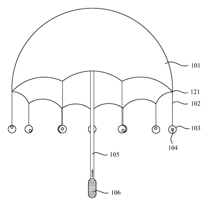
- Safety Gear Brands: Companies producing high-visibility rainwear or pedestrian safety accessories who need a product that actively emits light rather than just reflecting it.
- Night Market & Festival Merchants: Sellers looking for eye-catching items where the swinging lights create a dynamic visual effect for crowds.
- Outdoor Retailers: Stores selling camping or hiking gear that require robust, weatherproof electronic integration in handheld tools.
- Corporate Gift Suppliers: Firms needing distinctive promotional items with functional tech features like automatic charging cases.
How it works
The main parts
| No. | Part | What it does |
|---|---|---|
| 101 | Canopy | Covers the user; includes diversion zones to shed water. |
| 102 | Connectors | Elastic cords suspending the lights; allow swinging motion. |
| 103 | LED Elements | Self-contained light units hanging from rib tips. |
| 104 | LED Lamp | Light source inside the sealed element. |
| 105 | Shaft/Handle | Structural core; shaft extends to a blunt convex end. |
| 121 | Rib Ends | Attachment points for the hanging connectors. |
| N/A | Storage Case | Holds umbrella; contains wireless coil and pressure switch. |
Operating Steps
- Deployment: Open the umbrella. The LED elements hang from the rib tips on elastic connectors.
- Activation: According to the patent, some configurations include switches activated by motion or manual control within the sealed unit.
- Movement: As the user walks, the elastic connectors cause the LED elements to sway. This creates a multi-angle light display, increasing visibility to observers from different directions.
- Protection: Rain hits the canopy and flows off. The transparent sealing structure protects the internal electronics of each hanging bulb from moisture.
- Storage & Charging: Fold the umbrella and insert it into the storage case. The blunt tip of the shaft presses the voltage-controlled switch inside the case. This connects the external power adapter (plugged into the case) to the wireless charging coil, which transmits energy to the battery inside the umbrella without physical contact ports.
Applications
Urban Commuting
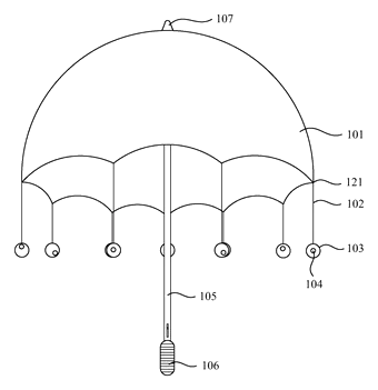
Pedestrians crossing busy intersections at night benefit from the dynamic swinging lights, which catch driver attention more effectively than static reflectors.
Festivals and Night Markets
Vendors and attendees use the umbrella for both rain protection and visual flair. The moving lights attract customers and enhance the festive atmosphere.
Camping and Outdoor Events
Campers use the umbrella as a portable light source around tents. The sealed electronics withstand damp grass and morning dew without failing.
Emergency Preparedness
Included in disaster kits, the umbrella provides immediate illumination and signaling capability during storms or power outages, thanks to its independent battery system.
Where it is less suitable
- High-Wind Storms: The hanging elements may swing excessively in strong gusts, potentially causing noise or tangling.
- Compact Carry Requirements: The bulky storage case required for wireless charging adds significant weight and volume compared to standard compact umbrellas.
- Cold Climates: Battery performance typically drops in freezing temperatures, limiting run-time unless specialized cells are used.
Patent & Production
At a glance
| Patent number | CN108887818B (application CN201810833051) |
| Type | China invention patent - protects method and structure |
| Original title | LED Light-Emitting Umbrella (LED发光伞) |
| Patent owner | Dongguan Wenyu Industrial Co Ltd |
| Inventors | Ye Weibing |
| Filing date | 2018-07-26 |
| Grant date | 2020-10-23 |
| Status (China) | Lapsed - terminated for non-payment of annual fees (recorded 2025-07-25) |
| Patent family | Public record shows Chinese filings only - no US, European, Japanese, PCT or other filings listed |
| Cited by | 0 later documents |
| Source | Google Patents (search for CN108887818B) |
What the claims cover, in plain language
Claim 1 describes an LED umbrella with a body comprising a canopy, stand, shaft, and handle. Key feature: multiple LED light-emitting elements are suspended from the ends of the umbrella stand via connectors. Each element includes a bracket, LED, drive structure, energy supply, and a transparent sealing structure covering them. The sealing structure has light-transmitting parts and a flexible layer with holes. The canopy has diversion zones with openings facing the ends. The stand has inner and outer structures clamping the canopy. The shaft has a blunt convex end. A storage member holds the umbrella and includes a wireless charging device (coil) and a voltage-controlled switch activated by the blunt end pressing it.
Claim 2 specifies the number of LED elements matches the number of rib ends. Claim 3 allows 1 to 20 LEDs per element, with varying counts between elements. Claim 4 allows multiple LEDs per element with different emission directions. Claim 5 details the inner frame structure with intermediate nodes also supporting lights. Claim 6 notes lights on intermediate nodes have lower power/volume than those on ends. Claims 7-9 describe the shape of the elements (spherical or molded figures like towers, cars, insects). Claim 10 details the internal mounting cavity, protective layers, and specific hole shapes (cylindrical/truncated with air bubbles) for the flexible layer.
This is a simplified reading for orientation only. The legal scope is defined by the exact claim wording in the official Chinese document.
What this means for US production
This patent was filed in China and is now lapsed, so it no longer restricts anyone in China either. The public record shows no US or other foreign counterpart.
Two points to settle early:
- Other patents may exist. Illuminated outdoor gear and wireless charging mechanisms are active fields. While this specific combination is not patented in the US, separate patents may cover general wireless charging coils, specific LED sealing methods, or umbrella structural improvements. A freedom-to-operate (FTO) review is recommended before tooling.
- Electronic Certification. Integrating batteries and wireless charging triggers strict safety standards (UL/FCC) distinct from mechanical umbrella patents.
Customization and manufacturing
What can be customized
| Area | Options |
|---|---|
| Element Shape | Spherical, cylindrical, or custom molds (figures, animals) |
| LED Count | 1-20 per unit; adjustable brightness |
| Connector Type | Elastic cord length and material (silicone, rubber) |
| Charging Case | Capacity, plug type (USB-C, wall adapter), fabric finish |
| Canopy Material | Polyester, nylon, Pongee; color and print |
| Frame Size | Diameter and height adjustments |
Things to plan for (US market)
- FCC Part 15: Wireless charging circuits must meet unintentional radiator limits.
- UL 2056 / UL 62368: Battery pack and charging system safety certifications are critical for consumer electronics.
- California Prop 65: Lead-free solder and safe plastics for casing.
- ASTM D3594: Standard test method for breaking strength of umbrella fabrics (structural integrity).
How a project runs
- Inquiry - Define size, LED count, case style, and quantity.
- Design - Mold design for LED shells, PCB layout for charging, pattern grading for canopy.
- Prototype - Assemble first sample; test wireless charging alignment and sealing.
- Pilot Run - Verify mass production consistency; check FCC emissions.
- Production - Injection molding, PCB assembly, sewing, final assembly.
Quantities & timeline
Tooling for the complex LED shells and charging case requires steel molds. Electronics sourcing (batteries, coils) and certification testing for wireless charging are scheduled before volume production. Send us your target price, quantity, and desired LED element style and we will reply with options.
Production notes
Tooling and process
The LED elements likely require precision injection molding for the transparent sealing shells to ensure waterproofing. The storage case involves TPU injection molding for the housing and sewing for the fabric exterior. PCB assembly is needed for the charging logic.
Cost drivers
Costs are typically driven by the complexity of the LED shell molds and the number of sizes. Fabric grade affects the canopy and case. Stitch density impacts durability. Packaging for fragile electronics increases cost.
Prototyping path
We typically start with sewn first samples for the case. Use 3D-printed components for the LED shells to test fit. Conduct wear trials to check elastic connector fatigue. Fit grading ensures the blunt tip aligns correctly with the switch.
What we would change before tooling
We would verify the sealing surface compression to prevent water ingress. Wire routing and strain relief in the connectors should be optimized to avoid breakage during swinging.
Common failure points
Sealing surface failures can cause short circuits. Spring fatigue in connectors may lead to loose lights. Charging safety issues arise if the switch alignment is poor. Hardware corrosion on metal ribs is possible in wet environments.
Patent drawings
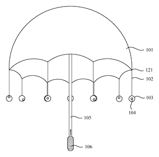
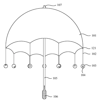
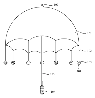
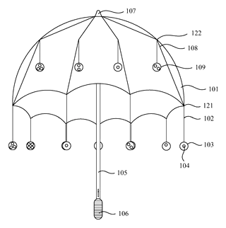
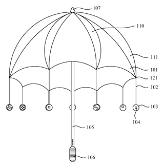
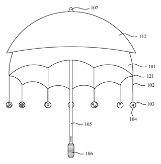
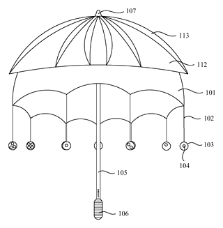
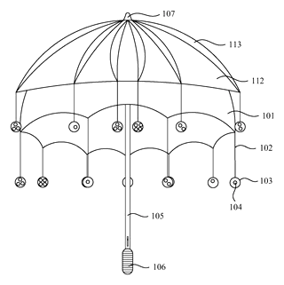
Drawings reproduced from the public patent document for reference.
Frequently asked questions
Are the lights waterproof?
Yes. The patent describes a transparent sealing structure that covers the LED, driver, and battery. This enclosure is designed to protect the internal electronics from rain and moisture.
Why do the lights hang instead of being fixed?
They are suspended by elastic connectors. This allows them to swing as you walk. The movement creates a dynamic light effect that is more visible to drivers and people around you than a static light.
How does the charging work?
The umbrella comes with a storage case. Inside the case is a wireless charging coil. When you put the umbrella in, the blunt tip of the shaft presses a switch. This turns on the charger, which wirelessly powers the battery inside the umbrella.
Can I use any charger with the case?
The case has a specific power adapter plug. You must use the provided adapter or one with matching specifications. The wireless transfer depends on the correct alignment of the coil and the umbrella’s receiving unit.
Do the lights turn on automatically?
Some embodiments include a switch activated by motion or pressure. However, the primary activation method described for charging is the physical insertion into the case. User operation modes may vary by design configuration.
Is the umbrella durable in wind?
The elastic connectors allow the lights to move, which reduces stress on the frame compared to rigid attachments. However, extreme winds may still affect stability. The frame uses standard rib structures matched to the canopy.
Can this design be made and sold in the US?
The patent was filed in China and has lapsed due to non-payment of fees. The public record shows no US counterpart, so it does not restrict the design in the US. However, you must comply with FCC regulations for wireless charging and safety standards for lithium batteries.
Are you affiliated with the patent owner?
No. IP2M is an independent design and manufacturing service working from the public patent document.
Request a quote
Click Request a Quote below to see our email address - copy it, or open your email app with a ready-made message. Please mention patent CN108887818B in the subject.
Helpful details to include:
- Your company and channel (safety gear brand, novelty retailer, corporate gifter)
- LED Element Style (spherical, custom figure, etc.)
- Charging Case Specs (size, material, plug type)
- Estimated quantity and target price
- Timeline - when you would like samples and the first shipment
You can also reach us at (332) 203-9997.
Page editor: Daniel Chen, Product Research Editor · IP2M
Last updated November 8, 2026. If something on this page looks wrong, email [email protected] and we will check it against the patent.
Interested in building this?
Tell us your target market, quantity and timeline. We reply with options for prototyping, small-batch runs or volume production.
Send your inquiry to
Please put CN108887818B in the subject line and tell us your company, country, estimated quantity and timeline.
Prefer to talk? Call (332) 203-9997.
More product-ready patents
All Apparel & Accessories patents →
Apparel & Accessories
Stacked Zipper with Teeth That Mesh Top-to-Bottom
Zipper whose two identical tooth rows mesh on top of each other, closed by a simplified slider.
Patent CN205795062U
Apparel & Accessories
Impact-Resistant Glove with a 3D-Printed Lattice Layer
Work glove with a 3D-printed lattice impact layer, TPU knuckle guards and a light mounting area.
Patent CN213785583U
Apparel & Accessories
Massage Insole with Spring-Back Silicone Nubs and a Removable Top Layer
Layered insole: silicone nubs rise through a removable perforated top sheet and sink under each step.
Patent CN208286505U
Apparel & Accessories
Heel-Less Carbon Plate Running Shoe Sole for Forefoot Strikers
Running sole for forefoot strikers: no ground-touching heel, winged carbon plate between two midsoles.
Patent CN216723354U
Apparel & Accessories
Waterproof Magnetic Zipper Stop That Snaps the Two Halves Together
Separating-zipper stop with sealed magnets: pin and box snap together one-handed, safe in rain and wash.
Patent CN215075936U
Apparel & Accessories
Left-Right Specific Soccer Socks: Grip for the Plant Foot, Touch Pads for the Kicking Foot
Soccer socks knitted as a left-right pair: grip zones for the plant foot, pads for the kicking foot.
Patent CN212728807U
Browse by category
- Apparel & Accessories (51)
- Baby & Kids (30)
- Bags & Luggage (17)
- Bath & Personal Care (33)
- Car Accessories (27)
- Furniture, Bedding & Storage (25)
- Garden & Outdoor (34)
- Health & Wellness (15)
- Home, Kitchen & Cleaning (52)
- Lighting (25)
- Packaging & Containers (13)
- Pet Products (12)
- Phone & Camera Accessories (10)
- Retail Display (27)
- School, Office & Art (38)
- Sports & Recreation (49)
- Tools & Workshop (57)
- Toys & Games (24)
This page is based on the public patent document CN108887818B, assigned to Dongguan Wenyu Industrial Co Ltd. IP2M is an independent manufacturing service and is not affiliated with, endorsed by or licensed by the patent owner. Images marked as concept renderings are illustrations, not photos of an existing product. Patent status information is provided for reference only and is not legal advice; confirm freedom to operate for your market before production. Full disclaimer.