
Patent CN108903195B
Updated November 6, 2026Luggage Rack with a Hidden Seat Plate and Gear-Driven Pin Mechanism
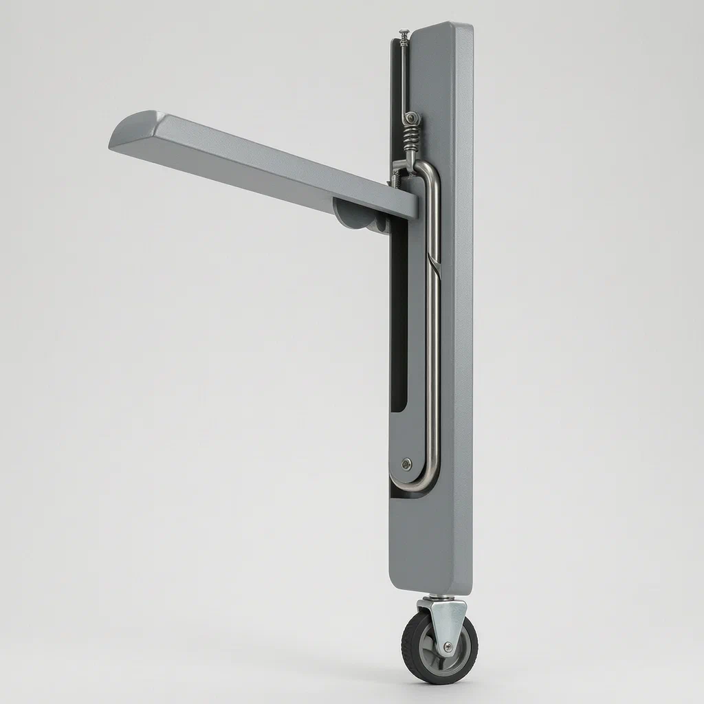
Standard luggage racks offer no seating, forcing guests to stand while unpacking or waiting. This design integrates a fold-out seat directly into the rack structure. Unlike simple hinged seats, this version uses a mechanical locking system driven by a gear and rope mechanism. Pressing a head on top of the rack activates the gear, which retracts a pin to lock the seat plate securely against the frame. This ensures the seat remains stable under load without complex external latches, keeping the profile clean when folded away.
- China invention patent - lapsed
- No filings outside China
- Travel accessories & furniture hardware
- Metal frame, plastic gears, spring-loaded pin locking
Splat! What let you down?
🪑
Integrated Seating
A seat plate rotates out from the side of the rack, providing immediate seating space.
⚙️
Gear-Locked Stability
A pressing head drives a gear and rope system to extend a locking pin into the seat.
🛞
Mobile Base
Universal wheels at the bottom allow easy movement of the loaded rack.
🔒
Compact Storage
The seat folds flat against the frame when not in use, maintaining a slim profile.
Bring this product to market
- ✓ Patent review Patent family and legal status reviewed in the relevant jurisdictions.
- 2 Product brief · now How it works, uses and options written up
- 3 Prototype First samples for buyers to review
- 4 Pilot run Small first batch for launch customers
- 5 Volume production Repeat orders at scale
Buyer interest
– of 100 buyers needed to start prototyping
One click, no sign-up. Each vote is one real visitor, and products with the most interest go to prototyping first.
Build team: no members yet. Need a partner, co-funding or skills to build this? Join and we introduce the team once it forms.
Patent Rights & Team Participation
Before joining a development team, participants should ensure they have the necessary rights or authorization to participate in the project.
Participation is generally appropriate where:
- You own the relevant patent rights or have obtained permission or a license from the rights holder.
- The relevant patent rights have expired or have been legally invalidated in the jurisdictions where the planned activities will take place.
- The planned development, manufacturing, and commercialization activities have been independently assessed and do not infringe applicable patent rights in the relevant jurisdictions.
Important: Being located outside a country where a patent is protected does not automatically exempt you from patent infringement risks. Patent rights may apply based on where development, manufacturing, use, sale, or import activities take place.
IP2M does not grant any patent license or authorization through team participation. Joining a project does not provide permission to use, manufacture, or commercialize patented technology.
The problem
In hotel rooms, event venues, or airport lounges, luggage racks are essential for organizing bags off the floor. However, standard racks do not provide seating. Guests often have to sit on the bed, a chair far away, or remain standing while sorting through their belongings. Adding a separate folding chair creates storage clutter and requires additional floor space. Existing integrated solutions often rely on loose hinges or friction fits that can wobble or fail under weight, creating safety concerns. There is a need for a luggage rack that offers a stable, lockable seat that deploys easily but remains compact when stored.
The solution
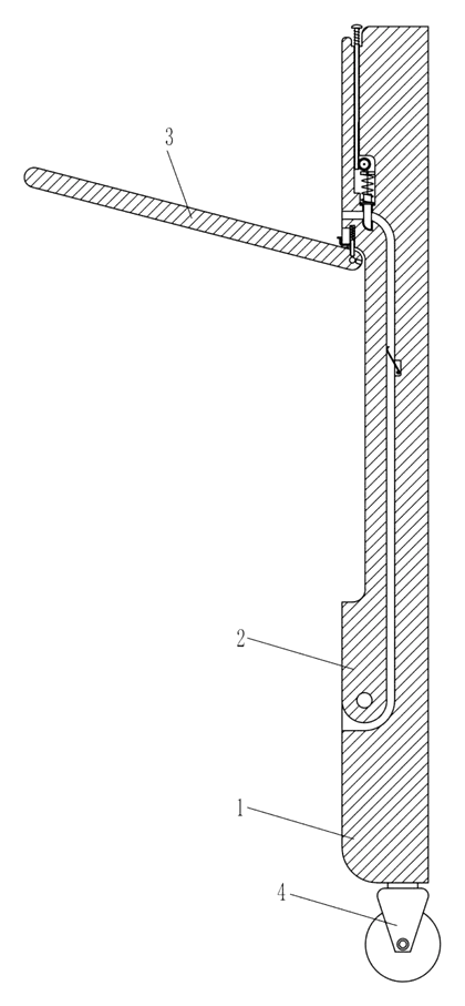
- The core structure is a box frame (1) equipped with universal wheels (4) at the base for mobility.
- A seat plate (2) is rotatably connected to the lower part of the left side surface of the box frame.
- A support plate (3) is attached to the upper part of the seat plate’s left side, likely reinforcing the hinge area or serving as a backrest support depending on orientation.
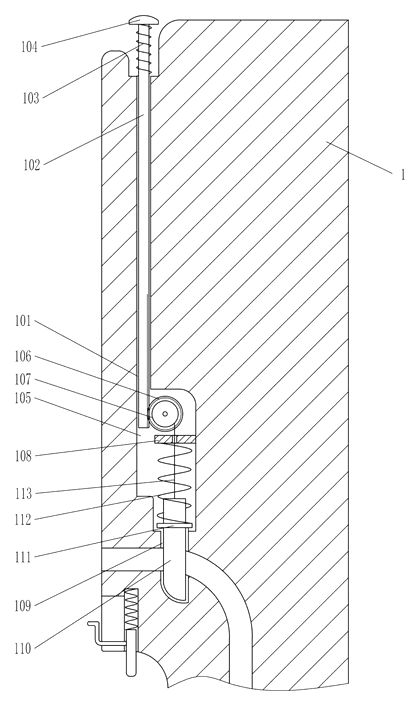
- A vertical guide hole (101) is located on the upper left side of the box frame, housing a rack bar (102).
- The top of the rack bar features a pressing head (104), surrounded by a first spring (103) that returns the head to its raised position.
- Below the guide hole, inside a cavity (105), a gear (106) meshes with the teeth of the rack bar.
- The gear is connected to a winding wheel (107) on its front face. A rope (113) winds around this wheel.
- The rope passes through an orifice plate (108) and connects to the top of a first pin (110).
- The first pin sits in a guide hole (109) below the cavity, assisted by a limit block (111) and a second spring (112) connecting to the orifice plate.
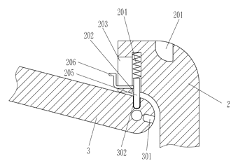
- When the pressing head is depressed, the rack bar moves down, turning the gear. This rotates the winding wheel, pulling the rope up, which raises the first pin into a first clamping groove (201) on the top of the seat plate, locking it open.
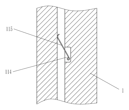
- A spring plate (115) in a groove (114) on the right side of the frame contacts the seat plate to stabilize it.
Who it is for
- Hotel Furniture Suppliers: Brands looking to offer multi-functional room amenities that save space and enhance guest convenience without adding separate chairs.
- Event Rental Companies: Providers needing durable, mobile luggage handling units that also serve as seating for staff or guests during setup and teardown.
- Travel Accessories Manufacturers: Companies targeting frequent travelers who want a portable rack that doubles as a stool in airports or train stations.
- Retail Display Designers: Stores that need display stands for large items like suitcases where customers might want to sit briefly to inspect products.
How it works
The main parts
| No. | Part | What it does |
|---|---|---|
| 1 | Box Frame | Main structural body with wheels. |
| 2 | Seat Plate | Rotates out to form the seat. |
| 3 | Support Plate | Reinforces the seat hinge area. |
| 4 | Universal Wheels | Allows mobility of the unit. |
| 101, 102 | Guide Hole & Rack Bar | Vertical track for the actuator. |
| 104, 103 | Pressing Head & Spring | User interface; returns to rest position. |
| 106, 107 | Gear & Winding Wheel | Converts linear push into rotational pull. |
| 110, 113 | First Pin & Rope | Locking element engaged by the rope. |
| 201 | Clamping Groove | Slot on the seat that receives the pin. |
| 115 | Spring Plate | Stabilizes the seat from the opposite side. |
Operating steps
- Deploy the Seat: Rotate the seat plate (2) outward from the box frame (1) until it reaches the horizontal position.
- Engage the Lock: Press down the pressing head (104) on top of the rack. This pushes the rack bar (102) down.
- Mechanical Transfer: The downward movement of the rack bar turns the gear (106) inside the cavity. The gear rotates the winding wheel (107).
- Pin Engagement: As the winding wheel turns, it pulls the rope (113) upward. This lifts the first pin (110) against the force of the second spring (112).
- Locking: The tip of the first pin enters the first clamping groove (201) on the seat plate, preventing it from rotating back.
- Release: To stow the seat, press the head again or manipulate the release mechanism (implied by the spring return), allowing the pin to drop out of the groove so the seat can be folded back.
Applications
Hotel Guest Rooms
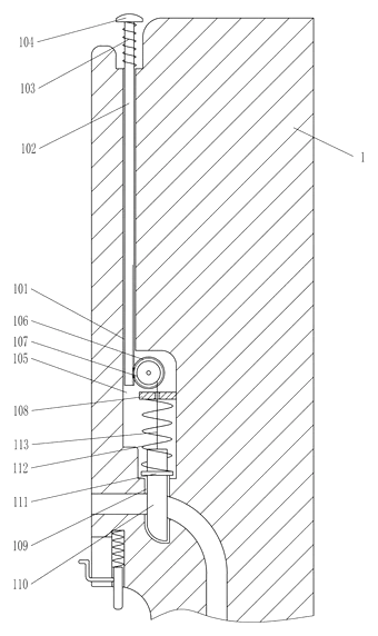
Guests can place their suitcase on the rack and use the fold-out seat to unpack comfortably. It eliminates the need for a bulky armchair if space is limited, keeping the room tidy.
Airport and Train Lounges
Travelers waiting for flights or trains can use these racks to store carry-ons and sit temporarily. The mobility allows staff to rearrange seating clusters easily during peak hours.
Event Staff Areas
During conferences or weddings, staff can use these units to hold equipment cases and take short breaks. The locking mechanism ensures the seat doesn’t collapse unexpectedly under load.
Retail Fitting Rooms
In clothing stores, these racks can hold customer bags while they try on clothes. The seat provides a place to change shoes, improving the fitting experience without permanent installation.
Where it is less suitable
- Heavy Industrial Use: The plastic and light metal components described may not withstand abusive industrial environments compared to steel pallet racks.
- Outdoor Exposure: Without specified weatherproofing materials in the patent text, rain or extreme heat could degrade the rope and springs.
- High-Frequency Public Transit: If used in subways or buses, the manual locking mechanism might be too slow for rapid turnover needs.
Patent & Production
At a glance
| Patent number | CN108903195B (application CN201810761358) |
| Type | China invention patent (发明专利) - protects product structure and method |
| Original title | A luggage rack with a hidden seat plate (一种隐藏座板的箱包架) |
| Patent owner | Nantong An Art Design Co ltd |
| Inventors | Peng Shenglin |
| Filing date | 2018-07-12 |
| Grant date | 2020-02-07 |
| Status (China) | Lapsed - terminated for non-payment of annual fees (recorded 2026-07-17) |
| Patent family | Public record shows Chinese filings only - no US, European, Japanese, PCT or other filings listed |
| Cited by | 0 later documents |
| Source | Google Patents (search for CN108903195B) |
What the claims cover, in plain language
Claim 1 defines a luggage rack comprising a box frame, a seat plate, a support plate, and universal wheels. The seat plate rotates from the lower left side of the frame. The support plate attaches to the seat’s upper left side. The locking mechanism includes a guide hole on the frame’s upper left, containing a rack bar with a pressing head and first spring. A cavity below holds a gear meshing with the rack bar. The gear drives a winding wheel connected by a rope to a first pin housed in a lower guide hole. The pin engages a clamping groove on the seat plate. A spring plate in a right-side groove contacts the seat. Additional elements include a limit block, second spring, and orifice plate. Dependent claims add details about the specific arrangement of the third spring, second pin, and driving lever within the seat plate’s guide slots, suggesting an alternative or enhanced locking configuration involving multiple pins and levers.
This is a simplified reading for orientation only. The legal scope is defined by the exact claim wording in the official Chinese document.
What this means for US production
This patent was filed in China and has lapsed due to non-payment of annual fees, so it no longer restricts anyone in China either. The public record shows no US or other foreign counterpart.
Two points to settle early:
- Other patents may exist. Travel accessories and furniture mechanisms are heavily patented fields. While this specific gear-rope combination appears unique to this filing, similar self-locking luggage racks or convertible furniture may be covered by other US patents held by major manufacturers. A freedom-to-operate (FTO) review is recommended before mass production.
- Material Safety. Since the device involves moving parts and potential pinch points (gears, ropes, pins), compliance with general consumer product safety standards regarding entrapment and sharp edges is critical.
Customization and manufacturing
What can be customized
| Area | Options |
|---|---|
| Frame Material | Aluminum alloy, steel tube, or high-density plastic shell |
| Seat Surface | Upholstered fabric, wood veneer, or molded plastic |
| Wheel Type | Swivel casters with brakes, silent rubber, or hard plastic |
| Locking Mechanism | Adjust gear ratio for easier pressing; replace rope with cable |
| Dimensions | Width and height scaled to fit standard suitcase sizes |
| Finish | Powder coating, anodizing, or fabric color matching |
Things to plan for (US market)
- CPSC Guidelines: General consumer product safety rules apply. Ensure no sharp edges on exposed metal parts and test for pinch hazards in the gear/rack mechanism.
- ASTM Standards: If marketed for children or specific institutional use, relevant ASTM furniture standards (e.g., for stability and durability) should be reviewed.
- California Prop 65: Materials used in plastics and finishes must be screened for restricted chemicals.
How a project runs
- Inquiry - Define target dimensions, load capacity, and aesthetic preferences.
- Design - CAD modeling of the gear-rack interface and seat hinge geometry.
- Prototype - 3D-printed functional mockups to test the locking action and ergonomic feel.
- Pilot Run - Small batch production using injection-molded hardware and assembled frames.
- Production - Full-scale manufacturing with quality control checks on pin engagement and wheel rotation.
Quantities & timeline
Tooling costs depend on whether the frame is welded from tubes or molded as a single piece. Injection molds for the gear and housing components require precision engineering. Assembly involves riveting or screwing the seat plates and installing the internal mechanism. Send us your desired dimensions, material preferences, and estimated volume and we will reply with options.
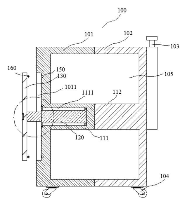
Patent drawings
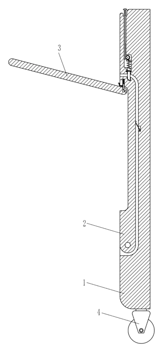
Drawings reproduced from the public patent document for reference.
Production notes
Tooling and process
Likely processes include molded plastic hardware for the gear, winding wheel, and pressing head. The frame may involve aluminum frame extrusion or sewing if fabric-covered panels are used. Zipper assembly might be required if there are storage compartments added. Final assembly typically uses screws and rivets.
Cost drivers
Costs are typically driven by the hardware complexity (precision gears) and shell material choice. Fabric and zipper grade impacts cost if textile components are included. Packaging size affects shipping logistics.
Prototyping path
We would start with a sewn first sample if fabric is involved, alongside 3D-printed or machined hardware for the mechanism. Conduct a wheel and handle test for mobility. Build a functional sample to verify the locking pin engagement. Create production patterns for any soft goods.
What we would change before tooling
We would likely refine the shaft and bearing alignment of the gear to reduce friction noise. Testing spring fatigue and rate consistency is crucial to ensure the locking mechanism remains reliable over thousands of cycles.
Common failure points
Potential issues likely include zipper pull breakage if zippers are used, handle detachment from the frame, or wheel wear on rough surfaces. Seam failure is a risk for any upholstered parts. The motor mount cracking is not applicable here as it is a manual device, but frame distortion under heavy loads is a concern.
Frequently asked questions
How does the seat lock in place?
The seat is secured by a mechanical pin system. When you press the head on top of the rack, a rack bar moves down, turning a gear. This gear pulls a rope that lifts a pin into a groove on the seat plate, holding it firmly in the open position.
Is the seat stable enough for adults?
The patent describes a locking mechanism designed to prevent the seat from collapsing. Stability depends on the final material choices (metal vs. plastic) and the load rating set in design. We recommend testing prototypes to confirm weight limits.
Can the seat be removed or adjusted?
The seat plate is rotatably connected to the frame. It is designed to fold flat against the side when not in use. Adjustment angles are fixed by the locking pin position; custom designs could allow multiple locking positions.
What materials are used for the frame?
The patent mentions a “box frame” and “support plate,” typically implying metal (steel or aluminum) or durable plastic. Specific materials are chosen during the design phase based on cost and strength requirements.
Does it work with all suitcase sizes?
The rack is sized to accommodate standard luggage. Larger suitcases may overhang. Dimensions can be customized to fit specific bag sizes, such as carry-on or checked baggage standards.
Is the locking mechanism difficult to operate?
It requires a simple press of the head. The force needed depends on the spring tension and gear ratio. In most designs, it is intended to be user-friendly for hotel staff or travelers.
Can this design be made and sold in the US?
The patent was filed in China and has lapsed, and the public record shows no US counterpart, so it does not restrict the design in the US or in China. However, other patents may exist in this field, so we recommend a freedom-to-operate check before volume production.
Are you affiliated with the patent owner?
No. IP2M is an independent design and manufacturing service working from the public patent document.
Request a quote
Click Request a Quote below to see our email address - copy it, or open your email app with a ready-made message. Please mention patent CN108903195B in the subject.
Helpful details to include:
- Your company and channel (hotel supplier, event rental, retail brand)
- Target dimensions and load capacity
- Preferred materials (metal, plastic, upholstery)
- Features (brakes on wheels, additional storage pockets)
- Estimated quantity and target price
- Timeline - when you would like samples and the first shipment
You can also reach us at (332) 203-9997.
Page editor: Emily Zhang, Product Editor · IP2M
Last updated November 6, 2026. If something on this page looks wrong, email [email protected] and we will check it against the patent.
Interested in building this?
Tell us your target market, quantity and timeline. We reply with options for prototyping, small-batch runs or volume production.
Send your inquiry to
Please put CN108903195B in the subject line and tell us your company, country, estimated quantity and timeline.
Prefer to talk? Call (332) 203-9997.
More product-ready patents
All Bags & Luggage patents →
Bags & Luggage
Quick-Access Luggage with Fold-Down Back Compartment
Hard-shell suitcase with a fold-down compartment in the back panel for phone, passport and power bank - no need to open the case.
Patent CN210076793U
Bags & Luggage
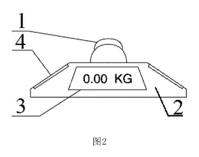
Luggage Handle with Built-In Scale
Suitcase carry handle with a built-in weighing sensor and display - lift the bag and read its weight.
Patent CN206670777U
Bags & Luggage
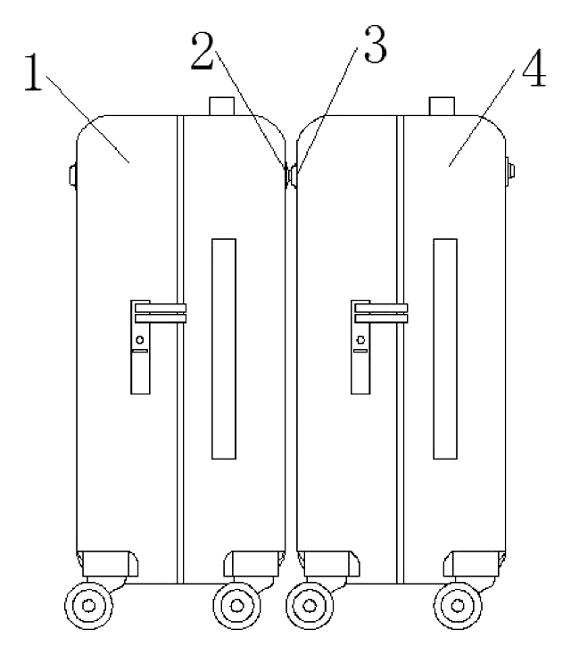
Snap-Together Luggage Connector
Stud-and-socket snap built into suitcases so two cases lock together and roll with one hand.
Patent CN209862619U
Bags & Luggage
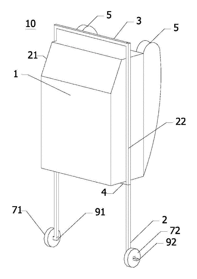
Side-Rail Rolling Backpack with Raised Wheels
Rolling backpack with pull rails on the sides, not the back, and rails that lower the wheels.
Patent CN207733803U
Bags & Luggage
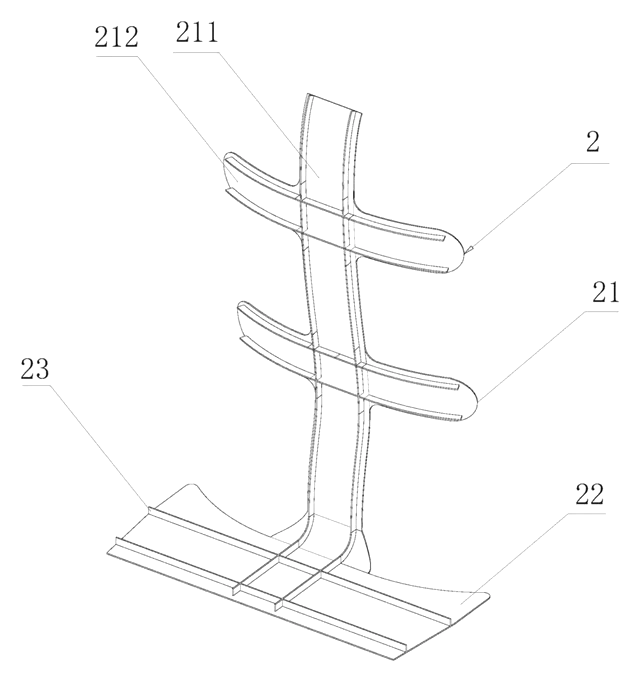
Backpack with Removable Body-Shaped Inner Frame
Backpack with a lift-out inner frame shaped to the back that spreads the load to the back and hips.
Patent CN216534262U
Bags & Luggage
Hard-Shell Luggage Case with a Built-In Lift Table
Hard-shell luggage with a telescopic rod and desktop that rises from the lid.
Patent CN107485137B
Browse by category
- Apparel & Accessories (43)
- Baby & Kids (28)
- Bags & Luggage (16)
- Bath & Personal Care (29)
- Car Accessories (23)
- Furniture, Bedding & Storage (22)
- Garden & Outdoor (29)
- Health & Wellness (13)
- Home, Kitchen & Cleaning (46)
- Lighting (22)
- Packaging & Containers (11)
- Pet Products (10)
- Phone & Camera Accessories (9)
- Retail Display (23)
- School, Office & Art (33)
- Sports & Recreation (41)
- Tools & Workshop (50)
- Toys & Games (21)
This page is based on the public patent document CN108903195B, assigned to Nantong An Art Design Co ltd. IP2M is an independent manufacturing service and is not affiliated with, endorsed by or licensed by the patent owner. Images marked as concept renderings are illustrations, not photos of an existing product. Patent status information is provided for reference only and is not legal advice; confirm freedom to operate for your market before production. Full disclaimer.