
Patent CN109177897B
Updated October 28, 2026Anti-Tamper Automobile License Plate Frame with Gear-Driven Fastening Plates
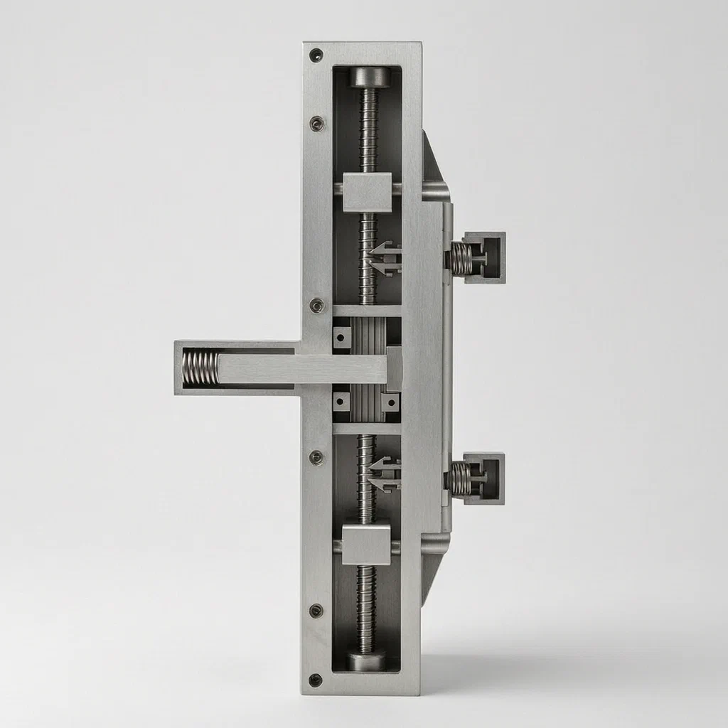
Standard license plate frames rely on exposed screws that can be removed with basic tools, leaving plates vulnerable to unauthorized detachment or shielding. This frame addresses that issue by enclosing the fastening action inside a working cavity within the fixing plate. When the internal power gear turns, it drives front and rear racks, which in turn move connecting rods attached to front and rear fastening plates. Simultaneously, adjusting rings threaded onto upper and lower threaded rods push driving rods that advance upper and lower fastening plates. Together, these four plates clamp the license plate from all sides. Because the mechanism operates inside the fixing plate and uses interlocking gears, racks and threaded components, accessing or reversing the fastening process requires specific interaction with the internal parts rather than simply turning visible bolts.
- China invention patent - in force
- No filings outside China
- Automotive accessories
- Gear, rack and threaded rod mechanism
Splat! What let you down?
⚙️
Internal gear mechanism
A power gear inside the fixing plate drives front and rear racks to move fastening plates simultaneously.
🔒
Four-sided clamping
Upper, lower, front and rear fastening plates press against the license plate from all directions.
🔩
Threaded adjustment
Adjusting rings on threaded rods convert rotation into linear motion for the upper and lower plates.
🛡️
Enclosed working cavity
The fastening components sit inside the fixing plate, reducing access to the securing mechanism.
Bring this product to market
- ✓ Patent vetted China-only family and legal status checked
- 2 Product brief · now How it works, uses and options written up
- 3 Prototype First samples for buyers to review
- 4 Pilot run Small first batch for launch customers
- 5 Volume production Repeat orders at scale
Buyer interest
– of 100 buyers needed to start prototyping
One click, no sign-up. Each vote is one real visitor, and products with the most interest go to prototyping first.
Build team: no members yet. Need a partner, co-funding or skills to build this? Join and we introduce the team once it forms.
The problem
Standard license plate frames typically use exposed screws or simple clips to hold a plate against a vehicle bumper or trunk. These fasteners are easily reached with common hand tools, making it straightforward for someone to remove or swap a plate without authorization. Additionally, flat frames offer little resistance if someone attempts to place a cover or shield over the plate to obscure the characters. Fleet operators, dealerships and individual owners face ongoing issues with plate theft, unauthorized swapping and accidental detachment caused by vibration loosening standard hardware. A frame that relies solely on external bolts cannot provide sufficient security against deliberate tampering.
The solution
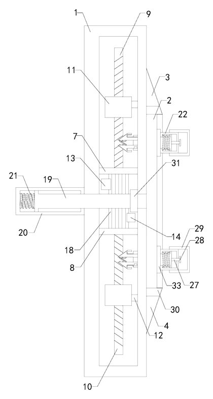
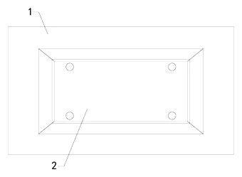
This patent describes an automobile license plate frame that encloses its fastening mechanism within a working cavity inside a fixing plate (1). Instead of relying on exposed screws through the plate itself, the system uses a combination of gears, racks, threaded rods and springs to clamp the license plate (2) from four sides.
- The license plate (2) features four groups of fixing holes on its upper front, lower front, upper rear and lower rear areas.
- Inside the fixing plate (1), a power gear (18) meshes with a front rack (13) and a rear rack (14). When the gear turns, it pushes the racks in opposite directions.
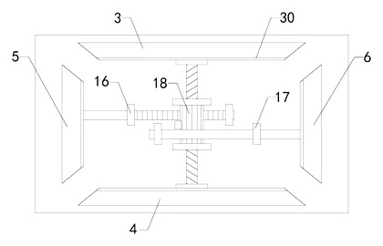
- Connecting rods (15) link the racks to a front fastening plate (5) and a rear fastening plate (6), sliding through transverse holes in the working cavity.
- An upper threaded rod (9) and a lower threaded rod (10) pass through adjusting rings (11) that have opposing internal threads. Turning the threaded rods moves driving rods (12) that push an upper fastening plate (3) and a lower fastening plate (4) toward the plate.
- Limiting rings (7, 8, 16, 17) guide the rods and keep them aligned within the cavity.
- A pushing rod (20) with a telescopic cavity, a driving rack (19) and a limiting spring (21) interact with the gear assembly to actuate the mechanism. Four groups of clamping rods, mounting pipes, pushing springs and baffles further secure the frame to the vehicle.
Who it is for
- Fleet management companies operating delivery vans, rental cars or corporate vehicles that need to prevent drivers or third parties from removing or swapping plates between assignments.
- Automotive dealerships that display inventory on lots where plates or temporary tags are vulnerable to theft or unauthorized exchange overnight.
- Commercial vehicle upfitters building work trucks who want to integrate a more secure plate mounting system directly into custom bumpers or body panels.
- Aftermarket auto accessory brands looking to add a mechanically complex, tamper-resistant frame to their catalog for security-conscious retail buyers.
How it works
The main parts
| No. | Part | What it does |
|---|---|---|
| 1 | Fixing plate | Houses the working cavity and mounts to the vehicle. |
| 2 | License plate | Held by the fastening plates; has four groups of fixing holes. |
| 3, 4 | Upper / lower fastening plates | Clamp the top and bottom edges of the license plate. |
| 5, 6 | Front / rear fastening plates | Clamp the front and rear areas of the license plate. |
| 7, 8 | Upper / lower limiting rings | Guide the threaded rods vertically. |
| 9, 10 | Upper / lower threaded rods | Drive the adjusting rings when rotated. |
| 11 | Adjusting rings | Convert threaded rod rotation into linear movement via driving rods. |
| 12 | Driving rods | Transfer motion from adjusting rings to upper/lower fastening plates. |
| 13, 14 | Front / rear racks | Mesh with the power gear to move connecting rods horizontally. |
| 15 | Connecting rods | Link the racks to the front and rear fastening plates. |
| 16, 17 | Front / rear limiting rings | Guide the connecting rods within the cavity. |
| 18 | Power gear | Central gear that drives the front and rear racks. |
| 19 | Driving rack | Interacts with the mechanism through the extrusion port. |
| 20 | Pushing rod | Contains a telescopic cavity to actuate the internal parts. |
| 21 | Limiting spring | Provides return force or tension within the assembly. |
Operating steps
- The license plate (2) is positioned against the fixing plate (1), aligning its four groups of fixing holes with the internal mechanism.
- Actuation of the pushing rod (20) or driving rack (19) engages the power gear (18) inside the working cavity.
- The power gear (18) rotates, pushing the front rack (13) and rear rack (14) outward along their transverse sliding holes.
- The moving racks pull the connecting rods (15), which draw the front fastening plate (5) and rear fastening plate (6) tightly against the license plate.
- Simultaneously, the gear action or linked components rotate the upper threaded rod (9) and lower threaded rod (10).
- The adjusting rings (11), threaded in opposite directions, travel along the rods and push the driving rods (12) through the longitudinal sliding holes.
- The driving rods force the upper fastening plate (3) and lower fastening plate (4) inward, completing the four-sided clamp.
- The limiting spring (21), clamping rods, mounting pipes, pushing springs and baffles lock the components in place, resisting reverse movement.
Applications
Fleet vehicle security
Delivery and logistics companies manage hundreds of vehicles where plates may be targeted for unauthorized use. This frame encloses the fastening hardware, requiring specific mechanical interaction to release the plate, which deters opportunistic removal during stops or overnight parking.
Dealership lot management
Car dealerships frequently attach temporary or inventory plates to vehicles parked outdoors. Standard screws are easy targets after hours. The four-sided clamping action and enclosed working cavity reduce the risk of plates being detached or swapped between vehicles on the lot.
Commercial work trucks
Vehicles used in construction or utility services endure heavy vibration that can loosen conventional bolts. The internal gear and rack system, supported by limiting rings and springs, maintains constant pressure on the plate, keeping it seated even under continuous road shock.
Municipal and government vehicles
Public service vehicles require strict plate compliance and tracking. By making unauthorized detachment mechanically difficult, fleet managers can better ensure that assigned plates remain on their designated vehicles throughout their service life.
High-theft urban parking
Drivers in dense urban areas often face plate theft for use on unregistered vehicles. A frame that hides its actuation mechanism behind a solid fixing plate removes the obvious screw heads that thieves target with basic tools.
Where it is less suitable
- Temporary paper tags - the mechanism is designed around rigid plates with specific hole patterns; flimsy paper dealer tags may not withstand the clamping force.
- Minimalist aesthetic preferences - the internal cavity and multiple rods require a thicker fixing plate than a slim, flat surround frame.
- Rapid-swap track vehicles - users who change plates daily for off-road or track events will find the multi-step gear mechanism slower than quick-release pins.
Frequently asked questions
How does the frame hold the license plate?
Instead of passing screws directly through the plate, this frame uses four internal fastening plates that press against the top, bottom, front and rear edges of the license plate. A power gear inside the fixing plate drives racks and threaded rods to push these fastening plates inward simultaneously, clamping the plate securely.
Can someone just unscrew it with a regular screwdriver?
The primary fastening components sit inside an enclosed working cavity within the fixing plate. The actuation relies on a pushing rod and driving rack interacting with the internal gear. Without access to the specific actuation point or tool designed for the pushing rod, reversing the gear mechanism to release the clamping plates is difficult compared to turning exposed bolts.
Will this fit standard US license plates?
The patent describes four groups of fixing holes on the license plate. For US production, the spacing of these holes, the length of the fastening plates and the overall dimensions of the fixing plate must be set in design to match the standard 12-by-6-inch US plate format and confirmed on prototypes.
What materials can it be made from?
The patent text does not specify materials. For automotive exterior use, the fixing plate and fastening components are typically produced from aluminum alloy, stainless steel or zinc alloy to handle road conditions, with the internal gears and rods machined from hardened metals.
Does the mechanism rattle while driving?
The design includes a limiting spring, pushing springs and baffles within the working cavity. These components are intended to maintain tension and fill gaps between the moving rods and the cavity walls, which reduces vibration noise. The exact spring rates are set in design and confirmed on prototypes.
Is it weatherproof?
The working cavity is enclosed inside the fixing plate, and the patent mentions baffles among the components. To prevent water and road salt from corroding the internal gears and threaded rods, additional rubber seals or drainage channels are planned during the engineering phase for the target market.
Can this design be made and sold in the US?
The patent was filed only in China and is currently in force there. It has no US counterpart, so it does not restrict manufacturing or sales in the United States. However, other companies may hold US patents related to license plate frames or locking mechanisms - see Patent & Production - so a freedom-to-operate check is recommended before volume production.
Are you affiliated with the patent owner?
No. IP2M is an independent design and manufacturing service working from the public patent document.
Request a quote
Click Request a Quote below to see our email address - copy it, or open your email app with a ready-made message. Please mention patent CN109177897B in the subject.
Helpful details to include:
- Your company and channel (fleet supplier, dealership equipment provider, aftermarket brand, commercial upfitter)
- Target vehicle types (passenger cars, light trucks, commercial vans)
- Preferred materials and finish
- Estimated quantity and target price
- Timeline - when you would like samples and the first shipment
You can also reach us at (332) 203-9997.
Explore this product
Interested in building this?
Tell us your target market, quantity and timeline. We reply with options for prototyping, small-batch runs or volume production.
Send your inquiry to
Please put CN109177897B in the subject line and tell us your company, country, estimated quantity and timeline.
Prefer to talk? Call (332) 203-9997.
More product-ready patents
All Car Accessories patents →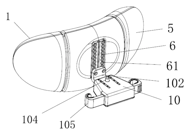
Car Accessories
Car Headrest Pillow with Ratchet Side Wings and Push-Button Reach
Post-mounted car headrest pillow with ratchet side wings and a push-button forward adjustment.
Patent CN212195197U
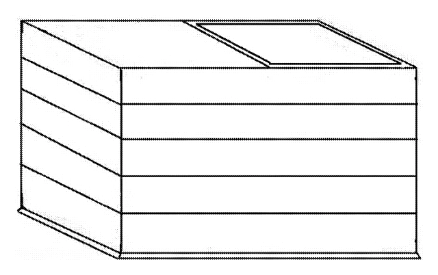
Car Accessories
Hard-Shell Rooftop Tent That Doubles as a Cargo Box
Roof box whose hard frames lift on gas struts into a tent with door and skylight, and fold back for luggage.
Patent CN206327275U
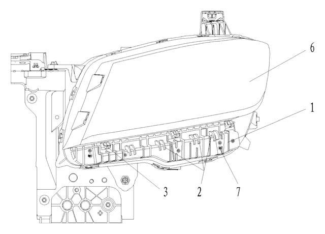
Car Accessories
Headlamp-to-Bumper Adapter Bracket That Sets Gap and Flush in Three Directions
Molded bracket under the headlamp: support blocks and snap teeth locate the bumper flange for an even gap.
Patent CN216580316U
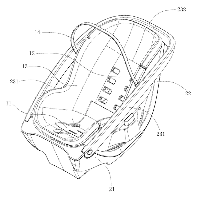
Car Accessories
Infant Car Seat with a Load-Bearing Base That Wraps the Carrier
Infant car seat whose base has a backrest and swing-up side rails, so the carrier can be lighter.
Patent CN206383856U
Car Accessories
Retractable Side Impact Protection Block for Child Car Seats
Retractable side-impact block for child seats: springs out to provide side-impact buffering, folds flat.
Patent CN207028930U
Car Accessories
Rain-Deflecting Side Mirror with a Pivoting Air-Guide Plate
Side mirror with a top air duct and folding guide plate that directs airflow across the glass.
Patent CN207345672U
Browse by category
- Apparel & Accessories (22)
- Baby & Kids (16)
- Bags & Luggage (9)
- Bath & Personal Care (16)
- Car Accessories (10)
- Furniture, Bedding & Storage (12)
- Garden & Outdoor (18)
- Health & Wellness (8)
- Home, Kitchen & Cleaning (24)
- Lighting (12)
- Packaging & Containers (6)
- Pet Products (6)
- Phone & Camera Accessories (4)
- Retail Display (13)
- School, Office & Art (19)
- Sports & Recreation (25)
- Tools & Workshop (27)
- Toys & Games (12)
This page is based on the public patent document CN109177897B, assigned to Cai Haiqiang. IP2M is an independent manufacturing service and is not affiliated with, endorsed by or licensed by the patent owner. Images marked as concept renderings are illustrations, not photos of an existing product. Patent status information is provided for reference only and is not legal advice; confirm freedom to operate for your market before production. Full disclaimer.