
Patent CN110812826B
Updated November 7, 2026Portable Hand-Controlled Hydraulic Wheeled Shoe Vehicle
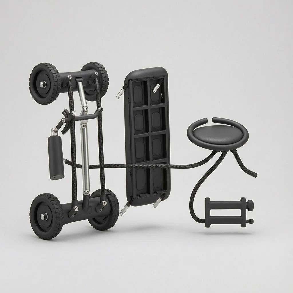
Traditional motorized skates require complex battery systems or heavy mechanical linkages. This patent describes a portable wheeled shoe vehicle powered by hydraulic transmission controlled directly by the hands. The user wears roller-shoe assemblies connected to hydraulic drivers at each foot. A handheld controller operates dual oil cylinders; squeezing the grip drives pistons which push fluid through reinforced hoses to the foot units. A separate relay controller distributes pressure between left and right feet. Braking is managed by a dedicated release button that engages locking mechanisms on the axles. This setup allows for compact, portable mobility devices where upper-body strength replaces lower-body effort for propulsion.
- China invention patent - active
- No filings outside China
- Hydraulic transmission
- Hand-controlled mobility device
Splat! What let you down?
🤲
Hand-driven propulsion
Squeeze a grip to activate hydraulic pistons that turn the wheels; no leg pumping required.
⚖️
Relay hydraulic control
A central box distributes fluid pressure independently to left and right foot drivers.
🛑
Mechanical locking brakes
Brake pads engage via connecting rods and locks when the release button is pressed.
🔗
Modular assembly
Shoes, drivers, and controllers connect via standardized hoses and outer sleeves.
Bring this product to market
- ✓ Patent review Patent family and legal status reviewed in the relevant jurisdictions.
- 2 Product brief · now How it works, uses and options written up
- 3 Prototype First samples for buyers to review
- 4 Pilot run Small first batch for launch customers
- 5 Volume production Repeat orders at scale
Buyer interest
– of 100 buyers needed to start prototyping
One click, no sign-up. Each vote is one real visitor, and products with the most interest go to prototyping first.
Build team: no members yet. Need a partner, co-funding or skills to build this? Join and we introduce the team once it forms.
Patent Rights & Team Participation
Before joining a development team, participants should ensure they have the necessary rights or authorization to participate in the project.
Participation is generally appropriate where:
- You own the relevant patent rights or have obtained permission or a license from the rights holder.
- The relevant patent rights have expired or have been legally invalidated in the jurisdictions where the planned activities will take place.
- The planned development, manufacturing, and commercialization activities have been independently assessed and do not infringe applicable patent rights in the relevant jurisdictions.
Important: Being located outside a country where a patent is protected does not automatically exempt you from patent infringement risks. Patent rights may apply based on where development, manufacturing, use, sale, or import activities take place.
IP2M does not grant any patent license or authorization through team participation. Joining a project does not provide permission to use, manufacture, or commercialize patented technology.
The problem
Motorized personal transport often relies on batteries, electric motors, or complex mechanical linkages that add weight and maintenance needs. Foot-powered scooters require significant leg strength and coordination, which can be difficult for users seeking low-effort mobility. Existing hydraulic applications in footwear are rare due to the difficulty of miniaturizing pumps and valves while maintaining sufficient torque to move a person. Furthermore, controlling speed and braking simultaneously without looking down or shifting body weight remains a challenge for safe operation in crowded environments. There is a need for a simple, robust system that decouples the propulsion effort from the legs, placing it in the hands where fine motor control is easier, while ensuring stable braking through mechanical locks rather than friction-only methods.
The solution
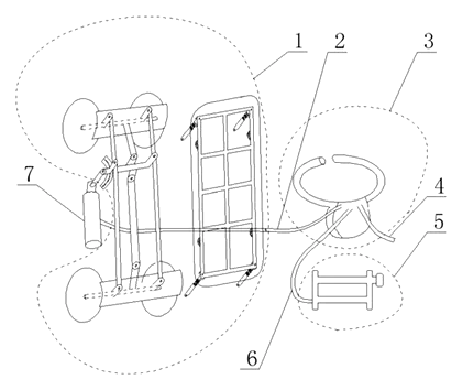
The patent describes a portable hand-controlled bicycle shoe vehicle consisting of four main subsystems: the roller shoe part (1), the hydraulic driver (7), the relay hydraulic controller (3), and the handle controller (5).
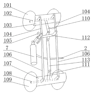
- Roller Shoe Part (1): Each foot unit contains front and rear wheels (101, 109) mounted on axles. Brake pads (103, 107) are attached to these wheels. A driving shaft (112) connects to the hydraulic piston rod. Linkages (C, D, E) transfer motion from the chassis to the axles.
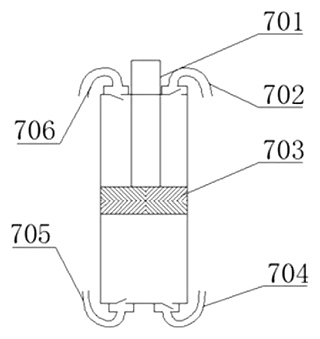
- Hydraulic Driver (7): Located near the ankle or heel, this unit houses a piston (703) connected to the driving shaft. It receives fluid pressure via hoses to rotate the wheels.
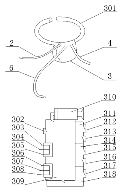
- Relay Hydraulic Controller (3): A central box containing an oil storage reservoir (309) and multiple ports. It manages the flow of hydraulic fluid between the hand controller and the two foot drivers, allowing independent or synchronized operation.
- Handle Controller (5): Held by the user, this unit features two oil cylinders (B, C) with pistons driven by a movable grip rod (509). A brake release button (512) controls valves that disengage the foot brakes.
Who it is for
- Recreational Mobility Brands: Companies looking to expand their product lines beyond electric scooters into manual-hydraulic alternatives for niche markets.
- Industrial Safety Equipment Makers: Manufacturers needing mobile tools where workers must keep hands free for tasks but still require quick relocation capabilities.
- Educational Robotics Kits: Designers creating advanced STEM kits that demonstrate hydraulic principles in a wearable context.
- Prototype Innovators: Inventors exploring human-powered exoskeleton concepts who need a baseline structure for hand-driven lower-limb assistance.
How it works
The main parts
| No. | Part | What it does |
|---|---|---|
| 1 | Roller Shoe Part | Contains wheels, axles, brake pads, and linkage arms. |
| 2, 4, 6 | Outer Sleeves | Protective casings for the hydraulic hoses (M, N, P). |
| 3 | Relay Hydraulic Controller | Central distribution box with oil reservoir and check valves. |
| 5 | Handle Controller | Hand-held unit with dual cylinders and brake release button. |
| 7 | Hydraulic Driver | Piston mechanism at each foot that converts fluid pressure to rotation. |
| 101, 109 | Wheels | Front and rear rollers providing ground contact. |
| 103, 107 | Brake Pads | Friction elements that stop wheel rotation when engaged. |
| 112 | Driving Shaft | Connects the hydraulic piston to the wheel axle. |
| 309 | Oil Storage Box | Reservoir within the relay controller holding hydraulic fluid. |
Operating steps
- Propulsion: The user squeezes the movable grip rod (509) on the handle controller (5). This pushes pistons in cylinders B and C, forcing hydraulic fluid through hoses into the relay controller (3).
- Distribution: The relay controller directs fluid through specific ports to the hydraulic drivers (7) at each foot. Check valves ensure one-way flow to prevent back-pressure.
- Rotation: Fluid pressure extends the piston A (703) in the foot driver, turning the driving shaft (112) and rotating the wheels via linkages.
- Braking: When the user presses the brake release button (512), valves open to relieve pressure or engage mechanical locks, causing the brake pads (103, 107) to clamp onto the wheels.
Applications
Recreational skating alternatives
Users seeking a break from traditional skateboarding can use this device for low-impact exercise. The hand-driven mechanism allows individuals with limited leg strength to enjoy rolling mobility.
Warehouse floor navigation
Workers in large warehouses can move quickly between stations without carrying heavy carts. The hydraulic system provides quiet operation compared to electric motors, reducing noise pollution in indoor environments.
Educational demonstration models
Engineering schools can use simplified versions to teach students about hydraulic circuits, check valves, and mechanical advantage. The modular nature of the patents components makes it ideal for disassembly and study.
Assistive mobility prototypes
Designers exploring hybrid human-machine interfaces can adapt the hand-control logic for users who cannot operate standard pedals. It serves as a base for testing upper-body-driven locomotion.
Where it is less suitable
- High-speed commuting: The hydraulic resistance limits top speed compared to electric motors.
- Rough terrain: Small roller wheels and rigid linkages struggle with uneven surfaces like gravel or grass.
- Long-distance travel: Requires continuous physical effort from the hands, leading to fatigue over extended periods.
Patent & Production
At a glance
| Patent number | CN110812826B (application CN201911000538) |
| Type | China invention patent - protects method and structure |
| Original title | Portable hand-controlled bicycle shoe vehicle (一种便携式手控自行鞋车) |
| Patent owner | Individual |
| Inventors | Duan Guogong |
| Filing date | 2019-10-21 |
| Grant date | 2021-05-25 |
| Status (China) | In force - valid until at most 2039-10-21 if annual fees are paid |
| Patent family | Public record shows Chinese filings only - no US, European, Japanese, PCT or other filings listed |
| Cited by | 0 later documents |
| Source | Google Patents (search for CN110812826B) |
What the claims cover, in plain language
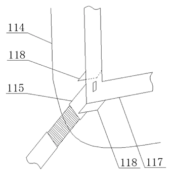
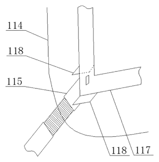
Claim 1 defines the overall system: a portable vehicle comprising roller shoe parts (1), a relay hydraulic controller (3), a handle controller (5), and hydraulic drivers (7). Two sets of shoes and drivers correspond to left and right feet. The hydraulic driver’s rod connects to the shoe’s driving shaft. Hoses run through protective outer sleeves to the relay controller, which connects to the handle. The shoe part includes front/rear wheels, brake pads, and a linkage system (rods A-E) that translates the shaft’s rotation into braking action. A bottom frame supports the chassis with spring rods allowing 15-20 degrees of articulation.
Claim 2 details the hydraulic driver: rubber tubes connect to the front and rear ends of the cylinder via one-way valves. A piston inside drives the external rod. Outer sleeves protect the tubing.
Claim 3 specifies the relay hydraulic controller: an oil storage box with multiple ports (A1, A2, B1, B2, C, D, E, F, G, H, I, K) arranged around zones A, B, and C. Check valves manage flow direction. A micro air cylinder pressurizes the reservoir. Hanging rings allow attachment to clothing or belts.
Claim 4 describes the handle controller: an elastic rubber shell encloses two oil cylinders with pistons linked to a grip rod. A brake release button controls bidirectional single-opening valves. Specific hose connections link the hand unit to the relay controller’s ports.
This is a simplified reading for orientation only. The legal scope is defined by the exact claim wording in the official Chinese document.
What this means for US production
This patent was filed in China and is currently in force. The public record shows no US or other foreign counterpart. Making or selling this specific hydraulic configuration in China requires the owner’s permission. In the US, the lack of a local patent means this specific design is not restricted by this document alone. However, general safety standards apply.
Two points to settle early:
- Other patents may exist. Personal mobility devices and hydraulic actuation systems are broad fields. While this specific combination of hand-control and shoe-mounting appears unique in the public record, broader patents on “wearable actuators” or “hand-operated vehicles” could exist. A freedom-to-operate (FTO) review is recommended before mass production.
- Component sourcing. The relay controller and handle unit require precision machining for valve seats and seals. Off-the-shelf hydraulic components may not match the specific port layout described in Claim 3.
Customization and manufacturing
What can be customized
| Area | Options |
|---|---|
| Fluid Type | Standard hydraulic oil vs. biodegradable ester-based fluids |
| Hose Length | Adjustable lengths based on user height and arm reach |
| Wheel Material | PU casters, rubber treads, or hard plastic for different surfaces |
| Controller Ergonomics | Grip shape, button placement, and housing color |
| Mounting System | Strap-on shoe adapters vs. integrated boot shells |
| Valve Configuration | Single-stage vs. multi-stage pressure regulation |
Things to plan for (US market)
- CPSC Regulations: If marketed as a toy or children’s product, ASTM F963 applies. For general recreational use, standard product liability laws apply.
- Battery Exclusion: This design uses mechanical/hydraulic power, avoiding UN 38.3 battery transport rules, simplifying logistics.
- Material Safety: Ensure all plastics (nylon housings, rubber grips) meet California Prop 65 requirements for phthalates and heavy metals.
- Sharp Edges: Mechanical linkages and brake pads must be guarded to prevent pinch injuries per general safety guidelines.
How a project runs
- Inquiry - Define target user group, desired speed range, and aesthetic preferences.
- Design - CAD modeling of hydraulic circuit, valve mapping, and ergonomic handle layout.
- Prototype - Machined aluminum frames, custom-molded nylon housings, and functional hydraulic test rigs.
- Testing - Leak tests, cycle life testing of seals, and brake engagement reliability checks.
- Production - Injection molding for housings, CNC machining for pistons/shafts, and assembly line integration.
Quantities & timeline
Tooling costs are driven by the number of molds required for the shoe shells, controller housings, and internal valve bodies. Hydraulic seal selection impacts lead time. Send us your target price, volume estimates, and feature list and we will reply with options.
Patent drawings
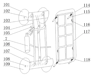
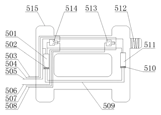
Drawings reproduced from the public patent document for reference.
Production notes
Tooling and process
Likely processes include glass-filled nylon injection molding for the controller housings and shoe shells to withstand impact. Aluminum extrusion is typically used for the chassis rails and shafts. Stamping may be employed for brake pad plates and small linkage brackets. Assembly relies heavily on snap-fit for covers and bolts for high-stress joints.
Cost drivers
Number of molds is a primary cost factor, given the complexity of the relay controller and handle unit. Impact grade material costs vary by resin choice. Fastener count affects assembly labor time. Weight reduction requires thinner walls, increasing tooling complexity. Packaging must protect protruding hydraulic hoses. Actual costs typically depend on final materials, order volume, and supplier quotes.
Prototyping path
Start with 3D-printed parts for form and fit verification. Use machined frames for early hydraulic function tests. Create impact test samples to validate nylon durability. Build a functional sample with real seals to check leak rates. Finalize tooling after design validation. The exact sequence depends on the final design and supplier feedback.
What we would change before tooling
Depends on the final design, but hinge boss and pivot wear is a risk; consider hardened steel inserts. Wall thickness and joint design in the shoe shell may need reinforcement to prevent cracking under impact. Spring fatigue and rate consistency in the suspension rods should be tested rigorously.
Common failure points
Cracking under impact is likely if nylon is too brittle. Bolts loosening in the linkage area can alter brake alignment. UV degradation affects rubber hoses and grips. Shaft and bearing alignment errors cause drag. Motor mount cracking is not applicable here, but piston seal failure is critical.
Frequently asked questions
How does the hand control work?
You squeeze a grip on the handheld unit. This moves pistons in two cylinders, pushing hydraulic fluid through hoses to the shoes. The fluid pressure turns a piston in the foot unit, which rotates the wheels. A separate button releases the brakes.
Do I need batteries or electricity?
No. The system is purely mechanical and hydraulic. It uses fluid pressure generated by your hand movements to propel the wheels. There are no motors, wires, or batteries involved.
Is it difficult to balance?
The design includes a bottom frame with spring rods that allow some articulation (15-20 degrees). This helps stabilize the shoe on the foot. However, like any new mobility device, practice is needed to coordinate hand squeezing with body positioning.
Can I customize the look?
Yes. The outer shells can be molded in different colors and shapes. We can adjust the hose routing, wheel types, and controller ergonomics to fit your brand identity.
How durable are the hydraulic seals?
Seal life depends on the quality of the rubber compounds and the cleanliness of the hydraulic fluid. Regular maintenance and proper fluid selection are key. We recommend synthetic hydraulic oil that meets the seal manufacturer’s specification to extend component life.
What materials are used for the shoes?
Typically, glass-filled nylon is used for the main shells to provide strength and impact resistance. Metal components like aluminum are used for shafts and frames. Rubber is used for grips and protective sleeves.
Can this design be made and sold in the US?
The patent was filed in China and is in force there. The public record shows no US counterpart, so this specific design is not restricted by this patent in the US. However, you should conduct a freedom-to-operate search to ensure no other US patents cover similar hydraulic mobility concepts.
Are you affiliated with the patent owner?
No. IP2M is an independent design and manufacturing service working from the public patent document.
Request a quote
Click Request a Quote below to see our email address - copy it, or open your email app with a ready-made message. Please mention patent CN110812826B in the subject.
Helpful details to include:
- Your company and channel (mobility brand, educational supplier, industrial equipment maker)
- Target user profile (age, weight capacity, intended environment)
- Customization requests (colors, logo placement, specific hose lengths)
- Estimated quantity and target price
- Timeline - when you would like prototypes and the first shipment
You can also reach us at (332) 203-9997.
Page editor: Daniel Chen, Product Research Editor · IP2M
Last updated November 7, 2026. If something on this page looks wrong, email [email protected] and we will check it against the patent.
Interested in building this?
Tell us your target market, quantity and timeline. We reply with options for prototyping, small-batch runs or volume production.
Send your inquiry to
Please put CN110812826B in the subject line and tell us your company, country, estimated quantity and timeline.
Prefer to talk? Call (332) 203-9997.
More product-ready patents
All Sports & Recreation patents →
Sports & Recreation
Compact Torsion-Spring Bike Bell
Mini bike bell with a standard torsion spring and a rubber-floated dome - small size, clear tone, quick strap mount.
Patent CN205819384U
Sports & Recreation
Padded Toe-Box Shield for Sneakers
Ventilated, silicone-lined toe-box insert that supports the front of a sneaker and cushions the toes.
Patent CN209473731U
Sports & Recreation
Reversible Fishing Seat-Box Lid with Backrest
Fishing seat-box lid that flips on removable hinge pins: cushion, backrest and storage on one face.
Patent CN208624426U
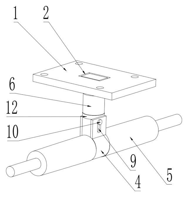
Sports & Recreation
Swivel-Pin Skateboard Truck with Rubber Sleeve
Skateboard truck with a turning center pin, a tilting axle clamp and a rubber sleeve that centers it.
Patent CN216777880U
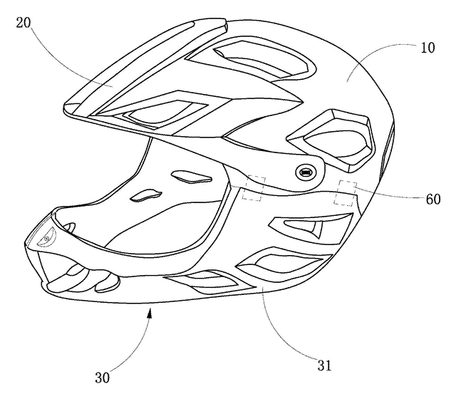
Sports & Recreation
Full-Face Bike Helmet with Magnetic Detachable Chin Bar
Full-face cycling helmet whose chin bar clips on and off with magnetic, latching side connectors.
Patent CN206630067U
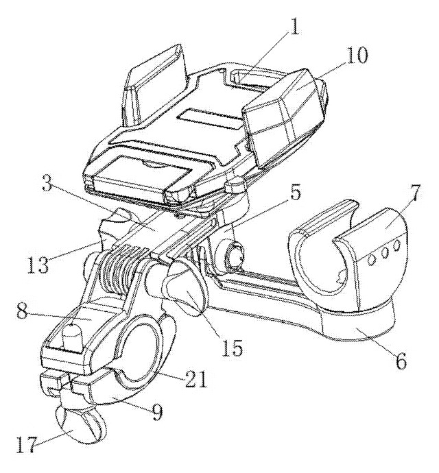
Sports & Recreation
Bike Phone Holder with Built-In Flashlight Clamp
Handlebar mount with a phone cradle on top and a flashlight clamp below, on one arm.
Patent CN206077485U
Browse by category
- Apparel & Accessories (46)
- Baby & Kids (28)
- Bags & Luggage (17)
- Bath & Personal Care (30)
- Car Accessories (25)
- Furniture, Bedding & Storage (23)
- Garden & Outdoor (32)
- Health & Wellness (14)
- Home, Kitchen & Cleaning (48)
- Lighting (23)
- Packaging & Containers (12)
- Pet Products (11)
- Phone & Camera Accessories (9)
- Retail Display (25)
- School, Office & Art (35)
- Sports & Recreation (45)
- Tools & Workshop (54)
- Toys & Games (22)
This page is based on the public patent document CN110812826B, assigned to Individual. IP2M is an independent manufacturing service and is not affiliated with, endorsed by or licensed by the patent owner. Images marked as concept renderings are illustrations, not photos of an existing product. Patent status information is provided for reference only and is not legal advice; confirm freedom to operate for your market before production. Full disclaimer.