
Patent CN110870604B
Updated November 6, 2026Seatbelt Buckle with Electromagnetic Lock and Laser Verification
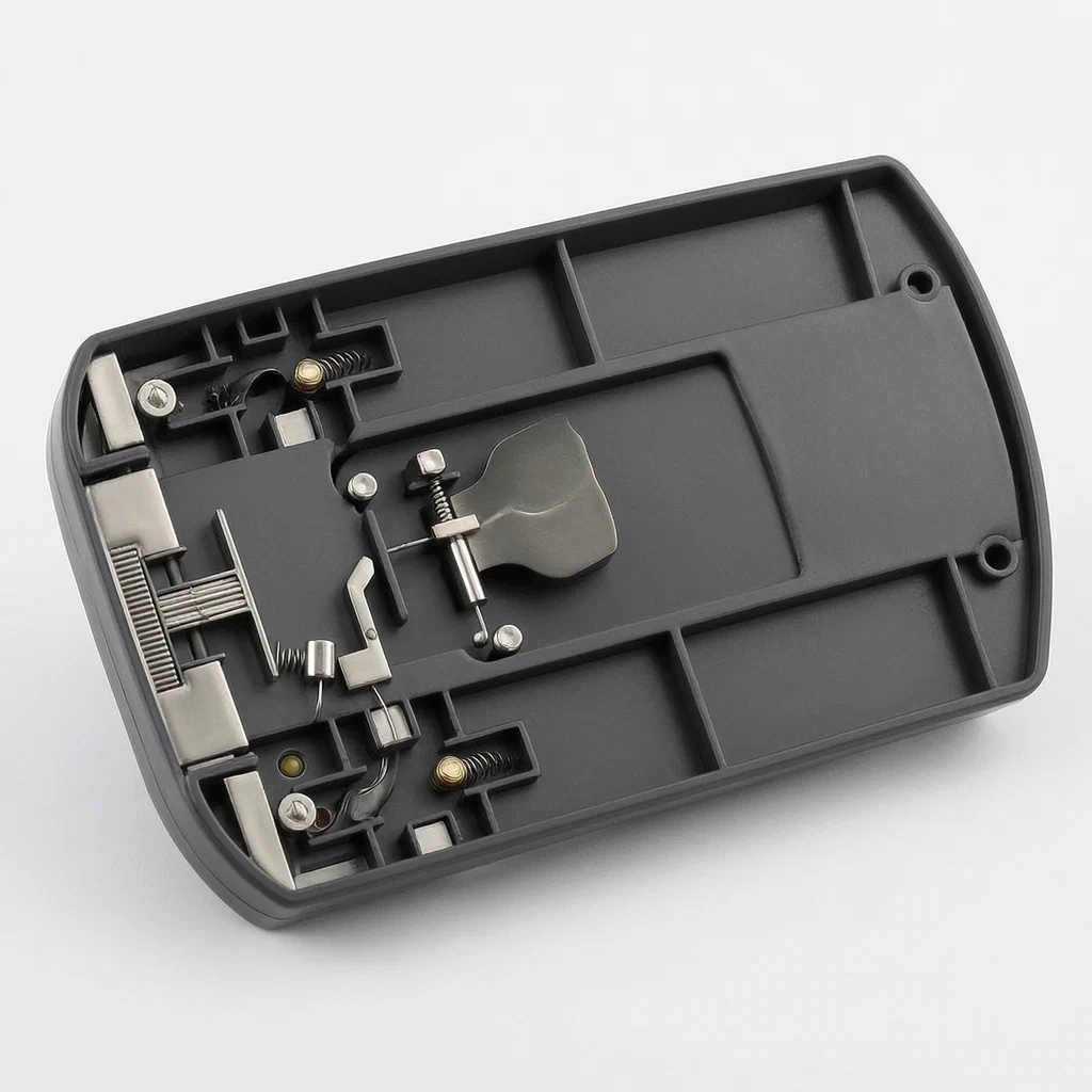
Standard seatbelt buckles rely on pure mechanics; if the tongue is not fully seated or vibrates loose, the system may fail silently. This design introduces active control. Inside the housing, an intelligent chip with an acceleration sensor judges the motion state. When conditions are met, it powers an electromagnet that attracts a rotating block. The block swings through a hole in the belt tongue, physically preventing withdrawal. To ensure this happens correctly, a laser ranging unit moves along a linear track. It first confirms the tongue is inserted by detecting its reflection, then confirms the block has rotated into position. This dual verification allows for precise monitoring of whether the belt is truly locked.
- China invention patent - in force
- No filings outside China
- Automotive safety components
- Electromagnetic actuation, laser ranging verification
Splat! What let you down?
🧲
Electromagnetic Locking
An electromagnet drives a rotating block through the belt tongue's hole to secure it.
🔦
Laser Verification
A moving laser unit confirms both tongue insertion and block rotation status.
📊
Motion Sensing
An onboard acceleration sensor helps judge when to engage the lock based on movement.
🛡️
Dual Confirmation
Separate signals for 'inserted' and 'locked' provide higher reliability than single switches.
Bring this product to market
- ✓ Patent review Patent family and legal status reviewed in the relevant jurisdictions.
- 2 Product brief · now How it works, uses and options written up
- 3 Prototype First samples for buyers to review
- 4 Pilot run Small first batch for launch customers
- 5 Volume production Repeat orders at scale
Buyer interest
– of 100 buyers needed to start prototyping
One click, no sign-up. Each vote is one real visitor, and products with the most interest go to prototyping first.
Build team: no members yet. Need a partner, co-funding or skills to build this? Join and we introduce the team once it forms.
Patent Rights & Team Participation
Before joining a development team, participants should ensure they have the necessary rights or authorization to participate in the project.
Participation is generally appropriate where:
- You own the relevant patent rights or have obtained permission or a license from the rights holder.
- The relevant patent rights have expired or have been legally invalidated in the jurisdictions where the planned activities will take place.
- The planned development, manufacturing, and commercialization activities have been independently assessed and do not infringe applicable patent rights in the relevant jurisdictions.
Important: Being located outside a country where a patent is protected does not automatically exempt you from patent infringement risks. Patent rights may apply based on where development, manufacturing, use, sale, or import activities take place.
IP2M does not grant any patent license or authorization through team participation. Joining a project does not provide permission to use, manufacture, or commercialize patented technology.
The problem
Traditional seatbelt buckles depend on mechanical spring tension and physical geometry to hold the tongue. In dynamic environments like off-road vehicles or heavy machinery, vibrations can cause micro-movements. If the tongue is not fully seated, or if the locking pawl wears down, the belt might release unexpectedly during a sudden stop or impact. Furthermore, standard buckles typically offer a binary signal: locked or unlocked. They cannot distinguish between a tongue that is loosely inserted but not fully engaged versus one that is securely locked. This lack of granular feedback limits the ability of advanced driver assistance systems (ADAS) to enforce proper usage.
The solution
The patent describes a buckle where the locking action is actively controlled and verified.
- An intelligent chip inside the housing includes an acceleration sensor and a processor. The processor analyzes motion data against set thresholds to determine the state of the buckle.
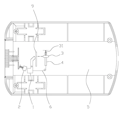
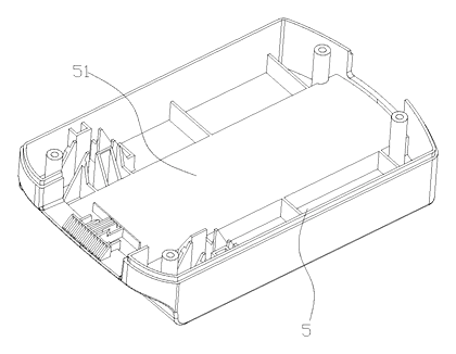
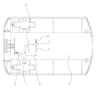
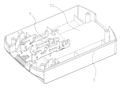
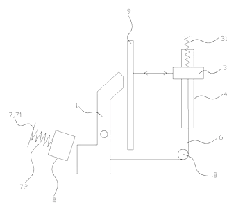
- The core mechanism is an electromagnetic fuse device. It consists of a rotating block (1) mounted elastically on the housing (5).
- An electromagnet (2) is positioned near the rotating block. When powered, it creates a magnetic field that attracts the end of the rotating block.
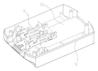
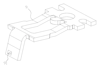
- As the block rotates, its opposite end penetrates a hole position (91) on the safety belt locking sheet (9) (the metal tongue). This physically blocks the tongue from being withdrawn.
- To verify this process, a laser ranging unit (3) emits a beam and receives reflections. It travels along a linear track (4).
- The laser unit is connected to the rotating block via a wire harness (6). As the block rotates, it pulls the wire, moving the laser unit along the track. A first spring (31) balances the pull force.
- The system generates two pieces of information: First, confirming the tongue is present; Second, confirming the rotating block has completed its travel to lock the tongue.
Who it is for
- Fleet Management Companies: Operators of commercial trucks or buses who need verifiable proof that drivers have actually locked their belts, not just inserted them.
- Automotive Suppliers: Tier 1 manufacturers looking to integrate smart safety features into next-generation restraint systems without replacing the entire belt architecture.
- Special Vehicle Manufacturers: Builders of construction equipment or military vehicles where high vibration requires positive locking mechanisms beyond simple springs.
- Telematics Providers: Companies developing insurance-based driving programs that require accurate, tamper-resistant data on seatbelt usage events.
How it works
The main parts
| No. | Part | What it does |
|---|---|---|
| 1 | Rotating Block | Pivots to insert a tab into the belt tongue’s hole. |
| 2 | Electromagnet | Generates magnetic force to drive the rotating block. |
| 3 | Laser Ranging Unit | Emits light to detect object presence and distance. |
| 4 | Linear Track | Guides the laser unit’s movement along a fixed path. |
| 5 | Housing | Encloses the electronics and mechanical parts. |
| 6 | Wire Harness | Connects the rotating block to the laser unit for power and motion transfer. |
| 7 | Elastic Support | Mounts the electromagnet with springs to absorb impact noise. |
| 8 | Roller Structure | Redirects the wire harness to prevent snagging. |
| 9 | Belt Tongue | The metal part of the seatbelt that inserts into the buckle. |
| 91 | Hole Position | The opening in the belt tongue where the block inserts. |
Operating Steps
- Insertion: The user inserts the belt tongue (9) into the buckle. The laser unit detects the reflective surface of the tongue, generating “First Information” that the belt is present.
- Activation: Based on the processor’s judgment (using acceleration data), the electromagnet (2) is powered on.
- Locking: The electromagnet attracts the rotating block (1). The block rotates around its pivot point.
- Verification: As the block rotates, it pulls the wire harness (6), sliding the laser unit (3) along the linear track (4). The laser reflects off the block itself, generating “Second Information” that the lock is engaged.
- Monitoring: The system continuously checks both signals. If the tongue is removed, the first signal changes. If the block fails to rotate, the second signal is absent.
Applications
Commercial Fleet Safety
Truck drivers often unbuckle briefly while driving or do not fully engage the latch. This buckle provides hard evidence of a “locked” state, helping companies comply with safety regulations and reduce liability in accidents.
High-Vibration Environments
In mining trucks or agricultural machinery, constant shaking can wear out traditional spring-loaded latches. The electromagnetic engagement ensures the belt stays secured even under rough terrain conditions, with the laser verifying the lock hasn’t disengaged.
Child Restraint Systems
For booster seats or child locks, accidental unfastening is a risk. The dual-sensor verification allows the vehicle’s computer to alert parents immediately if the belt is not positively locked, rather than just inserted.
Autonomous Vehicle Monitoring
Self-driving cars need to know passengers are safely restrained before engaging certain modes. The precise “locked” signal from the rotating block position offers a more reliable input for the AV’s decision logic than a simple mechanical switch.
Where it is less suitable
- Legacy Retrofitting: Vehicles without existing wiring for sensors may find the complexity of integrating power and data lines too high compared to simple mechanical buckles.
- Extreme Dust/Debris: Optical sensors like the laser ranging unit can be sensitive to opaque dust on the lens or reflectors, so dirty industrial settings would call for a cleaning routine.
Patent & Production
At a glance
| Patent number | CN110870604B (application CN202010057608) |
| Type | China invention patent (发明专利) - protects method and structure |
| Original title | Safety belt lock catch with electromagnetic safety function (一种具有电磁保险功能的安全带锁扣) |
| Patent owner | Jiangsu Zhikai Automobile Safety System Co ltd |
| Inventors | Jin Liya, Lü Jinlong |
| Filing date | 2020-01-19 |
| Grant date | 2020-04-14 |
| Status (China) | In force - valid until at most 2040-01-19, subject to payment of annual fees |
| Patent family | Public record shows Chinese filings only - no US, European, Japanese, PCT or other filings listed |
| Cited by | 0 later documents |
| Source | Google Patents (search for CN110870604B) |
What the claims cover, in plain language
Claim 1 - a seatbelt buckle with an electromagnetic safety function. It includes an intelligent chip with an acceleration sensor and processor. The processor controls an electromagnetic fuse device based on motion state. The device comprises a rotating block (1) elastically mounted on the housing (5), an electromagnet (2) that attracts the block when powered, causing the block to penetrate a hole (91) in the belt tongue (9). It also includes a laser ranging unit (3) on a linear track (4), connected to the block by a wire harness (6). A first spring (31) balances the harness pull.
Claim 2 - the electromagnet is mounted on an elastic support (7) consisting of a mounting plate (71) and a second spring (72) to buffer impact. Claim 3 - the coils of the second spring are arranged in abutment (touching) to stabilize force application. Claim 4 - the interface between the electromagnet and rotating block uses spherical or conical protrusions/grooves for alignment. Claim 5 - a roller structure (8) is placed midway on the wire harness to change its direction. Claim 6 - the linear track (4) is angled relative to the rotation plane of the block. Claim 7 - specifies the operational steps: power on -> laser emits -> tongue inserted (1st info) -> magnet activates -> block rotates -> laser shifts and reflects off block (2nd info) -> monitor both infos.
This is a simplified reading for orientation only. The legal scope is defined by the exact claim wording in the official Chinese document.
What this means for US production
This patent was filed in China and is currently in force. Making or selling this specific design in China would require the owner’s permission. However, the public record shows no US counterpart. Therefore, this patent does not restrict manufacturing or selling this design in the United States.
Two points to settle early:
- Other patents may exist. Automotive safety restraints are a heavily patented global field. Major suppliers like Autoliv, ZF, and Joyson Safety Systems hold extensive portfolios on electronic buckles, pretensioners, and occupancy detection. A freedom-to-operate (FTO) review is essential before tooling to ensure you do not infringe on US patents covering similar electromagnetic or optical sensing methods.
- Regulatory Certification. Unlike consumer goods, automotive components must meet strict safety standards (FMVSS in the US). Even if the patent doesn’t block you, getting certification for a novel locking mechanism is a significant engineering hurdle.
Customization and manufacturing
What can be customized
| Area | Options |
|---|---|
| Housing Material | Engineering plastics (PA66+GF30) or metal alloys for heat dissipation. |
| Electromagnet Specs | Coil voltage, holding force, and response time tailored to vehicle electrical systems (12V/24V). |
| Sensor Integration | Output format for CAN bus or LIN network communication. |
| Track Geometry | Angle and length of the linear track adjusted for available space in the console. |
| Connector Type | Wire harness connectors compatible with OEM harnesses (e.g., Molex, TE Connectivity). |
Things to plan for (US market)
- FMVSS 209 / SAE J442: Dynamic strength requirements for seatbelt assemblies. The buckle must withstand high loads without failure.
- ISO 26262: Functional safety for road vehicles. Since this involves a safety-critical system (locking), the software and hardware must meet ASIL (Automotive Safety Integrity Level) ratings.
- EMC Compliance: FCC Part 15 (unintentional radiators) and CISPR 25 for electromagnetic compatibility, ensuring the electromagnet and laser don’t interfere with other car electronics.
How a project runs
- Concept & FTO - Verify design freedom and define electrical interfaces.
- Simulation - Model magnetic forces, spring rates, and laser reflection paths.
- Prototype - Build functional units with machined housings and off-the-shelf sensors.
- Validation - Test cycle life, temperature extremes, vibration, and EMC.
- Tooling & PPAP - Create injection molds and submit Production Part Approval Process documentation to the automaker.
Quantities & timeline
Development cycles for automotive safety components are long due to testing requirements. Tooling for the housing and precision parts takes several months. Validation tests (vibration, thermal cycling) add further time. Send us your target vehicle platform, electrical specs, and quantity estimates and we will reply with options.
Production notes
Tooling and process
Likely, the housing requires multi-cavity injection molding for high-volume consistency. The rotating block and electromagnet assembly may involve PCB assembly and precise mechanical fitting. TPU injection molding could be used for protective seals or flexible mounts.
Cost drivers
Cost depends on the grade of the electromagnet materials and the precision of the laser module. Hardware corrosion resistance adds to material costs. Spring fatigue and rate consistency are critical quality factors that drive inspection costs. Wall thickness and joint design affect mold complexity.
Prototyping path
We would likely start with 3D-printed or cast components for fit grading. A sewn first sample isn’t applicable here, but a wired prototype is essential. Wear trials should simulate thousands of insertions. Fit grading ensures the laser aligns correctly across different tongue sizes.
What we would change before tooling
Before finalizing tools, we would likely adjust the roller structure (8) to minimize wire routing strain. We would also test spring fatigue rates to ensure the elastic support (7) doesn’t degrade over time. Magnet grade and retention should be verified under high-vibration conditions.
Common failure points
Wire routing and strain relief are potential weak spots given the moving parts. Spring fatigue could lead to inconsistent locking force. Hardware corrosion in the electromagnet contacts might cause intermittent failures. Sole delamination isn’t relevant, but adhesive bonding integrity for sensor lenses is a concern. Size deviation in the hole position (91) could prevent the block from inserting.
Patent drawings
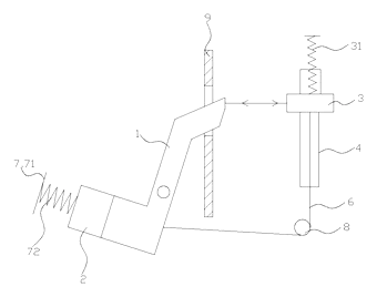
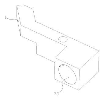
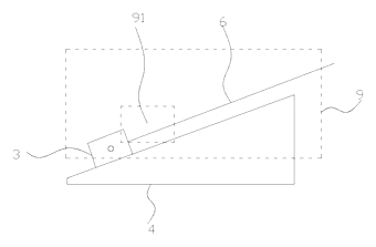
Drawings reproduced from the public patent document for reference.
Frequently asked questions
How does the lock work differently from a standard buckle?
A standard buckle uses a spring-loaded pawl that snaps into the tongue. This design uses an electromagnet to pull a rotating block. The block swings through a hole in the tongue, physically blocking it. This is an active lock, not just a passive snap-fit.
Why use a laser sensor?
The laser provides two distinct confirmations. First, it detects the metal tongue is present. Second, as the rotating block moves, the laser tracks its position. This confirms the block has fully rotated into the locking position, ensuring the belt is actually secured, not just inserted.
Does it require special wiring?
Yes. Unlike a mechanical buckle, this unit needs power for the electromagnet and the laser sensor. It also needs data lines to send the “locked” status to the vehicle’s computer. Integration requires connecting to the car’s CAN bus or similar network.
Is it safe if the power fails?
The patent describes the system relying on the processor to control the magnet. In a typical safety design, fail-safe mechanisms (like strong springs or gravity) would be engineered to keep the belt locked or allow emergency release depending on the specific implementation strategy, which must be validated for FMVSS compliance.
Can it be retrofitted into any car?
Not easily. The housing dimensions, electrical connections, and software integration are specific to the vehicle platform. It is best suited for new vehicle designs or specialized fleet modifications where custom consoles can be built.
What materials are used?
The housing is typically engineering plastic or metal. The rotating block and electromagnet use magnetic materials and steel. The laser unit is a solid-state optical component. All parts must withstand automotive temperature ranges (-40°C to +85°C).
Can this design be made and sold in the US?
The patent is in force in China, but the public record shows no US counterpart. Therefore, it does not restrict manufacturing or selling this design in the US. However, automotive safety components are heavily patented globally. We strongly recommend a freedom-to-operate (FTO) review to check for US patents held by major suppliers like Autoliv or ZF before proceeding.
Are you affiliated with the patent owner?
No. IP2M is an independent design and manufacturing service working from the public patent document.
Request a quote
Click Request a Quote below to see our email address - copy it, or open your email app with a ready-made message. Please mention patent CN110870604B in the subject.
Helpful details to include:
- Your company and channel (automotive supplier, fleet operator, specialty vehicle manufacturer)
- Vehicle platform and electrical system voltage (12V/24V)
- Integration requirements (CAN bus protocol, connector types)
- Target volume and timeline
- Specific challenges (space constraints, vibration levels)
You can also reach us at (332) 203-9997.
Page editor: Emily Zhang, Product Editor · IP2M
Last updated November 6, 2026. If something on this page looks wrong, email [email protected] and we will check it against the patent.
Interested in building this?
Tell us your target market, quantity and timeline. We reply with options for prototyping, small-batch runs or volume production.
Send your inquiry to
Please put CN110870604B in the subject line and tell us your company, country, estimated quantity and timeline.
Prefer to talk? Call (332) 203-9997.
More product-ready patents
All Apparel & Accessories patents →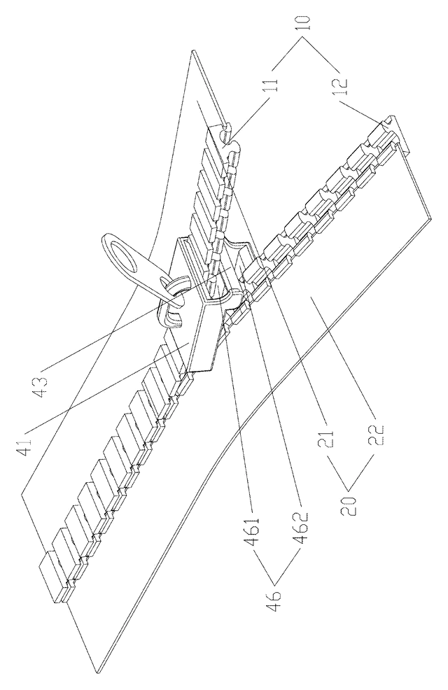
Apparel & Accessories
Stacked Zipper with Teeth That Mesh Top-to-Bottom
Zipper whose two identical tooth rows mesh on top of each other, closed by a simplified slider.
Patent CN205795062U
Apparel & Accessories
Impact-Resistant Glove with a 3D-Printed Lattice Layer
Work glove with a 3D-printed lattice impact layer, TPU knuckle guards and a light mounting area.
Patent CN213785583U
Apparel & Accessories
Massage Insole with Spring-Back Silicone Nubs and a Removable Top Layer
Layered insole: silicone nubs rise through a removable perforated top sheet and sink under each step.
Patent CN208286505U
Apparel & Accessories
Heel-Less Carbon Plate Running Shoe Sole for Forefoot Strikers
Running sole for forefoot strikers: no ground-touching heel, winged carbon plate between two midsoles.
Patent CN216723354U
Apparel & Accessories
Waterproof Magnetic Zipper Stop That Snaps the Two Halves Together
Separating-zipper stop with sealed magnets: pin and box snap together one-handed, safe in rain and wash.
Patent CN215075936U
Apparel & Accessories
Left-Right Specific Soccer Socks: Grip for the Plant Foot, Touch Pads for the Kicking Foot
Soccer socks knitted as a left-right pair: grip zones for the plant foot, pads for the kicking foot.
Patent CN212728807U
Browse by category
- Apparel & Accessories (45)
- Baby & Kids (28)
- Bags & Luggage (16)
- Bath & Personal Care (30)
- Car Accessories (24)
- Furniture, Bedding & Storage (23)
- Garden & Outdoor (31)
- Health & Wellness (13)
- Home, Kitchen & Cleaning (48)
- Lighting (22)
- Packaging & Containers (12)
- Pet Products (11)
- Phone & Camera Accessories (9)
- Retail Display (24)
- School, Office & Art (34)
- Sports & Recreation (44)
- Tools & Workshop (53)
- Toys & Games (22)
This page is based on the public patent document CN110870604B, assigned to Jiangsu Zhikai Automobile Safety System Co ltd. IP2M is an independent manufacturing service and is not affiliated with, endorsed by or licensed by the patent owner. Images marked as concept renderings are illustrations, not photos of an existing product. Patent status information is provided for reference only and is not legal advice; confirm freedom to operate for your market before production. Full disclaimer.