
Patent CN111202310B
Updated October 29, 2026Mechanical Quick-Release Rope and Belt Buckle with Flip Lock
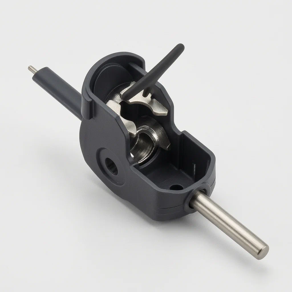
Standard cord locks rely on spring tension or friction, which can slip under load or require two hands to release. This mechanical buckle replaces springs with a rigid flip action. A handle pivots on a rotating shaft inside a base cylinder. When closed, an elastic Ω-shaped clasp on the flip mechanism snaps over the cylinder to hold the rope in place. When the handle is flipped back 90 degrees, the clasp releases, and a tapered hole in the shaft aligns with the base hole so the cord slides through without friction. The geometry of the holes—round, elliptical, or polygonal—is matched to the cord profile, and a side operation window lets the user guide the material during threading.
- China invention patent - in force
- No filings outside China
- Fasteners & Accessories
- Mechanical flip-lock, no springs required
Splat! What let you down?
🔓
Flip-to-release action
Pulling the handle 90 degrees separates the elastic Ω-clasp from the cylinder, opening the path for the rope.
⚙️
Rotating shaft alignment
A fourth through hole in the shaft turns with the handle to align with the base hole for free cord travel.
📐
Tapered entry hole
The shaft hole is wider at the entrance than the exit, guiding flat belts or round ropes smoothly into the passage.
👁️
Side operation window
An operation hole on the base wall allows visual inspection and finger guidance while threading the cord.
Bring this product to market
- ✓ Patent vetted China-only family and legal status checked
- 2 Product brief · now How it works, uses and options written up
- 3 Prototype First samples for buyers to review
- 4 Pilot run Small first batch for launch customers
- 5 Volume production Repeat orders at scale
Buyer interest
– of 100 buyers needed to start prototyping
One click, no sign-up. Each vote is one real visitor, and products with the most interest go to prototyping first.
Build team: no members yet. Need a partner, co-funding or skills to build this? Join and we introduce the team once it forms.
The problem
Rope and belt fasteners used on bags, apparel, and outdoor gear typically depend on internal springs or simple friction wedges to grip the cord. Over time, springs lose tension, and friction surfaces wear smooth, causing the lock to slip when the load increases. Releasing these mechanisms often requires pinching small buttons or pulling against heavy spring resistance, which is difficult with gloves or when operating quickly. Additionally, many cord locks are designed only for round cords; when used with flat webbing or belts, the mismatch between the round internal channel and the flat material creates uneven pressure points, leading to premature wear on the fabric and unreliable holding force. Manufacturers seeking a durable, tool-free adjustment method need a locking system that does not rely on consumable spring parts and accommodates different cord profiles.
The solution
This mechanical quick-release buckle eliminates internal springs by using a rigid flip mechanism and an elastic clasp to secure the cord.
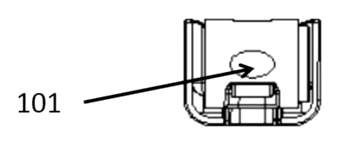
- A base (1) contains a longitudinal cylinder (11) with a first through hole (101) running its length. A second through hole (102) intersects it perpendicularly at the same horizontal center line.
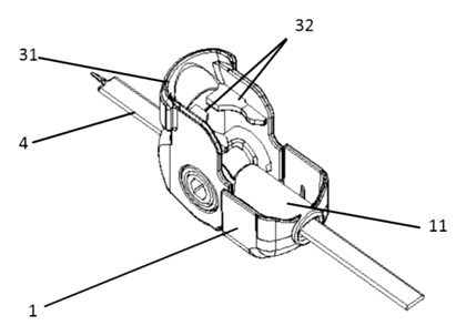
- A rotating shaft (2) sits inside the second through hole. Its middle section has a radial fourth through hole (22), and its outer wall features a positioning boss (23).
- A flip mechanism (3) connects to the base via the rotating shaft. It includes a handle (31) and an elastic Ω-shaped buckle (32) on its inner wall. The mechanism’s side walls sit inside the base’s side walls. One wall has a circular hole; the opposite wall has a hole with a groove that engages the positioning boss, so flipping the mechanism turns the shaft.
- The end of the second through hole where the boss sits has a quarter-arc notch, allowing the boss to rotate exactly 90 degrees.
- To lock, the handle is pulled down. The flip mechanism buckles against the base, and the elastic Ω-shaped buckle snaps over the longitudinal cylinder, clamping the rope.
- To release, the handle is flipped in the opposite direction until the mechanism stands at 90 degrees to the cylinder. The Ω-shaped buckle separates, and the first through hole aligns with the fourth through hole, creating a continuous passage for the rope.
Who it is for
- Bag and luggage brands looking for a durable, spring-free cord lock for drawstring closures on backpacks, duffels, or laundry bags.
- Apparel manufacturers needing a reliable toggle for adjustable hems, hood cords, or waistbands on jackets and workwear.
- Outdoor and sporting goods makers requiring a glove-friendly release mechanism for tent guylines, gear tarps, or equipment covers.
- Wholesalers of garment hardware adding a mechanical alternative to standard plastic spring-loaded cord stops.
How it works
The main parts
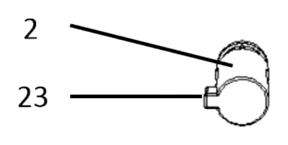
| No. | Part | What it does |
|---|---|---|
| 1 | Base | Houses the longitudinal cylinder and intersecting holes. |
| 11 | Longitudinal cylinder | The main body the rope passes through and the clasp grips. |
| 101 | First through hole | The primary passage for the rope along the cylinder. |
| 102 | Second through hole | Perpendicular hole housing the rotating shaft. |
| 2 | Rotating shaft | Pivots inside the second hole to align or block the rope path. |
| 22 | Fourth through hole | Radial hole in the shaft; tapers from entrance to exit. |
| 23 | Positioning boss | Protrusion on the shaft that engages the flip mechanism’s groove. |
| 3 | Flip mechanism | Pivoting assembly carrying the handle and locking clasp. |
| 31 | Handle | Lever pulled by the user to lock or release the buckle. |
| 32 | Elastic Ω-shaped buckle | Clasp that snaps over the cylinder to lock the rope. |
Operating steps
- Thread the rope through the aligned first and fourth through holes while the handle is in the open (90-degree) position. The side operation hole allows visual confirmation and finger adjustment.
- Pull the handle down toward the base. The groove on the flip mechanism turns the rotating shaft via the positioning boss.
- Lock the cord. As the mechanism closes, the elastic Ω-shaped buckle snaps over the longitudinal cylinder, pinching the rope securely.
- Release the cord. Flip the handle back up 90 degrees. The boss travels within the quarter-arc notch, the Ω-shaped buckle clears the cylinder, and the shaft rotates until the fourth through hole aligns perfectly with the first through hole, freeing the rope.
Applications
Backpacks and drawstring bags
Bag manufacturers use this buckle to secure the main compartment closure on drawstring backpacks or stuff sacks. The rigid flip handle is easier to operate than small plastic toggles, especially when the bag is fully loaded. The tapered entry hole accommodates both round paracord and flat webbing without fraying the material.
Outerwear and workwear hems
Apparel makers apply the buckle to adjustable waistbands or hood cords on jackets and coveralls. Because there is no internal spring to rust or fatigue, the fastener withstands repeated washing cycles. The low-profile handle lies flat against the garment when locked.
Tent and tarp guylines
Outdoor gear companies use the buckle to tension and release tent guylines or tarp tie-outs. Campers wearing gloves can flip the large handle easily compared to squeezing a traditional cord lock. The mechanical clamping holds steady under wind loads without creeping.
Pet leashes and harnesses
Pet product brands integrate the buckle into adjustable-length leashes or harness straps. The quick-release action allows the owner to adjust the strap length rapidly during walks. The positive snap of the Ω-shaped clasp provides audible feedback that the leash is secured.
Where it is less suitable
- Heavy-duty load-bearing climbing gear - life-safety climbing equipment requires certified load-rated carabiners and belay devices, not general-purpose cord buckles.
- Ultra-thin decorative cords - very fine threads may not provide enough friction surface for the cylinder clasp to grip effectively.
- Fully concealed inline applications - the handle extends outward from the base when operated, making it unsuitable for completely hidden, flush-mounted routing channels.
Frequently asked questions
How does the buckle lock and release the rope?
When the handle is pulled down, the flip mechanism buckles against the base, and the elastic Ω-shaped clasp snaps over the longitudinal cylinder to pinch the rope. Flipping the handle back 90 degrees lifts the clasp off the cylinder and rotates the internal shaft so its hole aligns with the base hole, letting the rope slide freely.
Does it work with flat webbing or only round cords?
The patent describes the through holes as being circular, elliptical, polygonal, or any combination of two of these shapes. For flat belts or webbing, an elliptical hole profile is specified in the document to prevent obstacles during passage. The exact dimensions are set in design / confirmed on prototypes based on your material thickness.
Are there springs inside that can break?
No. The mechanism relies entirely on the elasticity of the Ω-shaped clasp and the mechanical rotation of the shaft. There are no coil springs or compression springs mentioned in the patent, which reduces the number of small parts that can fatigue or fail.
What is the purpose of the tapered hole in the shaft?
The fourth through hole in the rotating shaft is conical, meaning the cross-sectional area at the rope entrance is larger than at the exit. The patent states this gradual decrease from entrance to exit improves the efficiency of passing the rope or belt through the buckle.
Can I see the rope while I am threading it?
Yes. The patent specifies an operation hole opened on the side wall of the second through hole. This window allows the user to look down from the handle direction to visually check the rope and use fingers to guide or adjust it during threading.
How is the rotation limited to exactly 90 degrees?
A positioning boss on the outer wall of the rotating shaft fits into a groove on the flip mechanism’s side wall. The base’s second through hole has a notch with a quarter-arc length at the end where the boss sits. This physical boundary restricts the shaft’s rotation to 90 degrees between the locked and open positions.
Can this design be made and sold in the US?
The patent was filed only in China and has no US counterpart, so it does not restrict making or selling the design in the United States. However, it remains in force in China until at most 2040-03-25 (if annual fees are paid), meaning production in China requires the owner’s permission. Other US patents on cord locks may exist, so a freedom-to-operate review is recommended before volume production.
Are you affiliated with the patent owner?
No. IP2M is an independent design and manufacturing service working from the public patent document.
Request a quote
Click Request a Quote below to see our email address - copy it, or open your email app with a ready-made message. Please mention patent CN111202310B in the subject.
Helpful details to include:
- Your company and channel (bag brand, apparel maker, outdoor gear manufacturer, hardware wholesaler)
- Cord or webbing type (round diameter or flat width/thickness)
- Preferred materials for the base, handle, and elastic clasp
- Hole profile requirement (circular, elliptical, or custom)
- Estimated quantity and target price
- Timeline - when you would like samples and the first shipment
You can also reach us at (332) 203-9997.
Explore this product
Interested in building this?
Tell us your target market, quantity and timeline. We reply with options for prototyping, small-batch runs or volume production.
Send your inquiry to
Please put CN111202310B in the subject line and tell us your company, country, estimated quantity and timeline.
Prefer to talk? Call (332) 203-9997.
More product-ready patents
All Apparel & Accessories patents →
Apparel & Accessories
Stacked Zipper with Teeth That Mesh Top-to-Bottom
Zipper whose two identical tooth rows mesh on top of each other, closed by a simplified slider.
Patent CN205795062U
Apparel & Accessories
Impact-Resistant Glove with a 3D-Printed Lattice Layer
Work glove with a 3D-printed lattice impact layer, TPU knuckle guards and a light mounting area.
Patent CN213785583U
Apparel & Accessories
Massage Insole with Spring-Back Silicone Nubs and a Removable Top Layer
Layered insole: silicone nubs rise through a removable perforated top sheet and sink under each step.
Patent CN208286505U
Apparel & Accessories
Heel-Less Carbon Plate Running Shoe Sole for Forefoot Strikers
Running sole for forefoot strikers: no ground-touching heel, winged carbon plate between two midsoles.
Patent CN216723354U
Apparel & Accessories
Waterproof Magnetic Zipper Stop That Snaps the Two Halves Together
Separating-zipper stop with sealed magnets: pin and box snap together one-handed, safe in rain and wash.
Patent CN215075936U
Apparel & Accessories
Left-Right Specific Soccer Socks: Grip for the Plant Foot, Touch Pads for the Kicking Foot
Soccer socks knitted as a left-right pair: grip zones for the plant foot, pads for the kicking foot.
Patent CN212728807U
Browse by category
- Apparel & Accessories (22)
- Baby & Kids (16)
- Bags & Luggage (9)
- Bath & Personal Care (16)
- Car Accessories (10)
- Furniture, Bedding & Storage (12)
- Garden & Outdoor (18)
- Health & Wellness (8)
- Home, Kitchen & Cleaning (24)
- Lighting (12)
- Packaging & Containers (6)
- Pet Products (6)
- Phone & Camera Accessories (4)
- Retail Display (13)
- School, Office & Art (19)
- Sports & Recreation (25)
- Tools & Workshop (27)
- Toys & Games (12)
This page is based on the public patent document CN111202310B, assigned to Individual. IP2M is an independent manufacturing service and is not affiliated with, endorsed by or licensed by the patent owner. Images marked as concept renderings are illustrations, not photos of an existing product. Patent status information is provided for reference only and is not legal advice; confirm freedom to operate for your market before production. Full disclaimer.