At a glance
| Patent number | CN111202310B (application CN202010219434) |
| Type | China invention patent (发明专利) - protects product shape, structure and method |
| Original title | A mechanical rope belt quick elastic buckle (一种机械式绳带快速松紧扣) |
| Patent owner | Individual |
| Inventors | Feng Feihua |
| Filing date | 2020-03-25 |
| Grant date | 2025-03-07 |
| Status (China) | In force in China until at most 2040-03-25 (if annual fees are paid) |
| Patent family | Chinese filings only - no US, European, Japanese, PCT or other filings listed |
| Cited by | 0 later documents |
| Source | Google Patents (search for CN111202310B) |
What the claims cover, in plain language
Claim 1 - a mechanical rope quick release buckle comprising a base (1), a rotating shaft (2) and a flip mechanism (3). The base includes a longitudinal cylinder (11) with a first through hole (101) running through it, and a second through hole (102) perpendicular to the first, with both center lines at the same horizontal height. The rotating shaft sits inside the second through hole and has a radial fourth through hole (22) in its middle and a positioning boss (23) on its outer wall. The flip mechanism connects rotatably to the base via the shaft and includes a handle (31) and an elastic Ω-shaped buckle (32). The flip mechanism has holes on its side walls—one circular, one with a groove engaging the positioning boss so flipping the mechanism turns the shaft. A quarter-arc notch in the second through hole allows the boss to rotate. The mechanism’s side walls sit inside the base’s side walls. Pulling the handle snaps the Ω-shaped buckle over the longitudinal cylinder to lock; pulling it in the opposite direction to 90 degrees separates the buckle, aligning the first and fourth through holes so the rope passes freely. The holes can be round, elliptical, polygonal, or combinations. The fourth through hole is tapered, with the entrance cross-section larger than the exit. An operation hole is provided on the side wall of the second through hole.
This is a simplified reading for orientation only. The legal scope is defined by the exact claim wording in the official Chinese document.
What this means for US production
This patent was filed only in China and is currently in force. There is no US or other foreign counterpart. However, because it is active in China, making or selling this specific buckle design in China needs the owner’s permission.
Two points to settle early:
- Other patents may exist. Cord locks, toggle fasteners, and quick-release buckles for apparel and bags are covered by numerous existing patents held by major global hardware and outdoor brands. A freedom-to-operate (FTO) review focusing on the flip-lock mechanism and tapered shaft hole is recommended before launching production for the US market.
- Material selection for the elastic clasp. The patent specifies an “elastic Ω-shaped buckle” but does not dictate the material. The choice of polymer or metal for this clasp determines the cycle life and UV resistance, which must be validated for the intended application.
Customization and manufacturing
What can be customized
| Area | Options |
|---|---|
| Hole profile | Circular, elliptical, polygonal, or mixed shapes to match round cords or flat webbing |
| Dimensions | Overall size scaled to accommodate cord diameters to be confirmed in design |
| Materials | Base and handle in POM, nylon, or zinc alloy; elastic clasp in spring steel or flexible polymer |
| Finish | Matte, polished, painted, or plated surfaces depending on material choice |
| Taper ratio | The difference between the entrance and exit cross-sections of the fourth through hole set in design |
| Mounting | Integration loops or flanges added to the base for sewing or riveting onto bags and garments |
Things to plan for (US market)
- CPSC 16 CFR 1501 - small parts regulation; if the buckle is used on children’s products (e.g., kids’ bags or apparel), it must not present a choking hazard.
- CPSIA Section 101 - lead content limits for substrates and surface coatings on products designed primarily for children 12 and under.
- California Proposition 65 - materials and plating finishes must be screened for listed chemicals if sold in California.
How a project runs
- Inquiry - target application, cord type (round or flat), dimensions, material preferences and quantity.
- Design - CAD modeling of the base, shaft taper, hole profiles and the elastic Ω-clasp geometry.
- Prototype - 3D printing or CNC machining of samples to verify the 90-degree flip action, clasp snap-fit and cord sliding friction.
- Pilot run - mold fabrication followed by a short injection-molding or die-casting run for cycle testing and fit checks with actual cords.
- Production - full-scale molding, finishing, assembly of the shaft into the base, and packaging.
Quantities & timeline
The base, flip mechanism, and rotating shaft each require dedicated injection molds or die-casting dies depending on the chosen material. The elastic Ω-shaped buckle may need a separate stamping die if made from metal, or a specific mold insert if molded from polymer. Tooling complexity scales with the selected hole profile (tapered elliptical holes require precise core pins). Cycle-life testing of the clasp engagement and UV exposure testing for outdoor applications add to the validation phase. Send us your target application, cord dimensions, material preference, estimated quantity and timeline and we will reply with options.
Patent drawings
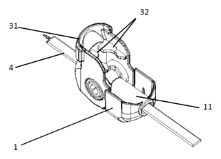
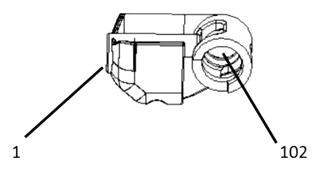
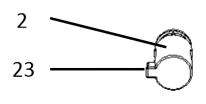
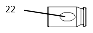
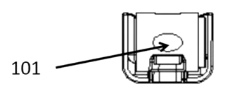
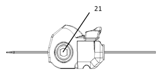
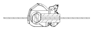
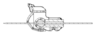
Drawings reproduced from the public patent document for reference.