
Patent CN111358122B
Updated November 5, 2026Hall-Effect Switched Seat Belt Buckle Assembly
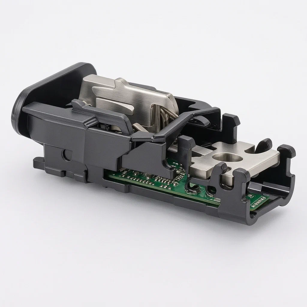
Traditional seat belt buckles rely on purely mechanical switches or complex internal wiring that can fail due to vibration and wear. This design separates the electronics from the locking mechanism. A magnet attached to the moving ejector part travels alongside a stationary Hall-effect sensor on a dedicated circuit board. Because the sensor board is fixed to the outer shell rather than the moving parts, it avoids damage from the latch's reciprocating motion. This ensures stable signal transmission for seat occupancy detection while allowing the electronic module to be serviced without disassembling the entire lock core.
- China invention patent - active
- No filings outside China
- Automotive safety components
- Hall-effect sensing, separate PCBA mounting
Splat! What let you down?
🔒
Magnet-driven sensing
The latch tongue moves a magnet assembly directly opposite a Hall sensor to detect lock status.
🔌
Isolated PCBA
The circuit board is fixed to the lower shell, separated from the moving lock core to prevent damage.
🛠️
Serviceable design
Electronic faults can be addressed by removing the lower shell, without disassembling the lock mechanism.
📡
Vehicle integration
The Hall switch connects to the car system via wire to report worn/unworn states accurately.
Bring this product to market
- ✓ Patent review Patent family and legal status reviewed in the relevant jurisdictions.
- 2 Product brief · now How it works, uses and options written up
- 3 Prototype First samples for buyers to review
- 4 Pilot run Small first batch for launch customers
- 5 Volume production Repeat orders at scale
Buyer interest
– of 100 buyers needed to start prototyping
One click, no sign-up. Each vote is one real visitor, and products with the most interest go to prototyping first.
Build team: no members yet. Need a partner, co-funding or skills to build this? Join and we introduce the team once it forms.
Patent Rights & Team Participation
Before joining a development team, participants should ensure they have the necessary rights or authorization to participate in the project.
Participation is generally appropriate where:
- You own the relevant patent rights or have obtained permission or a license from the rights holder.
- The relevant patent rights have expired or have been legally invalidated in the jurisdictions where the planned activities will take place.
- The planned development, manufacturing, and commercialization activities have been independently assessed and do not infringe applicable patent rights in the relevant jurisdictions.
Important: Being located outside a country where a patent is protected does not automatically exempt you from patent infringement risks. Patent rights may apply based on where development, manufacturing, use, sale, or import activities take place.
IP2M does not grant any patent license or authorization through team participation. Joining a project does not provide permission to use, manufacture, or commercialize patented technology.
The problem
In many automotive safety systems, determining whether a seat belt is fastened requires reliable electrical feedback. Traditional designs often integrate switches directly into the moving mechanical parts of the buckle. This creates two issues: first, the constant reciprocating motion of the latch tongue and release mechanisms can fatigue or break fragile electrical connections and sensors over time. Second, if the electronic component fails, repairing it usually requires disassembling the entire lock core assembly, which is labor-intensive and risks compromising the mechanical integrity of the safety device. There is a need for a buckle structure where the sensing element remains stable and accessible, independent of the high-stress mechanical locking action.
The solution
- The buckle consists of a lock core assembly (1) enclosed by an upper cover shell (2) and a lower cover shell (3). These shells snap together to form the outer housing.
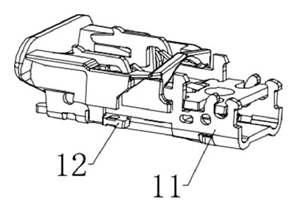
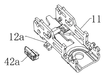
- Inside the lock core, a slot-shaped seat (11) houses the locking function parts. An ejector part (12) extends through this seat and moves back and forth as the latch tongue (6) is inserted or removed.
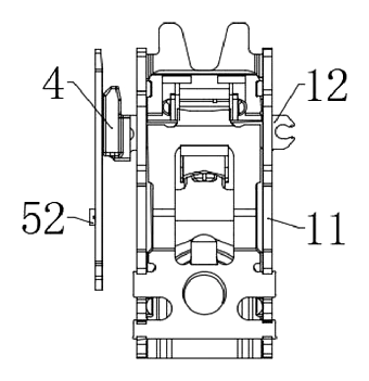
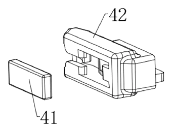
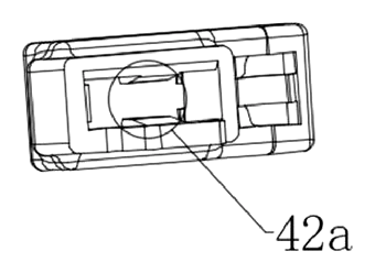
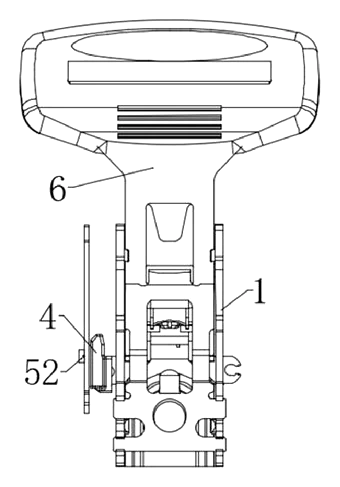
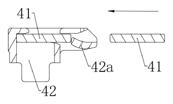
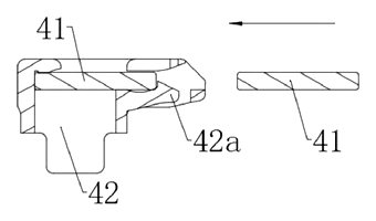
- A magnet assembly (4) is attached to the ejector part. It includes a magnet bracket (42) holding a magnet (41), secured by an elastic piece. As the latch tongue engages, it drives the ejector, causing the magnet assembly to move linearly.
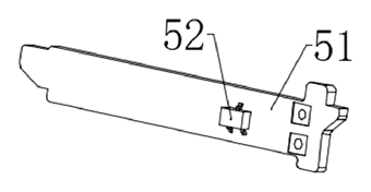
- A switch assembly (5) is installed within the lower cover shell (3), not inside the lock core. This assembly contains a PCBA (51) with a Hall-effect switch chip (52).
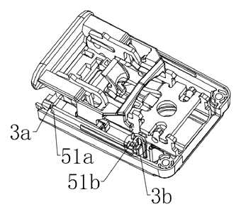
- The PCBA is oriented so its length matches the movement path of the magnet assembly. One end is guided by a guide column (51a) into a square hole (3a) in the shell, and the other end snaps into a fixing structure (51b).
- When the belt is locked, the magnet assembly moves to a position directly opposite the Hall sensor, changing the output signal sent to the vehicle system. When unlocked, the magnet moves away, returning the signal to the idle state.
Who it is for
- Automotive tier-1 suppliers integrating smart seat monitoring systems into existing buckle platforms.
- Electric vehicle manufacturers requiring precise passenger presence detection for autonomous driving features.
- Aftermarket safety retrofit companies needing serviceable electronic modules for fleet vehicles.
- Industrial machinery makers adapting seat belt interlocks for construction equipment operator safety.
How it works
The main parts
| No. | Part | What it does |
|---|---|---|
| 1 | Lock Core Assembly | Houses the mechanical locking mechanism. |
| 2, 3 | Upper/Lower Cover Shells | Enclose the assembly; lower shell holds the electronics. |
| 4, 41, 42 | Magnet Assembly | Magnet (41) in bracket (42); moves with the latch. |
| 5, 51, 52 | Switch Assembly | PCBA (51) with Hall chip (52); fixed to lower shell. |
| 6 | Latch Tongue | The metal plate from the belt that inserts into the buckle. |
| 11, 12 | Slot Seat & Ejector | Guides the latch and drives the magnet assembly. |
| 51a, 3a | Guide Column & Hole | Aligns one end of the PCBA. |
| 51b, 3b | Snap-in Structure | Secures the other end of the PCBA. |
Operating steps
- Insertion: The latch tongue (6) enters the lock core assembly (1).
- Mechanical Action: The tongue pushes the ejector part (12), which slides within the slot seat (11).
- Magnet Movement: The ejector carries the magnet assembly (4) along a linear path toward the lower shell.
- Sensing: At the locked position, the magnet (41) aligns directly opposite the Hall switch (52) on the stationary PCBA (51).
- Signal Transmission: The Hall chip detects the magnetic field and sends a specific current signal via wires to the vehicle’s control unit.
- Release: Pressing the release button reverses the ejector, moving the magnet away from the sensor, resetting the signal to indicate an unbuckled state.
Applications
Passenger Vehicle Interiors
Modern cars use seat belt status to trigger airbag deployment logic and dashboard warnings. This buckle provides a reliable signal without embedding fragile wires in the moving latch mechanism, reducing false alarms caused by vibration-induced contact failures.
Fleet Management Systems
Commercial trucks and buses monitor driver compliance. The separate PCBA allows fleet technicians to replace faulty sensor boards quickly by opening the lower shell, minimizing vehicle downtime compared to replacing the entire buckle assembly.
Autonomous Driving Integration
Self-driving vehicles require confirmation that passengers are restrained before engaging certain modes. The precise Hall-effect detection offers a clear digital state change (locked vs. unlocked) that integrates easily with advanced driver-assistance systems (ADAS).
Heavy Machinery Cabins
Construction equipment operators must remain seated during operation. This robust design withstands cabin vibrations better than mechanical micro-switches, providing consistent data to the machine’s safety interlock system.
Where it is less suitable
- Ultra-low-cost legacy replacements - Existing simple mechanical buckles may not justify the cost of adding a PCBA and wiring harness.
- Non-electronic retrofits - Vehicles without existing seat belt warning circuits cannot utilize the signal output without additional controller hardware.
Patent & Production
At a glance
| Patent number | CN111358122B (application CN202010374090) |
| Type | China invention patent - protects product structure and method |
| Original title | Safety belt buckle with switch (一种带开关的安全带锁扣) |
| Patent owner | Shenyang Jinbei Jinheng Automotive Safety System Co ltd |
| Inventors | Hu Yanshu, Wu Mingwei, Wang Chuanxu, Wang Yazhuo, Guo Long |
| Filing date | 2020-05-06 |
| Grant date | 2025-03-07 |
| Status (China) | In force until at most 2040-05-06 (if annual fees are paid) |
| Patent family | Public record shows Chinese filings only - no US, European, Japanese, PCT or other filings listed |
| Cited by | 0 later documents |
| Source | Google Patents (search for CN111358122B) |
What the claims cover, in plain language
Claim 1 - a safety belt buckle comprising a lock core assembly, upper cover shell, and lower cover shell. The shells enclose the core. A switch assembly with a Hall detection element is installed in the lower shell. A magnet assembly is attached to the lock core. When the latch tongue inserts, it drives the magnet assembly to reciprocate. In the locked position, the magnet aligns directly opposite the Hall element. The lock core includes a slot seat and an ejector part that moves with the tongue. The magnet assembly has a bracket and magnet held by an elastic piece. The switch assembly includes a PCBA with a Hall switch chip connected to the vehicle system. The PCBA is long-strip shaped, aligned with the magnet’s movement path, and fixed to the lower shell via a guide column and snap-in structures.
Claim 2 - specifies that the opening in the magnet bracket’s receiving cavity can be located at the top or side of the bracket.
This is a simplified reading for orientation only. The legal scope is defined by the exact claim wording in the official Chinese document.
What this means for US production
This patent was filed in China and is currently in force there. The public record shows no US or other foreign counterpart. Making or selling this specific configuration in China would require the owner’s permission.
Two points to settle early:
- Other patents may exist. Seat belt buckle electronics and Hall-effect sensing are common in automotive supplier portfolios globally. While this specific structural arrangement of a shell-mounted PCBA appears unique in the public record, a freedom-to-operate (FTO) review is recommended to check for broader US patents covering buckle-integrated sensors or similar magnet-alignment methods.
- Regulatory certification. Unlike consumer goods, automotive safety components face strict homologation requirements. Even if the patent does not restrict you, obtaining approval for mass-market vehicle installation involves significant testing beyond IP clearance.
Customization and manufacturing
What can be customized
| Area | Options |
|---|---|
| Shell Material | High-impact engineering plastics (PA66, ABS) or coated metals |
| Sensor Type | Hall-effect threshold sensitivity, analog vs. digital output |
| PCBA Layout | Connector pin-out, wire gauge, shielding for EMC |
| Magnet Grade | Neodymium strength adjusted for detection distance |
| Mounting Points | Screw patterns for different vehicle floor pans |
| Color/Finish | Textured matte black or custom RAL colors for interior match |
Things to plan for (US market)
- FMVSS 209 - Federal Motor Vehicle Safety Standard for seat belt assemblies; requires rigorous dynamic testing.
- ISO 26262 - Functional safety standard for road vehicles; applies if the buckle feeds critical ADAS or airbag logic.
- SAE J1100 - Dimensions of motor vehicle occupant space; affects buckle placement and reach.
- EMC Compliance (FCC Part 15 / CISPR 25) - Electronic modules must not interfere with vehicle radios or other ECUs.
How a project runs
- Inquiry - Define vehicle platform, connector specs, and detection logic requirements.
- Design - Finalize shell geometry, PCBA footprint, and magnet trajectory simulation.
- Prototype - 3D-printed housings and hand-soldered PCBAs for bench testing.
- Validation - Environmental stress screening (ESS), vibration tests, and crash sled compatibility checks.
- Production - Injection molding, SMT assembly, ultrasonic welding or screw assembly, and automated optical inspection (AOI).
Quantities & timeline
Tooling for injection-molded shells takes 12-16 weeks. PCBA prototyping runs parallel. Certification testing for automotive safety standards typically adds 6-9 months to the schedule. Send us your vehicle model, connector type, quantity, and target price and we will reply with options.
Production notes
Tooling and process
Injection molding is likely used for the upper and lower cover shells, requiring precision molds to ensure the snap-fit interfaces align correctly. The PCBA involves surface-mount technology (SMT) processes. Assembly typically combines mechanical fastening and adhesive bonding to secure the guide columns and snap structures.
Cost drivers
The primary cost factors are typically the mold complexity for the plastic shells and the grade of the Hall-effect IC. Magnet retention mechanisms and the specific packaging required for automotive-grade electronic components also influence the final unit cost.
Prototyping path
Initial samples can be created using 3D-printed housings and manually placed magnets to verify the alignment tolerance between the magnet assembly and the Hall sensor. Fit grading is essential to ensure the ejector part moves smoothly without binding against the shell.
What we would change before tooling
We would refine the wall thickness and joint design of the lower shell to prevent cracking during the snap-in of the PCBA. Ensuring the magnet bracket’s elastic shield maintains consistent pressure is critical before hard tooling begins.
Common failure points
Potential issues include spring fatigue in the magnet retention clip, leading to loose magnets. Hardware corrosion on the latch interface and size deviation in the mold could cause misalignment between the magnet and sensor, resulting in false lock signals.
Patent drawings
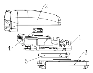
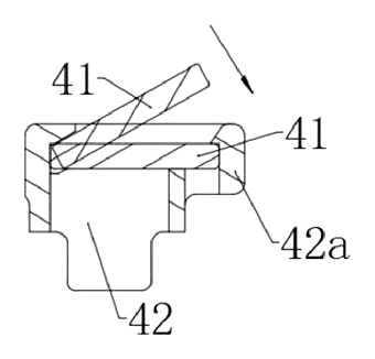
Drawings reproduced from the public patent document for reference.
Frequently asked questions
How does the buckle know if the belt is fastened?
It uses a Hall-effect sensor. When you insert the latch tongue, it mechanically moves a magnet assembly closer to the sensor. When the magnet aligns directly opposite the sensor, the electronic chip detects the magnetic field and sends a “locked” signal to the car’s computer. When released, the magnet moves away, and the signal changes to “unlocked.”
Why is the circuit board separate from the lock mechanism?
Separating the Printed Circuit Board Assembly (PCBA) into the lower shell prevents damage from the physical impact and vibration of the locking action. Mechanical switches often fail because they are part of the moving parts. Here, the sensor stays still while the magnet moves past it, improving long-term reliability.
Is it difficult to repair if the electronics fail?
No. Because the PCBA is snapped into the lower cover shell, you can access and replace the electronic module by removing the lower shell. You do not need to disassemble the complex lock core assembly, which saves time and reduces the risk of damaging the safety mechanism during repairs.
Does this work with all car systems?
The buckle outputs a standard electrical signal via wires. It must be compatible with the specific voltage and communication protocol of the vehicle’s body control module. Custom connectors or adapter harnesses may be needed depending on the car manufacturer.
Can it be used in commercial trucks?
Yes. The robust design handles higher vibration levels common in heavy machinery and trucks. However, commercial fleets should verify that the signal integration meets their telematics or safety monitoring software requirements.
What materials are used for the shells?
The patent describes cover shells that snap together. In production, these are typically made from high-impact engineering plastics like PA66 or ABS to withstand temperature extremes and physical stress. Metal variants are possible but require different tooling.
Can this design be made and sold in the US?
The patent is in force in China. The public record shows no US counterpart, so this specific patent does not restrict making or selling the design in the US. However, automotive safety components are subject to other global patents and strict federal regulations (FMVSS). We recommend a freedom-to-operate check and regulatory review before production.
Are you affiliated with the patent owner?
No. IP2M is an independent design and manufacturing service working from the public patent document.
Request a quote
Click Request a Quote below to see our email address - copy it, or open your email app with a ready-made message. Please mention patent CN111358122B in the subject.
Helpful details to include:
- Your company and channel (automotive supplier, EV manufacturer, aftermarket retrofit, industrial equipment maker)
- Vehicle platform or application type
- Connector specifications and signal requirements
- Quantity and target price
- Timeline - when you would like prototypes and validation samples
You can also reach us at (332) 203-9997.
Page editor: Daniel Chen, Product Research Editor · IP2M
Last updated November 5, 2026. If something on this page looks wrong, email [email protected] and we will check it against the patent.
Interested in building this?
Tell us your target market, quantity and timeline. We reply with options for prototyping, small-batch runs or volume production.
Send your inquiry to
Please put CN111358122B in the subject line and tell us your company, country, estimated quantity and timeline.
Prefer to talk? Call (332) 203-9997.
More product-ready patents
All Apparel & Accessories patents →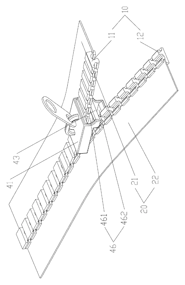
Apparel & Accessories
Stacked Zipper with Teeth That Mesh Top-to-Bottom
Zipper whose two identical tooth rows mesh on top of each other, closed by a simplified slider.
Patent CN205795062U
Apparel & Accessories
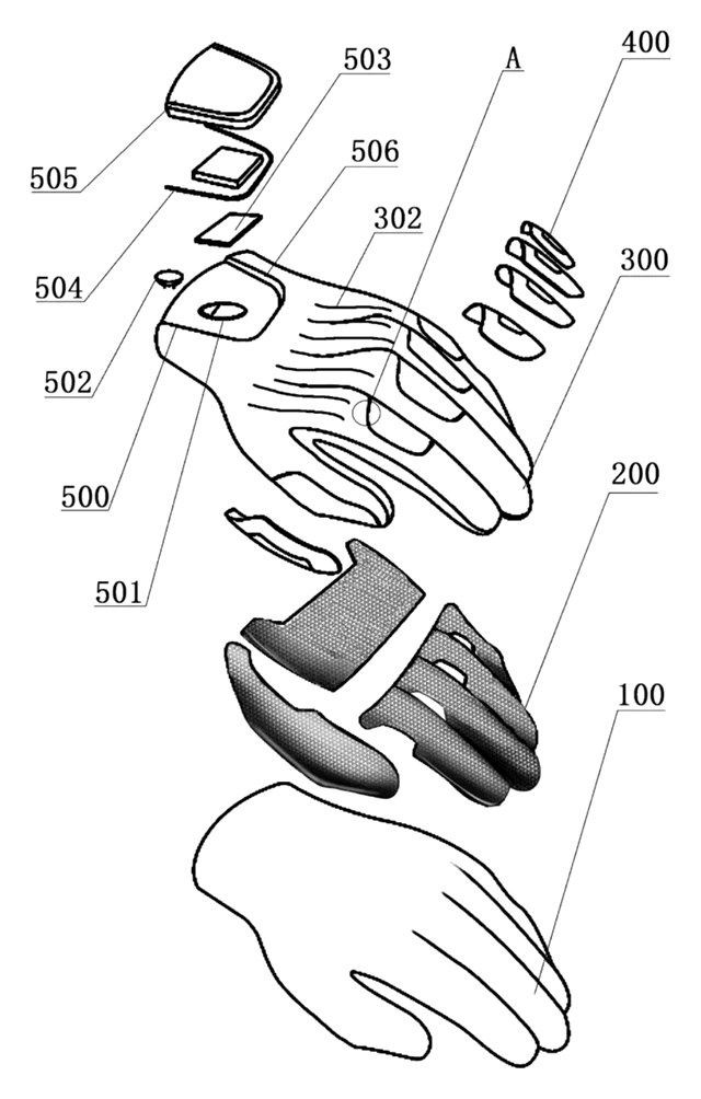
Impact-Resistant Glove with a 3D-Printed Lattice Layer
Work glove with a 3D-printed lattice impact layer, TPU knuckle guards and a light mounting area.
Patent CN213785583U
Apparel & Accessories
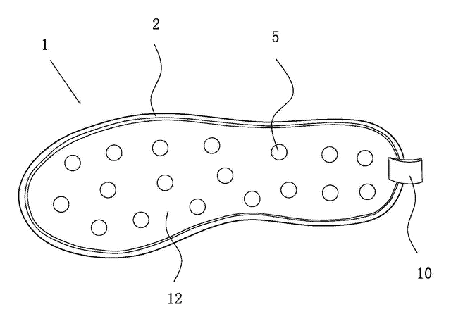
Massage Insole with Spring-Back Silicone Nubs and a Removable Top Layer
Layered insole: silicone nubs rise through a removable perforated top sheet and sink under each step.
Patent CN208286505U
Apparel & Accessories
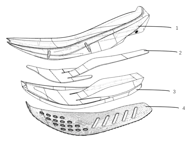
Heel-Less Carbon Plate Running Shoe Sole for Forefoot Strikers
Running sole for forefoot strikers: no ground-touching heel, winged carbon plate between two midsoles.
Patent CN216723354U
Apparel & Accessories
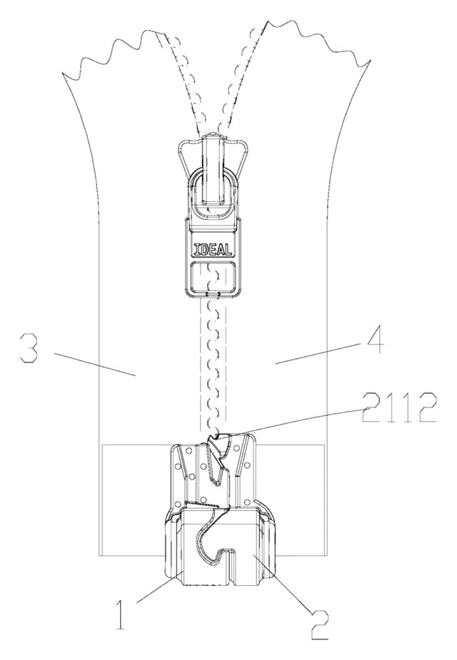
Waterproof Magnetic Zipper Stop That Snaps the Two Halves Together
Separating-zipper stop with sealed magnets: pin and box snap together one-handed, safe in rain and wash.
Patent CN215075936U
Apparel & Accessories
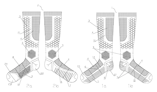
Left-Right Specific Soccer Socks: Grip for the Plant Foot, Touch Pads for the Kicking Foot
Soccer socks knitted as a left-right pair: grip zones for the plant foot, pads for the kicking foot.
Patent CN212728807U
Browse by category
- Apparel & Accessories (41)
- Baby & Kids (26)
- Bags & Luggage (15)
- Bath & Personal Care (27)
- Car Accessories (22)
- Furniture, Bedding & Storage (21)
- Garden & Outdoor (29)
- Health & Wellness (12)
- Home, Kitchen & Cleaning (44)
- Lighting (21)
- Packaging & Containers (11)
- Pet Products (10)
- Phone & Camera Accessories (8)
- Retail Display (22)
- School, Office & Art (31)
- Sports & Recreation (40)
- Tools & Workshop (49)
- Toys & Games (20)
This page is based on the public patent document CN111358122B, assigned to Shenyang Jinbei Jinheng Automotive Safety System Co ltd. IP2M is an independent manufacturing service and is not affiliated with, endorsed by or licensed by the patent owner. Images marked as concept renderings are illustrations, not photos of an existing product. Patent status information is provided for reference only and is not legal advice; confirm freedom to operate for your market before production. Full disclaimer.