
Patent CN111588160B
Updated October 31, 2026Hair Dryer with Conical Air Duct Sleeve for Streamlined Intake
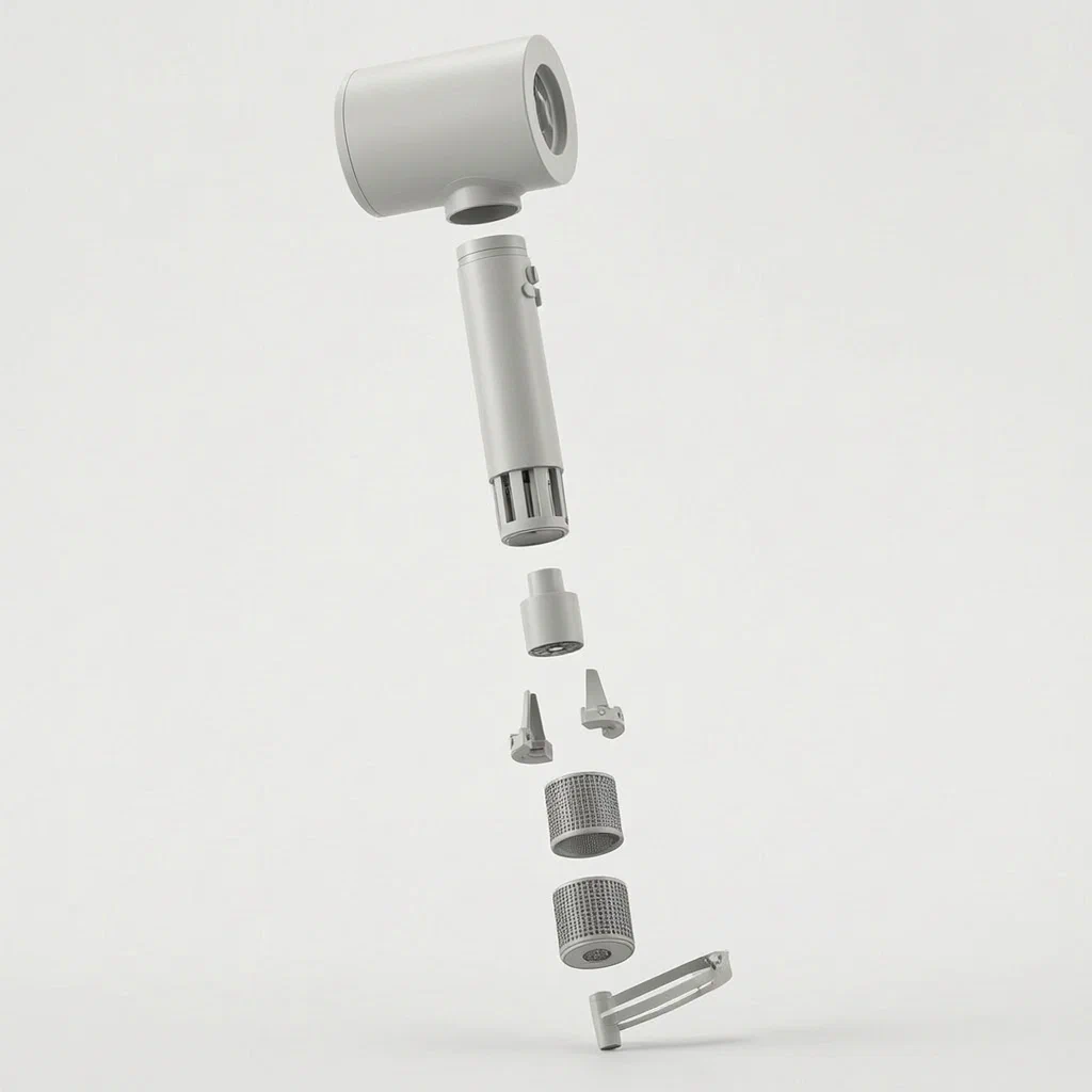
Standard hair dryers often suffer from turbulent air intake at the bottom of the handle, where air hits internal components randomly before reaching the fan. This creates noise and reduces suction efficiency. This patent describes a solution using a conical air duct sleeve placed inside the handle's hollow intake zone. The large end of the cone connects to the power cord clamp, while the small end points toward the fan blades. As air enters through the filter screen, it strikes the sleeve and flows along its sloped outer walls. This guides the air into a structured flow layer, accelerating the intake speed and reducing resistance before the air reaches the heating element and nozzle.
- China invention patent - lapsed
- No filings outside China
- Personal care appliances
- Conical air guide, plastic/metal composite sleeve
Splat! What let you down?
🌬️
Streamlined Intake
The conical sleeve guides air along its walls, turning chaotic entry into a smooth flow layer.
🔩
Integrated Cord Clamp
The sleeve connects directly to the power cord clamp, securing the cable while shaping airflow.
🛡️
Filter Protection
An external filter screen covers the intake holes, protecting the internal motor and sleeve.
⚡
Efficient Flow
By directing air to the fan blades more effectively, the design aims to accelerate intake speed.
Bring this product to market
- ✓ Patent vetted China-only family and legal status checked
- 2 Product brief · now How it works, uses and options written up
- 3 Prototype First samples for buyers to review
- 4 Pilot run Small first batch for launch customers
- 5 Volume production Repeat orders at scale
Buyer interest
– of 100 buyers needed to start prototyping
One click, no sign-up. Each vote is one real visitor, and products with the most interest go to prototyping first.
Build team: no members yet. Need a partner, co-funding or skills to build this? Join and we introduce the team once it forms.
The problem
In many handheld hair dryers, the air intake at the base of the handle is an open space where air rushes in without guidance. When the motor runs, it sucks air from all directions through the filter screen. This unguided flow can be turbulent; air collides with the internal motor housing or the back of the fan blades in a disorganized manner. This turbulence can create unnecessary noise, reduce the efficiency of the suction, and potentially cause uneven wear on the fan assembly. Additionally, managing the power cord entry point so it does not obstruct this airflow path is a common structural challenge in compact designs.
The solution
This patent proposes a specific internal structure for the hair dryer handle to manage these issues.
- The handle has a hollow section at the bottom, covered by a filter screen with multiple inlet holes.
- Inside this hollow section is a conical air duct sleeve. Its wide end is fixed to a power cord clamp, and its narrow end points toward the motor’s fan blades.
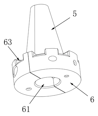
- The power cord clamp is an annular (ring-shaped) structure located at the tail of the hollow section. It holds the power cord securely.
- A threading hole allows the power cord to pass through the connection between the sleeve and the clamp.
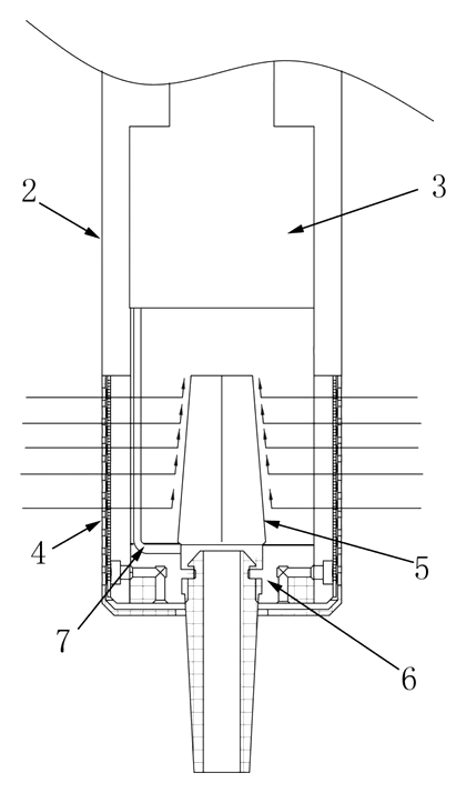
- When air enters through the filter, it hits the conical sleeve. Instead of swirling chaotically, the air moves along the outer wall of the cone.
- This movement organizes the air into a “wind flow layer,” guiding it smoothly toward the fan blades and increasing the intake speed.
Who it is for
- Appliance Manufacturers: Brands looking to improve airflow efficiency and reduce noise in standard consumer hair dryers without changing the overall size.
- Industrial Designers: Teams seeking a structural way to integrate power cord management with aerodynamic improvements in the handle.
- OEM Suppliers: Factories producing personal care devices that need a patented or distinct internal structure to differentiate their products in the market.
- Product Engineers: Specialists focusing on fluid dynamics within small household appliances who want to minimize turbulence at the intake stage.
How it works
The main parts
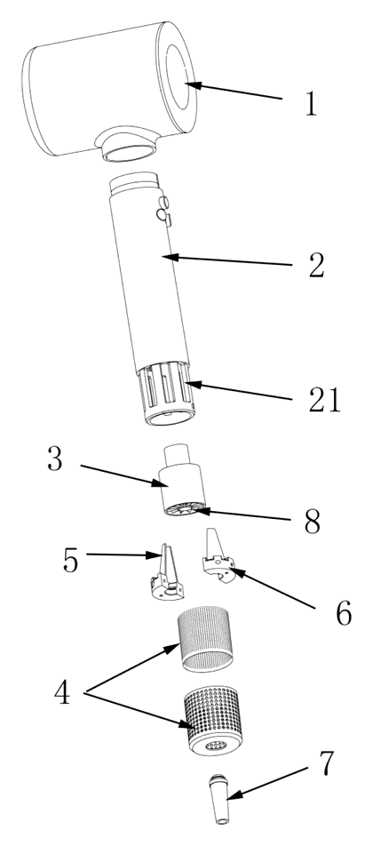
| No. | Part | What it does |
|---|---|---|
| 1 | Blower Barrel | The front part of the dryer where air exits. |
| 2 | Handle | Contains the motor and the hollow intake section. |
| 21 | Hollow Structure | The empty space below the handle where air enters. |
| 3 | Motor | Located inside the handle, driving the fan. |
| 4 | Filter Screen | Covers the hollow structure; has multiple inlet holes. |
| 5 | Air Duct Sleeve | Conical shape inside the hollow structure; guides air. |
| 6 | Power Cord Clamp | Annular ring holding the cord; attached to the sleeve. |
| 7 | Power Line | Passes through the threading hole and clamp. |
| 8 | Fan Blade | Attached to the motor shaft; draws in guided air. |
Operating Steps
- Activation: The user switches on the hair dryer, causing the motor to spin the fan blades.
- Intake Start: Air is drawn in from the environment through the multiple holes in the external filter screen.
- Guidance: The incoming air encounters the conical air duct sleeve. Because of the cone’s shape, the air is deflected to flow along the outer surface of the sleeve.
- Flow Layering: This deflection turns the scattered air into a coherent flow layer directed toward the center.
- Acceleration: The guided flow reaches the fan blades with higher velocity and less turbulence than unguided intake.
- Heating/Exit: The air passes through the heating element (if active) and exits through the blower barrel nozzle.
Applications
Consumer Hair Styling
Home users benefit from a quieter operation and potentially faster drying times due to improved airflow consistency. The integrated cord clamp also makes the device feel sturdier during daily use.
Professional Salon Tools
Stylists use hair dryers for extended periods. A design that reduces intake turbulence can lower the noise floor in busy salons and provide a more consistent wind pressure, which is critical for precise styling techniques.
Travel and Compact Devices
For smaller, travel-sized dryers where internal space is limited, this structure offers a way to maximize the efficiency of the available intake area without requiring larger fans or motors, keeping the unit compact.
High-Performance Appliances
Manufacturers aiming for high CFM (cubic feet per minute) ratings can use this geometric guide to ensure that the maximum amount of air entering the filter is efficiently captured by the fan, rather than being lost to eddies or dead zones.
Where it is less suitable
- Ultra-Low-Cost Disposable Dryers: The added complexity of the molded sleeve and dual-material clamp (plastic/metal) may increase production costs beyond the budget of single-use or very cheap items.
- Non-Motorized Accessories: This patent specifically addresses active airflow generation via a motor; it does not apply to passive diffusers or attachment-only tools.
- Sealed Motor Designs: If a manufacturer uses a completely sealed motor housing with side intakes rather than bottom intakes, this specific sleeve geometry would not fit the airflow path.
Frequently asked questions
What is the purpose of the conical sleeve?
The sleeve acts as an aerodynamic guide. Instead of air rushing chaotically into the fan, it hits the cone and slides along its walls. This organizes the air into a smoother flow layer, which helps accelerate the intake speed and reduces turbulence and noise.
Is the sleeve made of metal or plastic?
According to Claim 4, the patent describes the power cord clamp as plastic and the air duct sleeve as metal. They are inlaid together. However, in custom manufacturing, both could potentially be made of high-grade heat-resistant plastics depending on the thermal load and cost targets.
How does it handle the power cord?
The sleeve is connected to an annular power cord clamp at the bottom of the handle. The cord passes through a threading hole and is secured by a clamping ring in the middle of the clamp. This keeps the cord stable and prevents it from blocking the air intake path.
Does this design make the dryer hotter?
The patent focuses on airflow efficiency. By guiding air more effectively to the heating element and fan, it may help maintain consistent temperatures. However, proper thermal management still depends on the heater design and ventilation, which are separate from this specific sleeve structure.
Can I change the angle of the cone?
Yes. The cone angle can be optimized for different fan sizes and motor speeds. Our engineering team can simulate various geometries to find the best balance between airflow acceleration and pressure drop.
Is this safe for home use?
The design itself is mechanical. Safety depends on the overall electrical system. For US sales, the final product must pass UL 859/1082 standards, including tests for overheating, electric shock, and fire resistance. We assist in ensuring the materials and assembly meet these requirements.
Can this design be made and sold in the US?
The patent was filed only in China and has lapsed due to non-payment of fees. It does not restrict the design in the US. However, hair dryer technology is heavily patented globally. We strongly recommend a freedom-to-operate (FTO) search to ensure your specific version doesn’t infringe on active US patents held by major appliance manufacturers.
Are you affiliated with the patent owner?
No. IP2M is an independent design and manufacturing service working from the public patent document.
Request a quote
Click Request a Quote below to see our email address - copy it, or open your email app with a ready-made message. Please mention patent CN111588160B in the subject.
Helpful details to include:
- Your company and channel (appliance brand, OEM factory, retail importer)
- Target airflow (CFM or L/s) and motor specifications
- Handle dimensions and weight constraints
- Material preferences (e.g., aluminum sleeve, ABS clamp)
- Estimated quantity and target price
- Timeline - when you would like prototypes and mass production start
You can also reach us at (332) 203-9997.
Explore this product
Interested in building this?
Tell us your target market, quantity and timeline. We reply with options for prototyping, small-batch runs or volume production.
Send your inquiry to
Please put CN111588160B in the subject line and tell us your company, country, estimated quantity and timeline.
Prefer to talk? Call (332) 203-9997.
More product-ready patents
All Bath & Personal Care patents →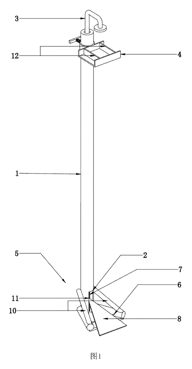
Bath & Personal Care
Foot-Pedal Soap & Sanitizer Dispenser Stand
Hands-free, battery-free dispenser stand - step on a pedal to press the pump of any soap or sanitizer bottle.
Patent CN207461995U
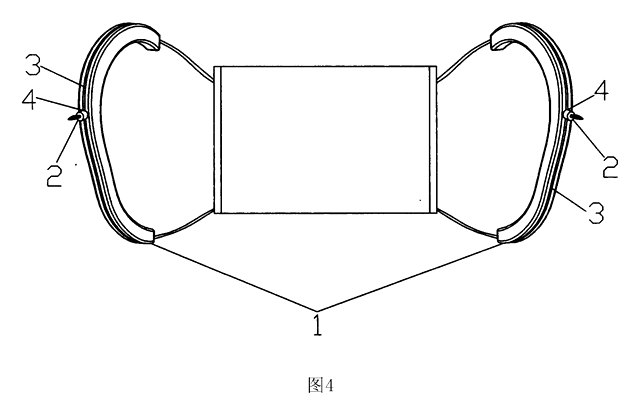
Bath & Personal Care
Ear-Shaped Mask Strap Guard with Tension Adjuster
Ear-shaped silicone guard and strap-length adjuster that make ear-loop masks comfortable to wear for long hours.
Patent CN205456233U
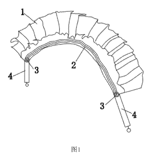
Bath & Personal Care
Adjustable-Length Back Scrubber Strap with Push-Button Handles
Back-scrubber strap with push-button handles that set its length and a spring that keeps it taut.
Patent CN207041452U
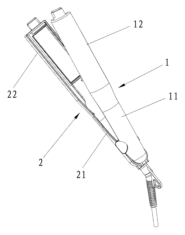
Bath & Personal Care
Angled-Plate Hair Straightener
Flat iron with plates twisted 45-75° to the handle, a curling groove and rubber-capped tips.
Patent CN206137462U
Bath & Personal Care
Refillable Lipstick Case with Sealed Snap-In Refill Pods
Reusable twist-up lipstick case; sealed refill pods unlock at the top of the stroke for shade swaps.
Patent CN206909979U
Bath & Personal Care
Quick-Release Toilet Seat Hinge with a Push-Button Two-Strip Latch
Toilet seat hinge: drop the shaft onto a grooved post to lock; one push parks the latch open to lift it off.
Patent CN210370292U
Browse by category
- Apparel & Accessories (23)
- Baby & Kids (18)
- Bags & Luggage (12)
- Bath & Personal Care (18)
- Car Accessories (14)
- Furniture, Bedding & Storage (13)
- Garden & Outdoor (19)
- Health & Wellness (9)
- Home, Kitchen & Cleaning (27)
- Lighting (13)
- Packaging & Containers (7)
- Pet Products (6)
- Phone & Camera Accessories (4)
- Retail Display (15)
- School, Office & Art (20)
- Sports & Recreation (26)
- Tools & Workshop (32)
- Toys & Games (13)
This page is based on the public patent document CN111588160B, assigned to Best Fire Technology Hangzhou Co ltd. IP2M is an independent manufacturing service and is not affiliated with, endorsed by or licensed by the patent owner. Images marked as concept renderings are illustrations, not photos of an existing product. Patent status information is provided for reference only and is not legal advice; confirm freedom to operate for your market before production. Full disclaimer.