
Patent CN112277754B
Updated November 8, 2026Automated Disposable Cup Dispenser for Vehicle Armrest Boxes
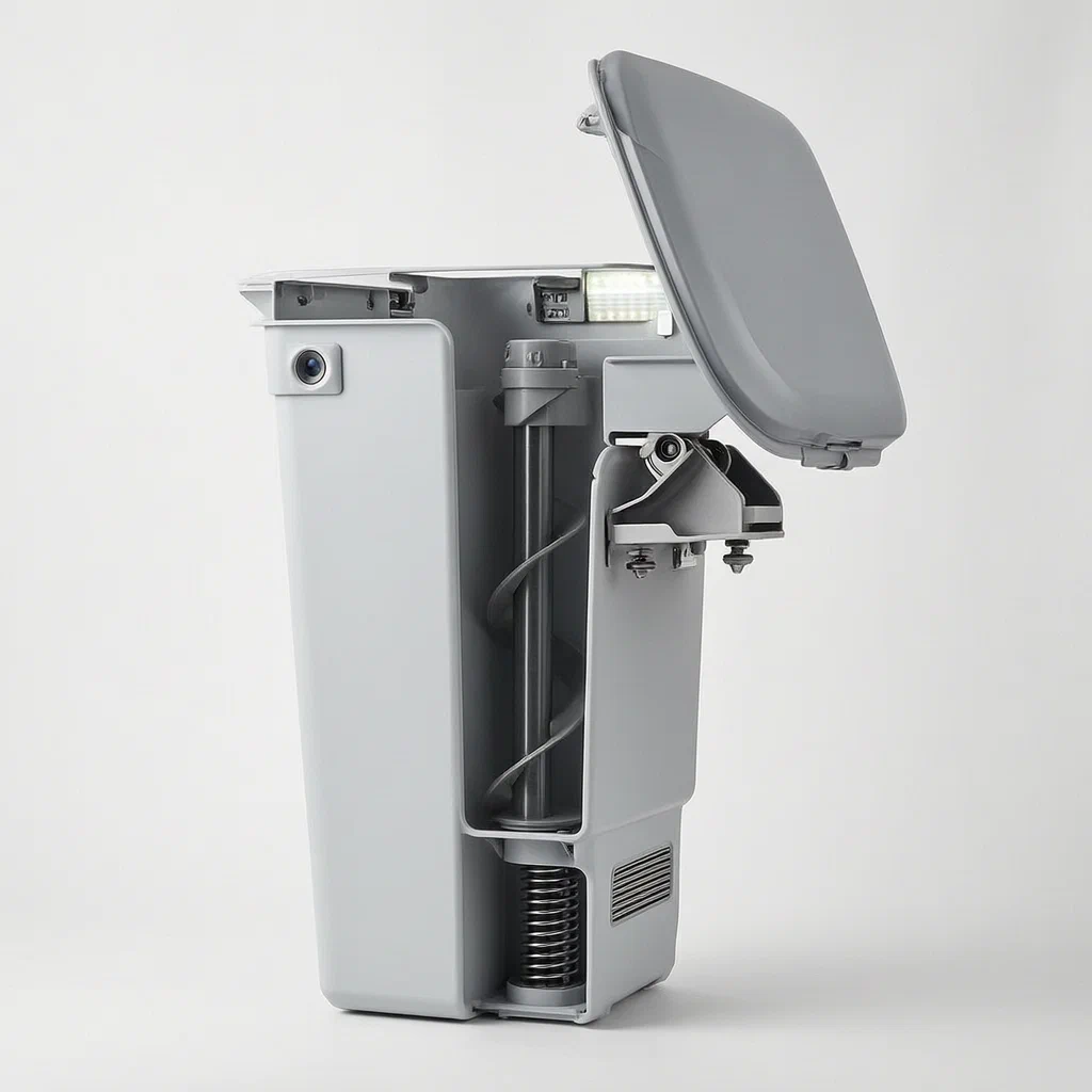
Keeping spare paper cups in a glovebox often leads to crushed edges, dust contamination, and messy retrieval. This patent describes an automated dispenser built into the vehicle's armrest box. Vertical spiral augers rotate to slip between stacked cups, separating them individually. A clamping mechanism then lifts the top cup up through a guide channel until it emerges above the armrest lid. Integrated UV lights help keep the stored cups clean before use.
- China invention patent - In force
- No filings outside China
- Vehicle interior accessories
- Spiral auger separation, clamping conveyance, UV disinfection
Splat! What let you down?
🌀
Spiral Auger Separation
Vertical rotating spirals insert between cup rims to separate stacked cups one by one.
🤖
Clamping Conveyance
Motor-driven claws grab the top cup and lift it through a guide channel to the surface.
☀️
UV Disinfection
Ultraviolet lamps in the housing illuminate the cup transfer path for hygiene.
📏
Proximity Sensing
Sensors detect when a cup reaches the delivery platform to stop the cycle.
Bring this product to market
- ✓ Patent review Patent family and legal status reviewed in the relevant jurisdictions.
- 2 Product brief · now How it works, uses and options written up
- 3 Prototype First samples for buyers to review
- 4 Pilot run Small first batch for launch customers
- 5 Volume production Repeat orders at scale
Buyer interest
– of 100 buyers needed to start prototyping
One click, no sign-up. Each vote is one real visitor, and products with the most interest go to prototyping first.
Build team: no members yet. Need a partner, co-funding or skills to build this? Join and we introduce the team once it forms.
Patent Rights & Team Participation
Before joining a development team, participants should ensure they have the necessary rights or authorization to participate in the project.
Participation is generally appropriate where:
- You own the relevant patent rights or have obtained permission or a license from the rights holder.
- The relevant patent rights have expired or have been legally invalidated in the jurisdictions where the planned activities will take place.
- The planned development, manufacturing, and commercialization activities have been independently assessed and do not infringe applicable patent rights in the relevant jurisdictions.
Important: Being located outside a country where a patent is protected does not automatically exempt you from patent infringement risks. Patent rights may apply based on where development, manufacturing, use, sale, or import activities take place.
IP2M does not grant any patent license or authorization through team participation. Joining a project does not provide permission to use, manufacture, or commercialize patented technology.
The problem
Storing spare disposable cups loosely in a vehicle’s glovebox or center console causes several issues. Cups get crushed by heavy items, accumulate dust, and are difficult to retrieve without pulling out the entire stack. For commercial fleets, ride-hailing services, or long-distance transport, providing clean, accessible water for passengers requires a dedicated solution that does not clutter the cabin or risk contamination. Existing manual dispensers often jam or fail to separate nested cups reliably.
The solution
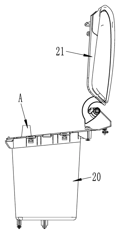
This device integrates directly into the vehicle’s front armrest box. It solves the separation and access problem through a two-stage mechanical process.
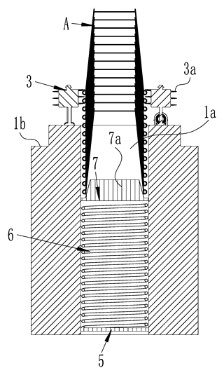
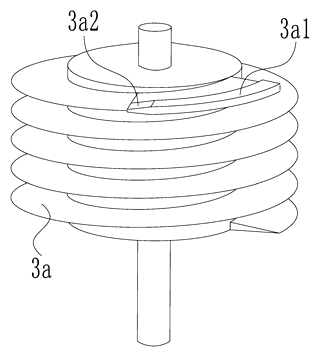
- Storage and Separation: A bucket holds a stack of disposable cups. Multiple vertical spiral augers rotate around the upper opening. As they turn, the spiral ribs insert between the flared rims of the cups, pushing them apart so only the topmost cup remains isolated.
- Lifting Mechanism: A spring-loaded plate pushes the stack upward against the augers. When a cup is separated, a clamping assembly grabs it and lifts it vertically through a central channel until it protrudes above the armrest lid, ready for the user to take.
Who it is for
- Ride-hailing and Taxi Fleets: Drivers need a hygienic way to offer water to passengers without reaching into a dirty bag.
- Commercial Vehicle Manufacturers: OEMs looking to add premium convenience features to interior consoles.
- Fleet Management Companies: Operators wanting to standardize passenger amenities in long-haul trucks or buses.
- Aftermarket Accessory Brands: Sellers offering smart interior upgrades that replace standard armrest lids.
How it works
The main parts
The device consists of a cup dividing mechanism and a cup discharging mechanism housed within a protective shell.
| No. | Part | What it does |
|---|---|---|
| 1 | Cup Storage Bucket | Holds the stack of disposable cups; has an upper opening. |
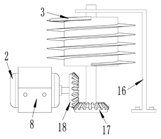
| 3 | Spiral Auger | Vertical screw-like component with spiral ribs (3a) that rotate to separate cups. |
| 2 | Auger Motor | Drives the rotation of the spiral augers via bevel gears. |
| 5, 6, 7 | Jacking Assembly | Support plate, pressure spring, and lifting plate push the cup stack upward. |
| 4 | Discharge Support | Frame with a transfer passage (4a) leading to the top exit. |
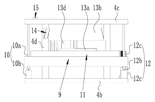
| 9, 10 | Annular Base & Screws | Lifting mechanism that raises the clamping assembly. |
| 11, 13 | Driving Ring & Claws | Rotating ring moves hinged claws (13b) to grip or release the cup. |
| 14 | One-way Stopper | Elastic fingers that form a platform to hold the lifted cup. |
| 23 | UV Lamp | Disinfects the area around the transfer passage. |
Operating Steps
- Initiation: The user presses a switch button on the armrest lid.
- Separation: The auger motors spin the spiral augers. The ribs slide between the nested cup rims, forcing the lower cups down while isolating the top cup. Simultaneously, the spring-loaded base pushes the stack up.
- Gripping: The clamping assembly descends or aligns with the top cup. The driving ring rotates, causing the hinged claws to close around the cup body.
- Conveyance: The lead screws raise the annular base, lifting the gripped cup up through the transfer passage.
- Delivery: The cup passes through the one-way stoppers, which flex outward to let it pass, then snap back to support the cup at the exit level. The cup protrudes above the armrest for easy removal.
Applications
Ride-Hailing Service Vehicles
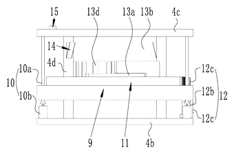
Drivers can provide bottled water or coffee cups to passengers instantly. The enclosed system keeps the cups clean and free from dust accumulated in the cabin, enhancing the service experience without requiring the driver to leave the seat.
Long-Haul Trucking Cabins
Truckers spend many hours on the road. Having immediate access to fresh drinking cups without digging through a cooler or bag reduces distraction. The UV lamps described in the patent are intended to help keep the cups sanitary during long shifts.
Fleet Management Amenities
Corporate shuttle buses or rental cars can offer complimentary beverages. The automated dispenser prevents waste by releasing only one cup per press, unlike open boxes where users might take multiple cups unnecessarily.
Luxury Interior Upgrades
High-end aftermarket kits can replace standard armrest boxes with this functional unit. It adds a “smart car” feel to older models, appealing to buyers who value integrated technology and convenience features in their daily commute.
Where it is less suitable
- Vehicles with shallow armrests: The mechanism requires vertical depth for the augers and lifting assembly; slim consoles may not accommodate the height.
- Non-standard cup sizes: The spiral spacing and claw geometry are tuned for specific disposable cup diameters; custom tooling would be needed for different brands.
- Extreme heat environments: While the production plastic is likely ABS or PC, prolonged exposure to direct sunlight in hot climates could affect plastic durability or adhesive bonds over time.
Patent & Production
At a glance
| Patent number | CN112277754B (application CN202011208712) |
| Type | China invention patent (发明专利) - protects product shape, structure, and method |
| Original title | Vehicular cup feeding and discharging device and automobile front-seat handrail case (车用上出杯装置及汽车前排扶手箱) |
| Patent owner | Chongqing Technology and Business Institute |
| Inventors | Wei Xiankun, Yang Xingguo, Deng Changyong, Fan Yingjie |
| Filing date | 2020-11-03 |
| Grant date | 2021-10-22 |
| Status (China) | In force - valid until at most 2040-11-03 (if annual fees are paid) |
| Patent family | Public record shows Chinese filings only - no US, European, Japanese, PCT or other filings listed |
| Cited by | 0 later documents |
| Source | Google Patents (search for CN112277754B) |
What the claims cover, in plain language
Claim 1 - A vehicular cup feeding and discharging device comprising a cup dividing mechanism and a cup discharging mechanism. The dividing mechanism includes a storage bucket with an upper opening and at least two sets of spiral augers arranged around the opening. Each auger set has a motor-driven spiral auger with spiral ribs that protrude into the bucket. When rotated, these ribs insert between stacked disposable cups to separate them one by one. A jacking assembly at the bottom pushes the cups upward. The discharging mechanism includes a support frame with a transfer passage connected to the bucket. A clamping and conveying assembly grabs the separated top cup and transports it to a cup bearing platform at the top of the passage.
Claims 2-4 - Details the drive system (bevel gears), and the specific shape of the spiral ribs (expansion sections and gradual sections) to improve separation reliability. Claims 5-7 - Describe the one-way stoppers forming the platform, the mechanics of the clamping claws (driven by a rotating ring and lead screws), and the spring-loaded jacking assembly. Claim 8 - Integrates the device into an automobile front-seat handrail case (armrest box). The device is housed in a shell below the lid, with a switch button on the discharge mechanism. Claims 9-10 - Add ultraviolet disinfection lamps in the installation chamber to irradiate the transfer passage, and proximity sensors to detect the cup position.
This is a simplified reading for orientation only. The legal scope is defined by the exact claim wording in the official Chinese document.
What this means for US production
This patent was filed in China and is currently in force. The public record shows no US or other foreign counterpart.
Two points to settle early:
- Other patents may exist. Automotive interior accessories and vending mechanisms are complex fields. While this specific combination of spiral augers and clamping claws appears unique to this filing, prior art in automatic beverage dispensers or cup stacks exists globally. A freedom-to-operate (FTO) review is recommended to ensure no existing US patents block similar functionality.
- Integration complexity. Manufacturing this requires coordinating electronics (motors, sensors, UV lights) with precision mechanical parts (augers, gears, claws). Tolerances must be tight enough for smooth operation but loose enough to handle thermal expansion in a car cabin.
Customization and manufacturing
What can be customized
| Area | Options |
|---|---|
| Cup Size | Spiral pitch and claw diameter set for the cup sizes you specify (confirmed on prototypes). |
| Materials | ABS or PC for housings; stainless steel or POM for augers and gears (to be confirmed in design). |
| Power Source | 12V DC input (standard car battery) or internal rechargeable battery pack. |
| Controls | Physical button, touch panel, or integration with vehicle CAN bus. |
| Finish | Matte black, textured gray, or color-matched to vehicle interior trim. |
| Hygiene | Additional UV-C lamp placement or wavelength options. |
Things to plan for (US market)
- FMVSS 302 - Flammability requirements for automotive interior materials. All plastics and adhesives must meet burn rate standards.
- EMC Compliance - Motors and electronic controllers must not interfere with vehicle radios or sensitive electronics (typically tested to CISPR 25 or similar).
- Temperature Range - Components must operate reliably from -20°C to +80°C, typical for automotive cabins.
- Safety Standards - Ensure pinch points in the clamping mechanism do not pose injury risks, especially if accessible to children.
How a project runs
- Inquiry - Define target cup sizes, power requirements, and vehicle model dimensions.
- Design - CAD modeling of auger geometry, gear ratios, and housing fitment.
- Prototype - 3D-printed functional units to test separation reliability and lift force.
- Pilot Run - Small batch production for durability testing (cycles, heat, vibration).
- Production - Injection molding for shells, machining for metal parts, sub-assembly of motors and PCBs.
Quantities & timeline
Injection molds for the housing, augers, and claws are the critical path. Electronic components require sourcing time. Functional prototyping is critical to tune the spiral rib angle for different cup brands. Send us your target cup size, power spec, quantity, and target price and we will reply with options.
Patent drawings
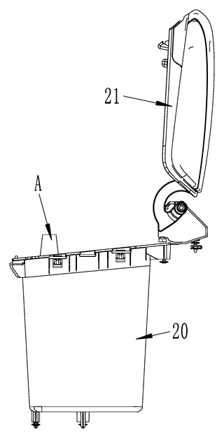
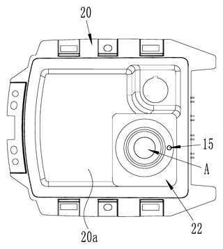
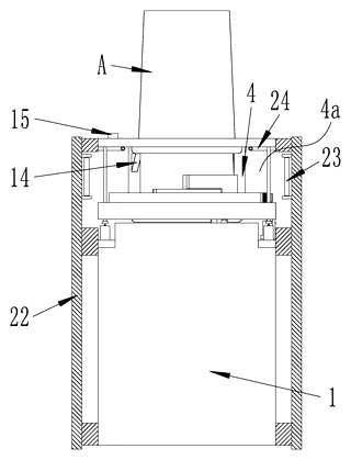
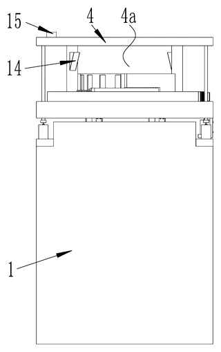
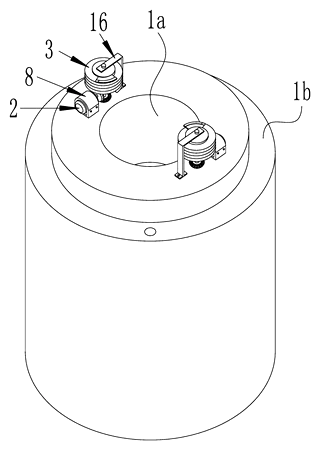
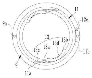
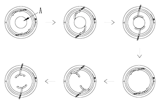
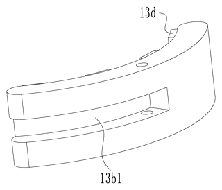
Drawings reproduced from the public patent document for reference.
Production notes
Tooling and process
Injection molding is likely required for the housing, augers, and claw arms using ABS or PC. Metal gears and shafts typically involve aluminum machining and zinc alloy castings. Motor and sensor assemblies typically require PCB assembly.
Cost drivers
Tooling complexity is typically high due to the interlocking spiral and clamping geometries. Assembly tolerance affects performance significantly; misaligned augers cause jams. Heat-resistant material grades increase raw material costs for automotive use.
Prototyping path
We typically start with 3D-printed fit checks in a mock armrest box. Create functional samples to test cup separation rates. Conduct heat-cycle samples to verify plastic stability under cabin temperatures. Adhesive trials are needed for securing friction pads.
What we would change before tooling
We would likely adjust the spiral rib pitch based on prototype jamming tests. Optimize wall thickness and joint design to reduce weight without sacrificing rigidity. Verify wire routing and strain relief for the UV lamp and sensors to prevent breakage during movement.
Common failure points
Deformation in cabin heat can warp the transfer channel. Poor fit at gaps allows dust ingress. Shaft and bearing alignment issues cause motor noise. Spring fatigue in the jacking assembly reduces lift force over time. Rattle at joints occurs if tolerances are too loose.
Frequently asked questions
How does it separate the cups?
It uses vertical spiral augers that rotate. The spiral ribs slide between the rims of the stacked cups, pushing them apart so only the top cup is isolated for lifting.
What types of cups can it dispense?
The design targets standard disposable paper or plastic cups. The spiral pitch and claw size are fixed in the patent, but custom tooling can adjust these dimensions for the cup diameters you specify (confirmed on prototypes).
Does it work with any armrest box?
No. It is designed to integrate into a specific type of front-seat handrail case. Retrofitting requires modifying the existing armrest lid and ensuring there is sufficient vertical depth inside the console for the mechanism.
Is the cup kept clean?
Yes. The cups are stored in an enclosed bucket. The patent includes ultraviolet (UV) disinfection lamps in the transfer passage to sanitize the cup as it moves up, helping maintain hygiene.
How is it powered?
The patent describes electric motors for the augers and clamping assembly. In a real-world application, this would typically connect to the vehicle’s 12V DC power supply or use an internal battery pack.
Can I control it manually?
The patent specifies a switch button on the discharge mechanism. Pressing the button triggers the separation and lifting cycle. Advanced versions could integrate with vehicle electronics, but the core function is button-activated.
Can this design be made and sold in the US?
The patent is in force in China. The public record shows no US counterpart, so it does not restrict the design in the US. However, automotive accessories are heavily patented, so a freedom-to-operate check is recommended before mass production.
Are you affiliated with the patent owner?
No. IP2M is an independent design and manufacturing service working from the public patent document.
Request a quote
Click Request a Quote below to see our email address - copy it, or open your email app with a ready-made message. Please mention patent CN112277754B in the subject.
Helpful details to include:
- Your company and channel (fleet operator, auto accessory brand, interior designer)
- Target cup size (diameter and height)
- Power preference (12V hardwired or battery-powered)
- Quantity estimates for pilot or full production
- Timeline - when you would like prototypes and initial samples
You can also reach us at (332) 203-9997.
Page editor: Daniel Chen, Product Research Editor · IP2M
Last updated November 8, 2026. If something on this page looks wrong, email [email protected] and we will check it against the patent.
Interested in building this?
Tell us your target market, quantity and timeline. We reply with options for prototyping, small-batch runs or volume production.
Send your inquiry to
Please put CN112277754B in the subject line and tell us your company, country, estimated quantity and timeline.
Prefer to talk? Call (332) 203-9997.
More product-ready patents
All Car Accessories patents →
Car Accessories
Car Headrest Pillow with Ratchet Side Wings and Push-Button Reach
Post-mounted car headrest pillow with ratchet side wings and a push-button forward adjustment.
Patent CN212195197U
Car Accessories
Hard-Shell Rooftop Tent That Doubles as a Cargo Box
Roof box whose hard frames lift on gas struts into a tent with door and skylight, and fold back for luggage.
Patent CN206327275U
Car Accessories
Headlamp-to-Bumper Adapter Bracket That Sets Gap and Flush in Three Directions
Molded bracket under the headlamp: support blocks and snap teeth locate the bumper flange for an even gap.
Patent CN216580316U
Car Accessories
Infant Car Seat with a Load-Bearing Base That Wraps the Carrier
Infant car seat whose base has a backrest and swing-up side rails, so the carrier can be lighter.
Patent CN206383856U
Car Accessories
Retractable Side Impact Protection Block for Child Car Seats
Retractable side-impact block for child seats: springs out to provide side-impact buffering, folds flat.
Patent CN207028930U
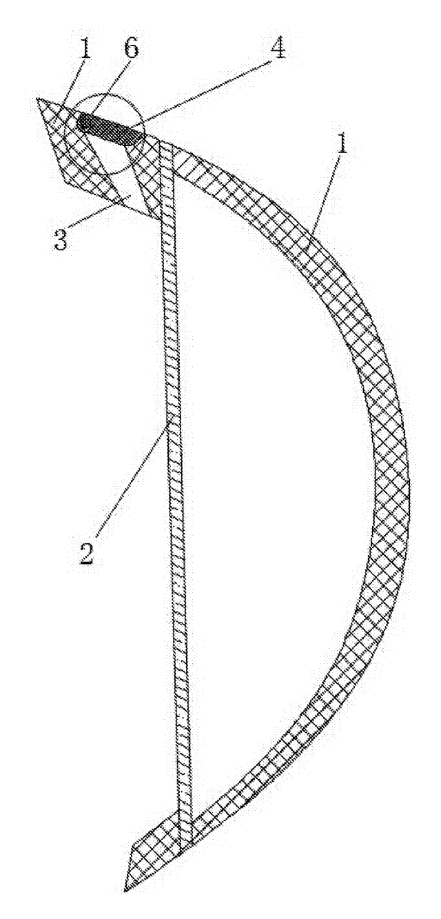
Car Accessories
Rain-Deflecting Side Mirror with a Pivoting Air-Guide Plate
Side mirror with a top air duct and folding guide plate that directs airflow across the glass.
Patent CN207345672U
Browse by category
- Apparel & Accessories (51)
- Baby & Kids (30)
- Bags & Luggage (17)
- Bath & Personal Care (33)
- Car Accessories (27)
- Furniture, Bedding & Storage (25)
- Garden & Outdoor (34)
- Health & Wellness (15)
- Home, Kitchen & Cleaning (52)
- Lighting (25)
- Packaging & Containers (13)
- Pet Products (12)
- Phone & Camera Accessories (10)
- Retail Display (27)
- School, Office & Art (38)
- Sports & Recreation (49)
- Tools & Workshop (57)
- Toys & Games (24)
This page is based on the public patent document CN112277754B, assigned to Chongqing Technology and Business Institute. IP2M is an independent manufacturing service and is not affiliated with, endorsed by or licensed by the patent owner. Images marked as concept renderings are illustrations, not photos of an existing product. Patent status information is provided for reference only and is not legal advice; confirm freedom to operate for your market before production. Full disclaimer.