
Patent CN112586483B
Updated November 5, 2026Box-Shaped Automated Mousetrap with Rotating Capture Mechanism
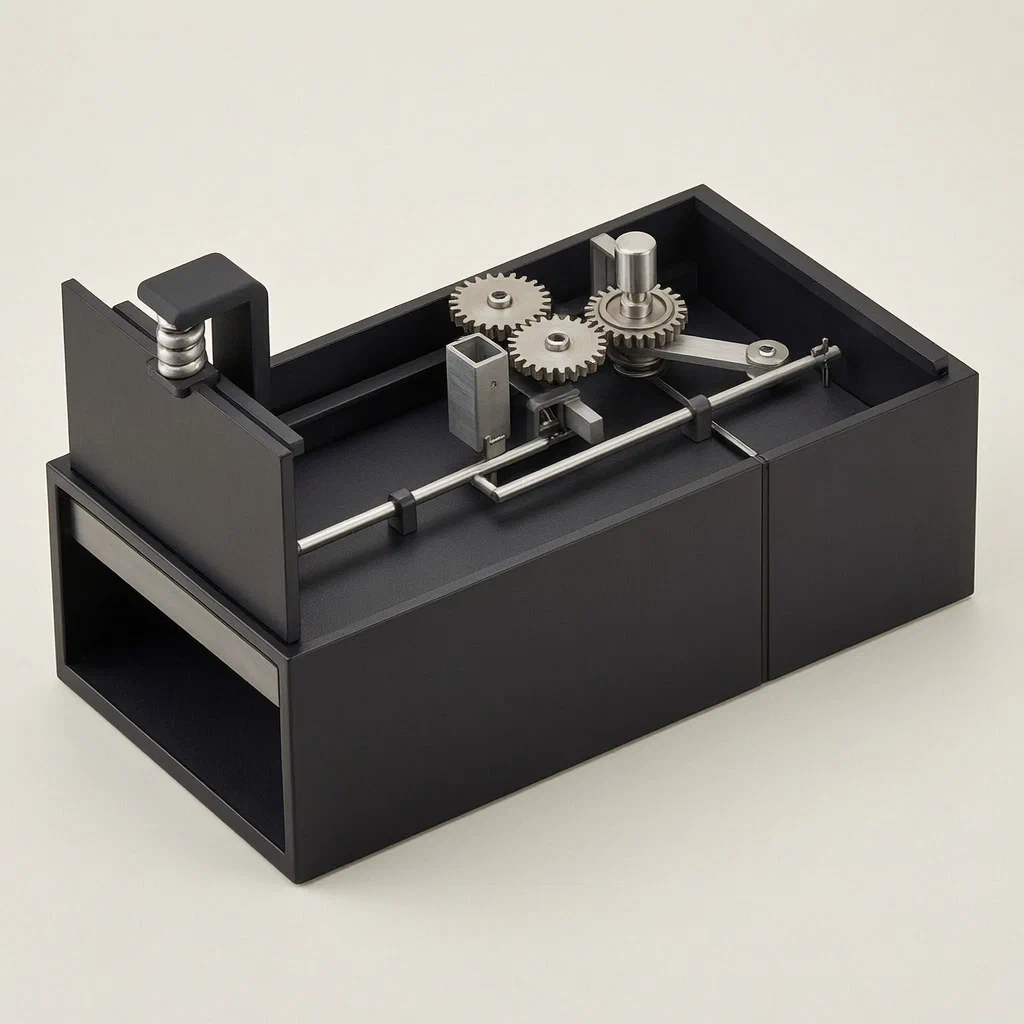
Traditional snap traps require frequent checking and can miss smaller rodents or fail to kill instantly. This automated box trap solves these issues by using a mechanical trigger to close a door upon entry, followed by a motorized rotation that isolates the captured mouse in a dedicated section. This design minimizes human contact with the rodent, simplifies disposal through a removable baffle, and allows for repeated use without manual resetting of every component. It is suitable for brands looking to offer a high-capacity, low-maintenance pest control solution.
- China invention patent - active
- No filings outside China
- Pest control equipment
- Motorized, spring-loaded, gear-driven
Splat! What let you down?
🔄
Auto-Reset Door
Spring-loaded sliding door closes on trigger and resets via gear mechanism.
⚙️
Rotating Guide
Motor-driven column rotates to isolate captured mice for easy removal.
📦
Removable Baffle
Side baffle slides up to allow disposal of trapped rodents.
🔋
Sealed Electronics
Motor and shafts housed within the box structure for protection.
Bring this product to market
- ✓ Patent review Patent family and legal status reviewed in the relevant jurisdictions.
- 2 Product brief · now How it works, uses and options written up
- 3 Prototype First samples for buyers to review
- 4 Pilot run Small first batch for launch customers
- 5 Volume production Repeat orders at scale
Buyer interest
– of 100 buyers needed to start prototyping
One click, no sign-up. Each vote is one real visitor, and products with the most interest go to prototyping first.
Build team: no members yet. Need a partner, co-funding or skills to build this? Join and we introduce the team once it forms.
Patent Rights & Team Participation
Before joining a development team, participants should ensure they have the necessary rights or authorization to participate in the project.
Participation is generally appropriate where:
- You own the relevant patent rights or have obtained permission or a license from the rights holder.
- The relevant patent rights have expired or have been legally invalidated in the jurisdictions where the planned activities will take place.
- The planned development, manufacturing, and commercialization activities have been independently assessed and do not infringe applicable patent rights in the relevant jurisdictions.
Important: Being located outside a country where a patent is protected does not automatically exempt you from patent infringement risks. Patent rights may apply based on where development, manufacturing, use, sale, or import activities take place.
IP2M does not grant any patent license or authorization through team participation. Joining a project does not provide permission to use, manufacture, or commercialize patented technology.
The problem
Standard snap traps and glue boards have significant drawbacks for professional pest control and home users. Snap traps often fail to catch small rodents, pose a risk to children or pets if mishandled, and require direct contact with dead mice during disposal. Glue boards are messy, considered cruel by many consumers, and lose effectiveness quickly in dusty or humid environments. Furthermore, traditional live-catch traps require frequent monitoring; if a mouse escapes before removal, the trap must be fully re-baited and reset manually. There is a need for a device that automates the capture process, isolates the rodent from the main entry area to prevent escape, and simplifies the cleaning and disposal procedure while maintaining a compact footprint.
The solution
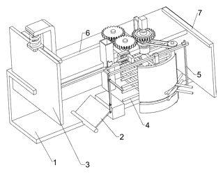
The patent describes a box-shaped mousetrap that combines a mechanical door-closing trigger with an automated internal sorting system.
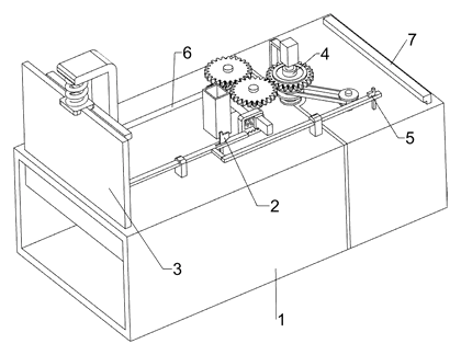
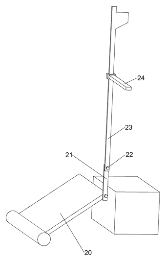
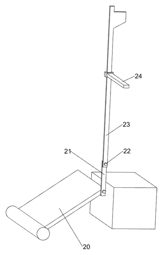
- Entry and Trigger: The device features a box body (1) with an entrance. A pedal (20) located on the inner bottom wall is connected to a movable rod (21). When a mouse steps on the pedal, it activates the first sliding rod (23).
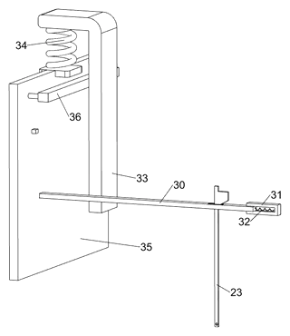
- Door Closure: The movement of the first sliding rod (23) drives the second sliding rod (30), which interacts with a spring-loaded sliding door (35). As the rod moves, it compresses the first spring (32) and releases the latch holding the door open. The second spring (34) then forces the sliding door (35) down, closing the entrance and trapping the mouse inside the left section of the box.
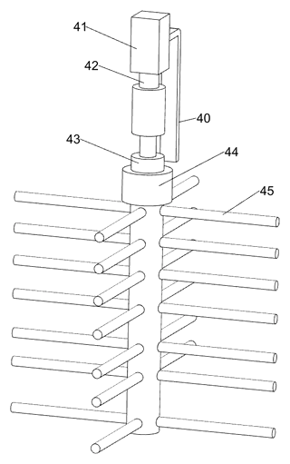
- Isolation Rotation: Once the door is closed, a motor (41) starts. It drives a second rotating shaft (42) and a fixed column (43) equipped with first stop rods (45). These rods rotate to gently push the trapped mouse toward the right side of the box, separating it from the entry point.
- Reset Mechanism: After isolation, a complex gear and spring system (the return mechanism) engages. Bevel gears and torsion springs reverse the motion of the rods, lifting the sliding door back to its open position and resetting the pedal and locking blocks for the next capture cycle.
- Disposal: A removable baffle (7) on the side of the box can be slid upward to access the isolated compartment, allowing the user to dispose of the rodent without touching the interior mechanisms.
Who it is for
- Pest Control Service Providers: Companies needing durable, reusable traps that reduce labor time per unit compared to single-use snap traps.
- Home Appliance Brands: Manufacturers looking to expand their product lines into smart or automated home maintenance tools.
- Retailers of Garden Supplies: Stores selling outdoor storage solutions where rodent prevention is critical for protecting goods.
- Industrial Facility Managers: Warehouses requiring humane or hygienic methods to manage rodent populations near food storage or packaging areas.
How it works
The main parts
| No. | Part | What it does |
|---|---|---|
| 1 | Box Body | Main housing containing all mechanisms. |
| 20, 21 | Pedal and Movable Rod | Detects mouse weight and initiates action. |
| 23, 30 | Sliding Rods | Transfer motion from the pedal to the door lock. |
| 35, 36 | Sliding Door and Handle | Closes the entrance to trap the mouse. |
| 32, 34 | Springs | Provide tension for locking and power for door closure/reset. |
| 41, 42 | Motor and Shaft | Drives the rotating column for isolation. |
| 43, 45 | Fixed Column and Stop Rods | Rotate to push the mouse to the disposal side. |
| 60-65 | Gear Set | Full gears and bevel gears enable the automatic reset sequence. |
| 7 | Baffle | Removable cover for accessing trapped mice. |
Operating Steps
- Detection: The mouse enters the box and steps on the pedal (20).
- Latching Release: The pedal movement shifts the sliding rods (23, 30), releasing the lock on the sliding door (35).
- Capture: The spring (34) snaps the door shut, trapping the mouse.
- Isolation: The motor (41) turns the column (43), moving the mouse to the right side.
- Reset: The gear train (60-65) reverses the rod positions, opening the door and preparing the trap for the next use.
Applications
Residential Kitchens and Pantries
Ideal for homes where hygiene is paramount. The enclosed design prevents blood or fur from scattering, unlike snap traps. Users can dispose of the rodent via the side baffle without seeing the animal directly, reducing psychological discomfort.
Warehouse and Storage Facilities
Suitable for large spaces where multiple traps are deployed. The auto-reset feature means staff do not need to check and re-arm each trap individually after every capture, saving maintenance time. The robust box structure withstands accidental bumps in high-traffic aisles.
Agricultural Outbuildings
Effective in barns or sheds where dust and debris might clog simpler mechanisms. The motorized rotation helps clear the capture zone, ensuring the trap remains functional even in less sterile environments. The enclosed nature protects bait from non-target animals like birds or larger mammals.
Retail Display Units
Can be placed behind counters or in stockrooms of grocery stores. The quiet operation of the spring-loaded door (compared to loud snap traps) avoids startling customers or employees. Its compact shape fits easily under shelves or in corners without obstructing workflow.
Where it is less suitable
- Extremely High Humidity/Water Exposure: While electronics are protected, prolonged immersion or heavy rain could compromise the motor and bearings unless additional sealing is applied in production.
- Very Small Entry Points: The box size may be too large for tight gaps where rats squeeze through, requiring placement in more open areas.
- Silent Operation Requirements: The motor and gear noise, though likely low, may be disruptive in bedrooms or libraries compared to silent snap traps.
Patent & Production
At a glance
| Patent number | CN112586483B (application CN202011385934) |
| Type | China invention patent (发明专利) - protects product structure and method |
| Original title | A box-shaped mousetrap (一种箱形捕鼠设备) |
| Patent owner | Shenzhen Ruilixing Environmental Service Co ltd |
| Inventors | Bai Fulou |
| Filing date | 2020-12-02 |
| Grant date | 2023-06-13 |
| Status (China) | In force - valid until at most 2040-12-02 (if annual fees are paid) |
| Patent family | Public record shows Chinese filings only - no US, European, Japanese, PCT or other filings listed |
| Cited by | 0 later documents |
| Source | Google Patents (search for CN112586483B) |
What the claims cover, in plain language
Claim 1 - defines a box-shaped mousetrap comprising a box body, a trigger mechanism, a door closing mechanism, and a revolving door (rotating column). The trigger uses a pedal connected to rods that release a spring-loaded sliding door. Upon capture, a motor drives a rotating column with stop rods to move the mouse to one side.
Claim 2 - adds a rotation mechanism involving a rotary column, transmission assembly, and third slide bar to coordinate the movement of the door and the rotating column.
Claim 3 - details the return (reset) mechanism. It uses full gears, bevel gears, torsion springs, and movable blocks to automatically reverse the motion, reopening the door and resetting the locking components after the mouse is isolated.
Claim 4 - specifies a baffle plate on the side of the box for accessing and removing trapped mice.
Claim 5 - states that the first stop rods on the rotating column are cylindrical.
This is a simplified reading for orientation only. The legal scope is defined by the exact claim wording in the official Chinese document.
What this means for US production
This patent was filed in China and is currently in force. The public record shows no US or other foreign counterpart. Making or selling this specific design in China requires the owner’s permission. In the US, the patent does not restrict production because there is no US patent covering this exact configuration.
Two points to settle early:
- Other patents may exist. Pest control devices are a highly competitive field with numerous existing US patents covering various trigger mechanisms, electric shock traps, and containment designs. A freedom-to-operate (FTO) review is essential to ensure this specific combination of motorized rotation and gear-based reset does not infringe on broader utility patents held by major US manufacturers.
- Electrical Safety Standards. Since the device contains a motor and potentially battery-powered components, it must meet strict US electrical safety standards, which differ significantly from Chinese GB standards.
Customization and manufacturing
What can be customized
| Area | Options |
|---|---|
| Material | ABS plastic, polypropylene, or coated steel for durability |
| Power Source | AA batteries, rechargeable lithium-ion pack, or USB-C input |
| Dimensions | Scale the box body to fit standard warehouse pallet gaps or residential corners |
| Sensors | Replace mechanical pedal with infrared proximity sensor for quieter triggering |
| Finish | Matte black, white, or camouflage patterns for aesthetic blending |
| Capacity | Adjust internal volume to handle larger rodents (rats vs. mice) |
Things to plan for (US market)
- UL/ETL Listing: Required for any electrical product sold in the US. The motor and battery management system must pass safety tests for overheating and short circuits.
- FCC Part 15: If wireless connectivity (Bluetooth/Wi-Fi) is added for app control, FCC certification is mandatory. Even simple motors may emit minor interference; shielding may be needed.
- CPSC Guidelines: Ensure no small parts detach that could pose a choking hazard, especially if marketed as household items accessible to children.
- Battery Compliance: UN 38.3 testing for shipping lithium batteries; labeling requirements for battery content.
How a project runs
- Inquiry - Define target market (residential/commercial), power preference, and quantity.
- Design - Adapt CAD models for injection molding tolerances and motor mounting.
- Prototype - Create functional samples using 3D-printed parts and off-the-shelf motors to test the reset logic.
- Pilot Run - Produce small batches to verify gear alignment and door smoothness.
- Production - Tooling for plastic shells, assembly of electronics, final QC.
Quantities & timeline
Injection molds for the box shell and internal frames will take 6-8 weeks to fabricate. Motor sourcing and electronic board procurement add lead time. Testing cycles for the mechanical reset mechanism are critical to prevent jamming. Send us your material preferences, power specs, estimated quantity, and target price and we will reply with options.
Production notes
Tooling and process
UV-stabilized injection molding is likely required for the outer shell if used outdoors, to prevent brittleness. Internal gears and sliders typically use POM or nylon for low friction. Motor assembly involves securing the DC motor to the frame with screws or snap-fit mounts.
Cost drivers
Precision mold tooling for the interlocking gear systems is likely a primary cost driver. UV grade resins increase material costs. Corrosion protection for metal shafts and springs adds processing expenses. Packaging volume affects freight costs due to the bulky box shape.
Prototyping path
Prototypes typically start with 3D-printed parts for the structural frame to validate dimensions. Use a coated tube sample for initial shaft testing. Conduct a functional sample build with real motors to test the reset timing. Proceed to tooling only after successful UV and spray tests on surface finishes.
What we would change before tooling
We would likely consider replacing the complex bevel gear set with a simpler cam mechanism if the reset reliability proves difficult to tune. Reinforce hinge bosses and pivot points, as these are high-stress areas prone to wear. Increase wall thickness in joint designs to prevent cracking during assembly.
Common failure points
Shaft and bearing alignment is critical; misalignment causes gear jamming. Spring fatigue and rate consistency can lead to door closure failures. Water ingress in electronics is a risk if seals degrade. Weld rust may occur on metal frames if coating is imperfect. Hinge boss and pivot wear will eventually loosen the door mechanism.
Patent drawings
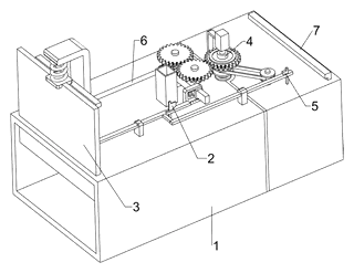
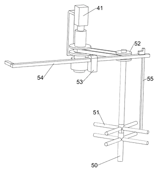
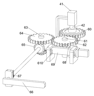
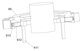
Drawings reproduced from the public patent document for reference.
Frequently asked questions
How does the trap reset itself?
After a mouse is caught and moved to the side by the rotating column, a system of gears, springs, and cams reverses the motion of the sliding rods. This lifts the door back to the open position and locks the mechanism ready for the next entry, without manual intervention.
What powers the motor?
The patent describes a motor but does not specify the voltage or battery type. For production, we typically recommend AA batteries for ease of replacement or a rechargeable lithium-ion pack for longer life. The choice depends on the target cost and usage frequency.
Is it safe for pets and children?
The entrance is enclosed within a box, reducing the risk of fingers getting caught compared to open snap traps. However, it is still a mechanical device. We recommend placing it in areas inaccessible to small children and ensuring the door closes firmly to prevent curious pets from interfering with the mechanism.
Can it catch rats as well as mice?
The current design is optimized for mice. To catch rats, the box body, door strength, and motor torque would need to be scaled up significantly. Rats exert much more force when trapped, which could damage the standard plastic gears or bend the thin rods described in the patent.
How noisy is the operation?
The mechanical clicking of the door closing is audible. The motor running the rotation is generally quiet, similar to a small toy motor. Noise levels can be reduced further by using rubber dampeners between the motor mount and the frame during production.
Does it work in wet or dirty environments?
The basic patent design does not mention waterproofing. For outdoor use, the electronics would need potting, and the shell would require gaskets. Dust accumulation in the gear mechanism could cause jamming over time, so regular cleaning is advised.
Can this design be made and sold in the US?
The patent is in force in China, but the public record shows no US counterpart. Therefore, this specific patent does not restrict manufacturing or sales in the United States. However, you must conduct a freedom-to-operate search to ensure no other US patents cover similar automated trapping technologies.
Are you affiliated with the patent owner?
No. IP2M is an independent design and manufacturing service working from the public patent document.
Request a quote
Click Request a Quote below to see our email address - copy it, or open your email app with a ready-made message. Please mention patent CN112586483B in the subject.
Helpful details to include:
- Your company and channel (pest control distributor, home appliance brand, garden supply retailer)
- Target market (indoor residential, commercial warehouse, outdoor agricultural)
- Power preference (battery type, voltage, or wired option)
- Material requirements (plastic type, color, finish)
- Estimated quantity and target price
- Timeline - when you would like samples and the first shipment
You can also reach us at (332) 203-9997.
Page editor: Daniel Chen, Product Research Editor · IP2M
Last updated November 5, 2026. If something on this page looks wrong, email [email protected] and we will check it against the patent.
Interested in building this?
Tell us your target market, quantity and timeline. We reply with options for prototyping, small-batch runs or volume production.
Send your inquiry to
Please put CN112586483B in the subject line and tell us your company, country, estimated quantity and timeline.
Prefer to talk? Call (332) 203-9997.
More product-ready patents
All Garden & Outdoor patents →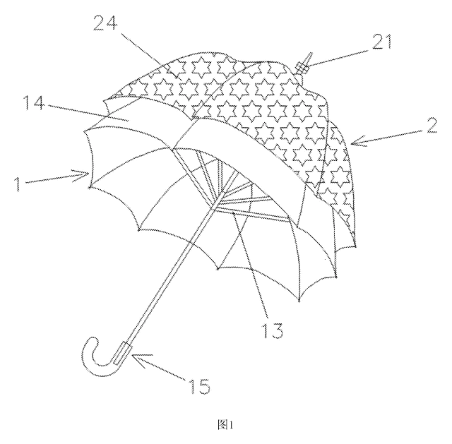
Garden & Outdoor
2-in-1 Parent & Child Umbrella
Full-size umbrella with a nested smaller umbrella on top - a rotating decorative layer that detaches into a kid-size umbrella.
Patent CN205611962U
Garden & Outdoor
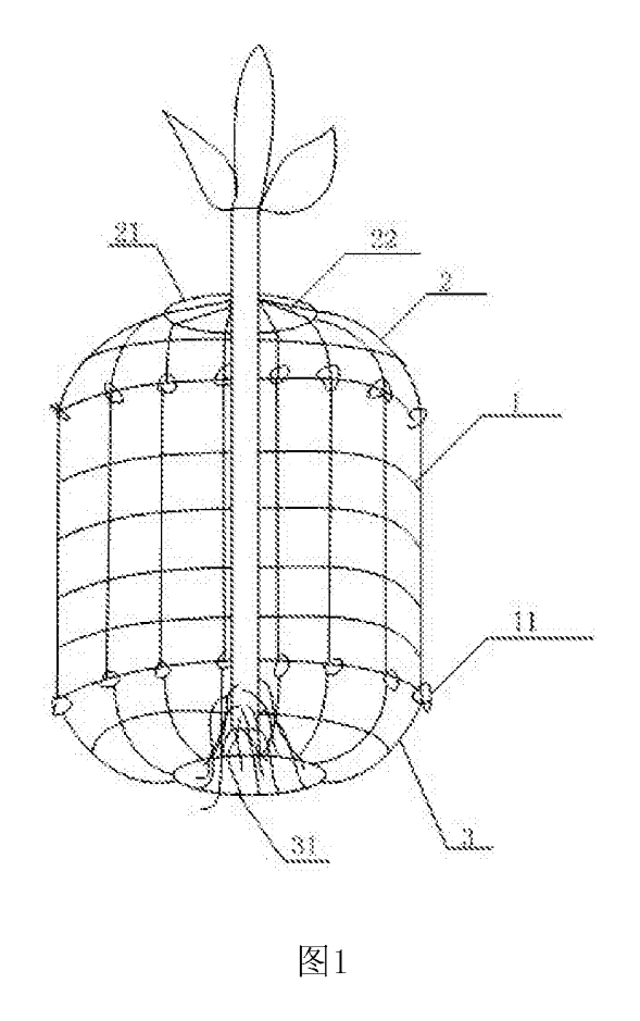
Wire-Mesh Tree Root & Trunk Guard Against Rodents
Three-part wire-mesh guard that protects the roots and lower trunk of young trees from burrowing and gnawing animals.
Patent CN206808261U
Garden & Outdoor
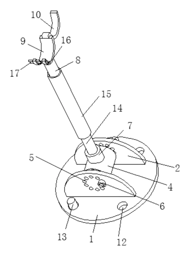
Adjustable-Angle Tree Support Prop
Tree prop with a pinned base, angle-locking hinge, twist-adjust tube and a locking trunk ring.
Patent CN208370491U
Garden & Outdoor
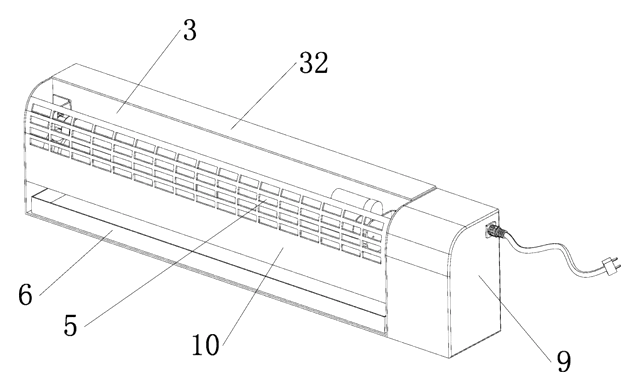
Self-Renewing Glue-Roller Mosquito Trap
UV insect trap with a glue roller that re-coats itself and scrapes the catch into a tray - no glue boards.
Patent CN217038569U
Garden & Outdoor
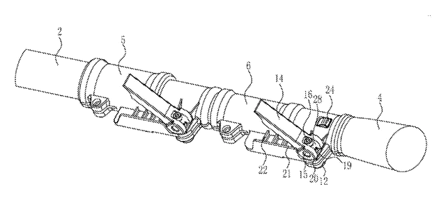
Cam-Lock Telescopic Pole for Garden Power Tools
Telescopic pole for garden power tools with cam-lever locks and a spring-button, tear-drop head socket.
Patent CN205812889U
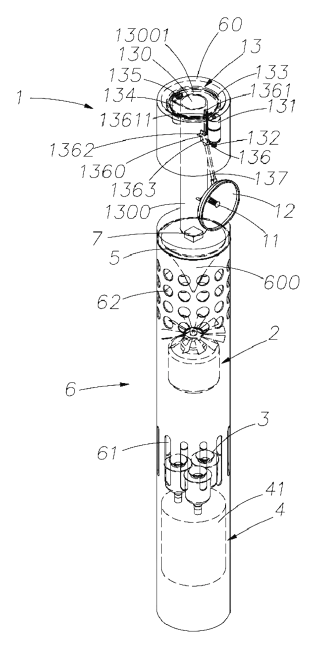
Garden & Outdoor
Mosquito Fan That Listens for Mosquitoes Before It Sprays
Fan with a scanning microphone dish that mists repellent only when it hears mosquitoes.
Patent CN208708542U
Browse by category
- Apparel & Accessories (39)
- Baby & Kids (26)
- Bags & Luggage (15)
- Bath & Personal Care (26)
- Car Accessories (21)
- Furniture, Bedding & Storage (21)
- Garden & Outdoor (29)
- Health & Wellness (12)
- Home, Kitchen & Cleaning (43)
- Lighting (20)
- Packaging & Containers (10)
- Pet Products (10)
- Phone & Camera Accessories (8)
- Retail Display (22)
- School, Office & Art (30)
- Sports & Recreation (39)
- Tools & Workshop (48)
- Toys & Games (20)
This page is based on the public patent document CN112586483B, assigned to Shenzhen Ruilixing Environmental Service Co ltd. IP2M is an independent manufacturing service and is not affiliated with, endorsed by or licensed by the patent owner. Images marked as concept renderings are illustrations, not photos of an existing product. Patent status information is provided for reference only and is not legal advice; confirm freedom to operate for your market before production. Full disclaimer.