
Patent CN113442984B
Updated November 8, 2026Spring-Loaded Luggage Trolley with Auto-Retaining Baffles for High-Speed Rail Transfer
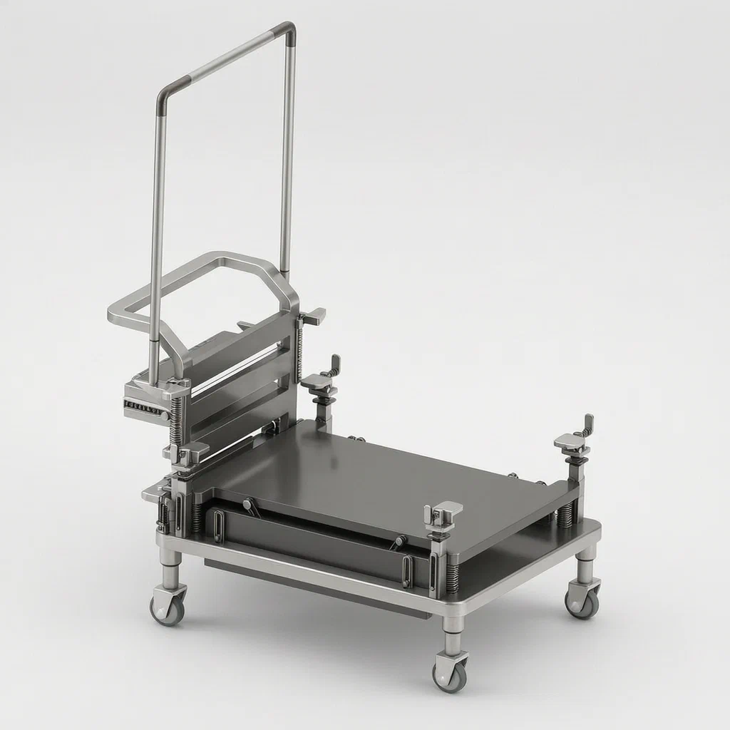
Standard airport carts rely on manual straps or open platforms, leaving heavy bags vulnerable to shifting or falling when navigating crowded train stations or uneven terrain. This patent describes a self-adjusting retention system. By placing luggage on the platform, the user’s own load activates the safety mechanism. Gravity pushes the platform down against four main springs. Through a series of rotating levers and sliding bars, this vertical motion is converted into horizontal movement, raising side panels that surround the bags. No buckles, no straps, and no extra effort are required to secure the load. The system resets instantly when the bag is lifted off.
- China invention patent - lapsed
- No filings outside China
- Travel & Logistics Equipment
- Steel tube forming, PP/ABS injection molding, fabric sewing
Splat! What let you down?
⬇️
Gravity-Activated Lock
The weight of the luggage itself pushes the platform down, triggering the baffle system.
🛡️
Auto-Retaining Baffles
Side panels rise automatically as the platform descends, enclosing bags without manual strapping.
🦶
Foot-Pedal Brake
Integrated brake blocks engage wheels via a pedal and linkage system for stationary stability.
📦
Sliding Storage Frame
Includes a dedicated sliding compartment for tickets, phones, or small personal items.
Bring this product to market
- ✓ Patent review Patent family and legal status reviewed in the relevant jurisdictions.
- 2 Product brief · now How it works, uses and options written up
- 3 Prototype First samples for buyers to review
- 4 Pilot run Small first batch for launch customers
- 5 Volume production Repeat orders at scale
Buyer interest
– of 100 buyers needed to start prototyping
One click, no sign-up. Each vote is one real visitor, and products with the most interest go to prototyping first.
Build team: no members yet. Need a partner, co-funding or skills to build this? Join and we introduce the team once it forms.
Patent Rights & Team Participation
Before joining a development team, participants should ensure they have the necessary rights or authorization to participate in the project.
Participation is generally appropriate where:
- You own the relevant patent rights or have obtained permission or a license from the rights holder.
- The relevant patent rights have expired or have been legally invalidated in the jurisdictions where the planned activities will take place.
- The planned development, manufacturing, and commercialization activities have been independently assessed and do not infringe applicable patent rights in the relevant jurisdictions.
Important: Being located outside a country where a patent is protected does not automatically exempt you from patent infringement risks. Patent rights may apply based on where development, manufacturing, use, sale, or import activities take place.
IP2M does not grant any patent license or authorization through team participation. Joining a project does not provide permission to use, manufacture, or commercialize patented technology.
The problem
In busy high-speed rail stations, travelers often manage multiple large suitcases on shared trolleys. Standard carts have flat, open platforms. When navigating crowds, ramps, or sudden stops, bags can slide off or tip over, creating hazards and requiring constant manual adjustment by the user. Traditional solutions involve elastic bands or netting, which require the user to stop, stretch the band, and hook it securely—a cumbersome process that many skip due to time pressure. Furthermore, securing these straps manually does not adapt dynamically to the changing center of gravity as bags are added or removed. There is a need for a passive, automatic retention system that engages solely through the act of loading the luggage, ensuring stability without user intervention.
The solution
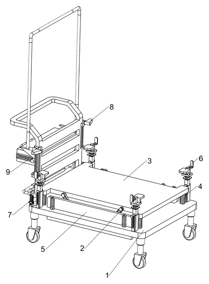
- A base (1) supports the entire structure, housing internal mechanisms and mounting points for wheels.
- A placement mechanism (2) sits atop the base. It includes a placement plate (3) connected to four first springs (4).
- When luggage is placed on the plate (3), its weight compresses the springs (4), pushing the plate downward.
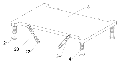
- This downward motion drives first support rods (21) and first slide bars (24) attached to the plate.
- These components interact with rotating rods (22) mounted on first rotating shafts (23) inside the base, converting vertical movement into rotational force.
- The rotation of the rods (22) pulls second slide bars (52) attached to baffles (51).
- As the second slide bars (52) move, they drag the baffles (51) upward along third slide bars (54) in first chutes (53).
- The result is that the side baffles (51) rise to enclose the luggage, preventing it from falling off.
- When the luggage is removed, the tension in the first springs (4) lifts the placement plate (3) back to its original position, causing the baffles (51) to lower automatically.
Who it is for
- Station Logistics Operators: Managing fleets of carts in high-traffic hubs where speed and safety are critical.
- Travel Gear Brands: Developing premium luggage accessories that offer hands-free security features.
- Hotel Concierge Services: Providing enhanced service for guests moving multiple bags between vehicles and elevators.
- Airport Retailers: Selling specialized carts that differentiate from standard metal utility trolleys.
How it works
The main parts
| No. | Part | What it does |
|---|---|---|
| 1 | Base | Structural foundation; houses shafts and chutes. |
| 2 | Placement Mechanism | Linkage system converting vertical load to lateral motion. |
| 3 | Placement Plate | The surface where luggage rests; moves vertically. |
| 4 | First Springs | Provide return force to lift the plate when empty. |
| 21 | First Support Rods | Guide the vertical movement of the plate. |
| 22 | Rotating Rods | Levers that pivot to drive the baffles. |
| 51 | Baffles | Side walls that rise to secure luggage. |
| 61 | Telescopic Rods | Adjustable height handles or locks (part of locking assembly). |
| 71 | Brake Blocks | Engage wheels to stop the cart. |
| 93 | Storage Frame | Sliding compartment for small items. |
Operating Steps
- Load Luggage: Place suitcases on the placement plate (3).
- Compression: The weight pushes the plate down, compressing the first springs (4).
- Linkage Activation: The descent moves the first slide bars (24), turning the rotating rods (22).
- Baffle Rise: The rotation pulls the second slide bars (52), lifting the baffles (51) up around the bags.
- Transport: Push the trolley; the bags are enclosed by the baffles.
- Unload: Lift the luggage off the plate.
- Reset: The first springs (4) expand, raising the plate (3) and lowering the baffles (51) back to the resting position.
Applications
High-Speed Rail Interchanges
Travelers transferring between trains often carry multiple heavy bags. The auto-raising baffles ensure that bags do not slide off while navigating crowded platforms or escalators, reducing the risk of dropped luggage disrupting station operations.
Airport Terminal Shuttles
In large airports, carts traverse long distances with varying speeds. The mechanical engagement prevents bags from tipping over during sharp turns or sudden stops, offering a safer alternative to strap-based carts that users frequently neglect to use.
Hotel Lobby Services
Concierge staff managing guest luggage benefit from the quick-load capability. Placing a bag automatically secures it, allowing staff to move quickly through tight elevator spaces without stopping to adjust restraints, improving service efficiency.
Cruise Port Transfers
Embarking and disembarking involves moving bags across gangways and shuttle buses. The integrated brake system allows the cart to be locked securely on inclines or docks, while the baffles protect bags from wind or accidental bumps.
Where it is less suitable
- Extremely Light Items: If the luggage weighs too little to compress the springs significantly, the baffles may not rise fully.
- Irregularly Shaped Cargo: Bags that are wider than the baffle travel range or oddly shaped may not fit within the enclosure area.
- Static Display Use: For retail displays where bags are never moved, the mechanical complexity adds cost without functional benefit compared to simple shelves.
Patent & Production
At a glance
| Patent number | CN113442984B (application CN202110786070) |
| Type | China invention patent - protects method and product structure |
| Original title | Multifunctional luggage trolley for high-speed rail transfer (一种高铁换乘用多功能行李推车) |
| Patent owner | Nanjing Xinsanrenhang Network Technology Co ltd |
| Inventors | Chen Lianxiang |
| Filing date | 2021-07-12 |
| Grant date | 2023-06-23 |
| Status (China) | Lapsed - terminated for non-payment of annual fees (recorded 2025-07-04) |
| Patent family | Public record shows Chinese filings only - no US, European, Japanese, PCT or other filings listed |
| Cited by | 0 later documents |
| Source | Google Patents (search for CN113442984B) |
What the claims cover, in plain language
Claim 1 defines a luggage trolley comprising a base (1) and a placement mechanism (2). Four first springs (4) connect a placement plate (3) to the mechanism. A shielding mechanism (5) is positioned to block luggage from falling. The placement mechanism uses first support rods (21), rotating rods (22), and first slide bars (24) linked to first rotating shafts (23). The shielding mechanism uses baffles (51) driven by second slide bars (52) and third slide bars (54) moving in first chutes (53). The claim specifies that downward movement of the plate causes the baffles to rise. The claim further details a locking assembly (6) with telescopic rods (61), wedge blocks (65), and lock blocks (67); a brake assembly (7) with brake blocks (71), connecting rods (72), pedals (74), and wedges (78); and a storage component (9) with a sliding frame (93) on fixed blocks (91).
This is a simplified reading for orientation only. The legal scope is defined by the exact claim wording in the official Chinese document.
What this means for US production
This patent was filed in China and has lapsed due to non-payment of fees, so it no longer restricts anyone in China either. The public record shows no US or other foreign counterpart.
Two points to settle early:
- Other patents may exist. Luggage carts and auto-locking mechanisms are common in consumer goods and industrial logistics. While this specific spring-linkage combination appears unique in this filing, broader patents covering “gravity-assisted retention” or “self-locking carts” may exist in the US. A freedom-to-operate (FTO) review is recommended before tooling.
- Mechanical Complexity. The integration of braking, locking, and auto-baffling increases part count. Simplifying the linkage while retaining the core function may be necessary for cost-effective mass production.
Customization and manufacturing
What can be customized
| Area | Options |
|---|---|
| Dimensions | Base size and handle height adjusted for different luggage sizes. |
| Material | Steel tube forming for frame; PP/ABS injection molding for plates and baffles. |
| Spring Rate | Stiffness of first springs adjusted based on expected minimum luggage weight. |
| Finish | Powder coating for steel; matte or glossy plastic finishes. |
| Features | Optional removal of brake or storage module for simpler versions. |
Things to plan for (US market)
- CPSC Safety Standards: General requirements for children’s products if marketed near kids, but primarily relevant here is ANSI/ASTM F2057 for furniture stability (tip-over risks) and general mechanical safety standards regarding pinch points.
- Proposition 65: California warning labels may be required depending on materials used (e.g., certain plastics or metal coatings).
- Packaging: Compliance with ISTA testing for shipping durability.
How a project runs
- Inquiry - Define target load capacity, dimensions, and desired features (brakes/storage).
- Design - Finalize linkage geometry, select spring rates, and create CAD models.
- Prototype - 3D-printed fit samples to verify baffle movement and spring compression.
- Pilot Run - Assemble small batch using molded parts and formed tubes; conduct load and cycle tests.
- Production - Mass produce molds, form tubes, assemble, and package.
Quantities & timeline
Injection molds for the placement plate, baffles, and connectors require significant lead time. Steel tube bending fixtures must be custom-built. Assembly involves precise alignment of slide bars and rotating shafts. Send us your target dimensions, load capacity, material preferences, quantity and target price and we will reply with options.
Production notes
Tooling and process
Likely requires steel tube forming dies for the base frame and precision injection molds for the plastic placement plate, baffles, and connector housings. Fabric sewing may be needed if soft liners are added to the storage frame.
Cost drivers
Part count is typically high due to the multi-spring and linkage system, driving assembly costs. Material certification for plastics and metals adds overhead. Rounded edges and tooling adjustments for safety testing increase mold complexity.
Prototyping path
We typically start with 3D-printed fit samples to validate the kinematic chain. Proceed to material certificates and small-parts/pinch tests. Load samples should verify spring fatigue resistance before final tooling.
What we would change before tooling
We would simplify the locking assembly if not strictly required, reducing part count. We might integrate the storage frame directly into the base to eliminate separate sliding rails.
Common failure points
Spring fatigue and rate consistency are critical; weak springs fail to reset the baffles. Pinch points between moving slide bars and chutes pose safety risks. Hinge boss and pivot wear may loosen the linkage over time.
Patent drawings
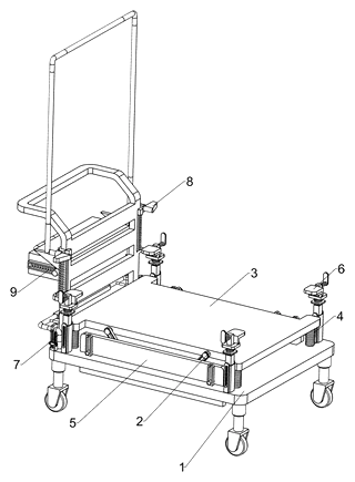
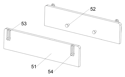
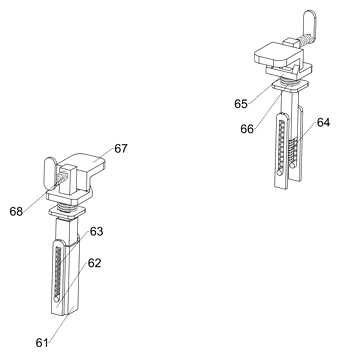
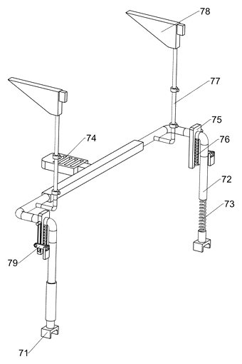
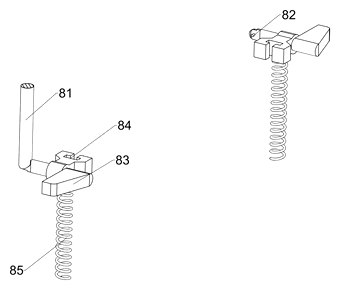
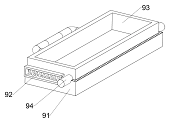
Drawings reproduced from the public patent document for reference.
Frequently asked questions
How does the baffle system actually work?
It is purely mechanical and passive. When you place a suitcase on the top plate, the weight pushes the plate down against springs. This downward movement rotates internal levers, which pull the side panels (baffles) up to surround the bag. When you take the bag off, the springs push the plate back up, and the panels lower automatically.
Do I need to strap my bags in?
No. According to the patent, the baffles rise to enclose the luggage, preventing it from falling off during transport. However, for very tall or unstable loads, additional care may still be needed as the baffles only cover the sides.
What happens if the luggage is too light?
If the item is lighter than the spring preload, the plate may not descend enough to trigger the full baffle movement. Design specifications for minimum weight activation are set in engineering and confirmed on prototypes.
Is the brake system effective on slopes?
The patent describes a foot-pedal brake that engages blocks against the wheels. Effectiveness depends on the friction material and wheel diameter, which are determined during the design phase and verified through slope testing.
Can the storage frame hold heavy items?
The storage frame is a sliding compartment intended for small items like tickets or phones. Its load capacity is limited by the slide mechanism and is specified in the final product design.
How durable are the springs?
Springs are subject to fatigue over time. The patent uses multiple springs to distribute the load. Lifespan depends on the spring material and cycle count, typically validated through accelerated life testing during prototyping.
Can this design be made and sold in the US?
The patent was filed in China and has lapsed due to non-payment of fees, and the public record shows no US counterpart, so it does not restrict the design in the US or in China. However, other US patents may cover similar auto-locking cart concepts, so we recommend a freedom-to-operate check before volume production.
Are you affiliated with the patent owner?
No. IP2M is an independent design and manufacturing service working from the public patent document.
Request a quote
Click Request a Quote below to see our email address - copy it, or open your email app with a ready-made message. Please mention patent CN113442984B in the subject.
Helpful details to include:
- Your company and channel (station operator, travel gear brand, hotel supplier)
- Target load capacity and minimum activation weight
- Dimensions (base size, handle height)
- Materials preference (steel/aluminum frame, plastic types)
- Estimated quantity and target price
- Timeline - when you would like samples and the first shipment
You can also reach us at (332) 203-9997.
Page editor: Emily Zhang, Product Editor · IP2M
Last updated November 8, 2026. If something on this page looks wrong, email [email protected] and we will check it against the patent.
Interested in building this?
Tell us your target market, quantity and timeline. We reply with options for prototyping, small-batch runs or volume production.
Send your inquiry to
Please put CN113442984B in the subject line and tell us your company, country, estimated quantity and timeline.
Prefer to talk? Call (332) 203-9997.
More product-ready patents
All Baby & Kids patents →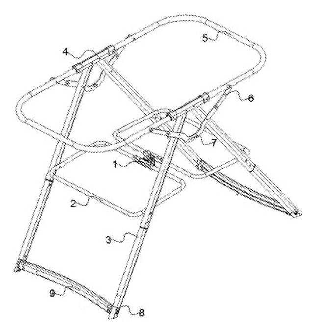
Baby & Kids
Portable Folding Rocking Bassinet Frame
Rocking bassinet frame that folds flat: telescopic hub, folding rails, two-part legs, curved rockers.
Patent CN206910143U
Baby & Kids
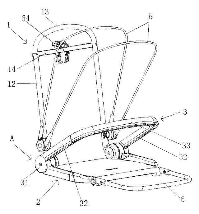
Stroller Seat with Linked Fold-Away Armrest
Stroller seat whose armrest unlocks and folds automatically when the backrest is folded forward.
Patent CN206856772U
Baby & Kids
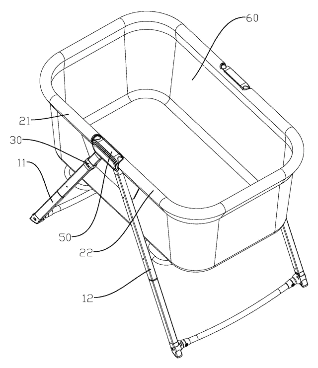
One-Motion Folding Baby Crib with Linked Frame
Portable baby crib whose top rails fold down automatically as the A-frame legs are closed.
Patent CN207202585U
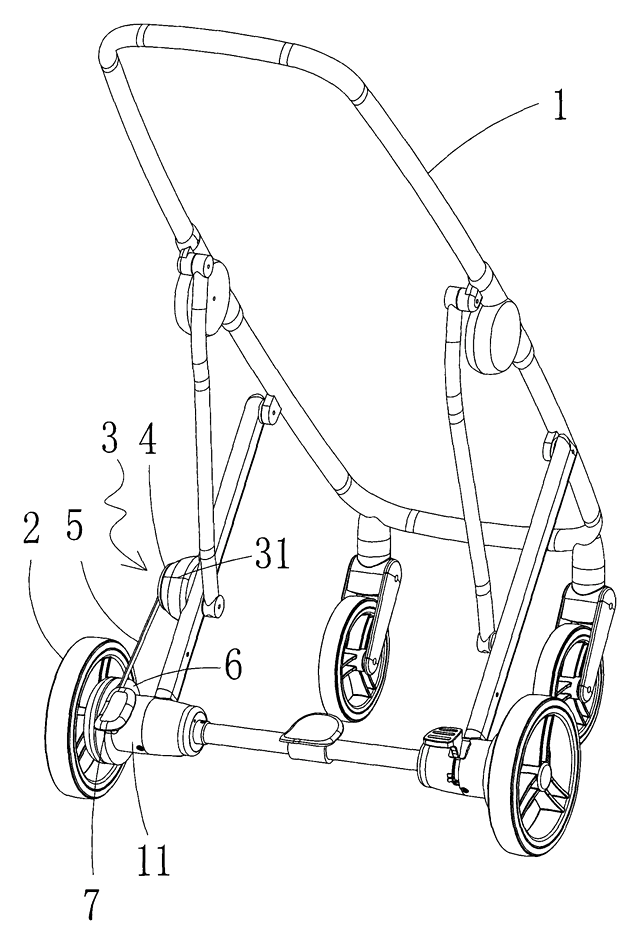
Baby & Kids
Motorized Rocking Stroller That Rocks by Turning Its Wheels
Baby rocker or stroller whose motor turns the wheels back and forth; a clutch switches to pushing.
Patent CN208119238U
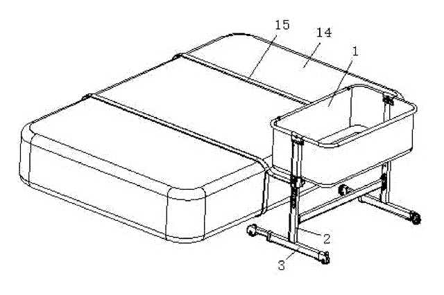
Baby & Kids
Bedside Crib Base with Spring-Loaded Telescoping Caster Legs
Bedside crib feet with spring-loaded sliding casters: wide when alone, short to sit flush at the bed.
Patent CN207168269U
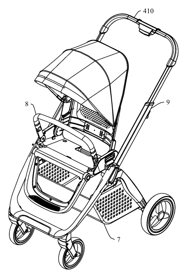
Baby & Kids
Compact-Fold Stroller with a Four-Bar Side Frame and Telescoping Handle
Stroller with four-bar side frames: handle and rear leg fold onto the front leg, handle telescopes.
Patent CN213799844U
Browse by category
- Apparel & Accessories (51)
- Baby & Kids (30)
- Bags & Luggage (17)
- Bath & Personal Care (33)
- Car Accessories (27)
- Furniture, Bedding & Storage (25)
- Garden & Outdoor (34)
- Health & Wellness (15)
- Home, Kitchen & Cleaning (52)
- Lighting (25)
- Packaging & Containers (13)
- Pet Products (12)
- Phone & Camera Accessories (10)
- Retail Display (27)
- School, Office & Art (38)
- Sports & Recreation (49)
- Tools & Workshop (57)
- Toys & Games (24)
This page is based on the public patent document CN113442984B, assigned to Nanjing Xinsanrenhang Network Technology Co ltd. IP2M is an independent manufacturing service and is not affiliated with, endorsed by or licensed by the patent owner. Images marked as concept renderings are illustrations, not photos of an existing product. Patent status information is provided for reference only and is not legal advice; confirm freedom to operate for your market before production. Full disclaimer.