
Patent CN113460518B
Updated October 27, 2026Hinge Device for Folding Containers with Integrated Twistlock Hole
Folding containers save space during return shipping, but their hinges must handle heavy loads when erected. Standard hinges often lack a direct mounting point for twistlocks or require extra cutouts for visual checks, which weakens the metal. This hinge design solves both issues by placing a twistlock hole directly on the outer end face of the movable hinge, right next to the movable locking hole. When the container is folded, this twistlock hole lines up vertically with the bottom hole of the container's corner fitting, allowing a twistlock to be installed for lifting or stacking. Because the locking hole and twistlock hole are close together near the edge, the force arm that limits the locking pin from rotating is increased. Furthermore, the movable locking hole doubles as an observation port, letting workers see if the twistlock is fully engaged without drilling another hole in the hinge plate.
- China invention patent - in force
- No filings outside China
- Containers & Packaging
- Steel fabrication, heavy-duty transport
Splat! What let you down?
🔗
Integrated twistlock hole
The movable hinge features a twistlock hole on its outer face for connecting a twistlock during installation.
👁️
Built-in observation
The movable locking hole doubles as a viewing port to check twistlock engagement without extra cutouts.
💪
Increased force arm
Placing the locking hole and twistlock hole near the edge improves the capacity to limit locking pin rotation torque.
📐
Vertical alignment
When folded, the twistlock hole aligns in the same vertical direction as the bottom hole of the corner fitting.
Bring this product to market
- ✓ Patent vetted China-only family and legal status checked
- 2 Product brief · now How it works, uses and options written up
- 3 Prototype First samples for buyers to review
- 4 Pilot run Small first batch for launch customers
- 5 Volume production Repeat orders at scale
Buyer interest
– of 100 buyers needed to start prototyping
One click, no sign-up. Each vote is one real visitor, and products with the most interest go to prototyping first.
Build team: no members yet. Need a partner, co-funding or skills to build this? Join and we introduce the team once it forms.
The problem
Folding containers are used to reduce empty shipping volume, but their hinges endure significant stress when the end walls are raised for cargo loading. If the hinge structure is compromised by too many cutouts, the overall strength drops. Operators also need to attach twistlocks for lifting and securing, which usually requires separate brackets or holes. Additionally, verifying that a twistlock is properly engaged often means adding dedicated observation holes, further weakening the hinge plate and complicating manufacturing.
The solution
This hinge device addresses these structural and operational challenges through specific geometric arrangements:
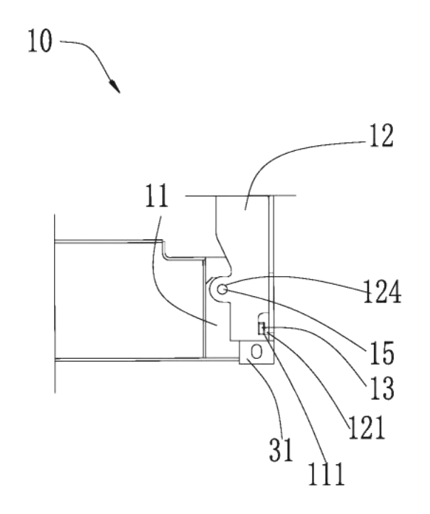
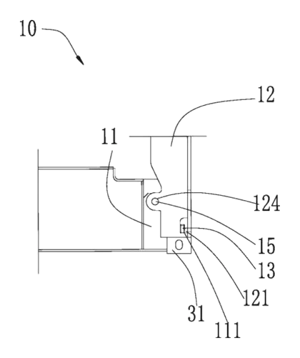
- A fixed hinge is arranged on the underframe of the folding container, featuring a fixed locking hole positioned close to its edge.
- A movable hinge is mounted on the end wall and rotatably connected to the fixed hinge, allowing it to pivot between a first position (folded) and a second position (upright).
- The movable hinge has a movable locking hole, also placed close to its edge. When rotated to the second position, this hole aligns with the fixed locking hole.
- A locking pin penetrates both holes to lock the movable hinge relative to the fixed hinge when the container is open.
- The outer end face of the movable hinge includes a twistlock hole located close to the movable locking hole. This hole accepts a linked twistlock.
- When the movable hinge is in the first position, the twistlock hole and the bottom hole of the container’s corner fitting are in the same vertical direction.
- The movable locking hole simultaneously functions as an observation port, allowing personnel to look through it and confirm whether the twistlock inside the twistlock hole is locked.
Who it is for
- Intermodal equipment manufacturers building collapsible freight containers who need robust hinges that integrate twistlock mounting points without sacrificing steel integrity.
- Logistics and shipping companies operating return-trip fleets where containers are folded flat; they benefit from faster twistlock verification during loading operations.
- Military and expeditionary logistics units that deploy temporary storage or transport boxes requiring rapid assembly and verified secure connections in the field.
- Modular construction suppliers using foldable steel frames for site offices or storage, needing reliable pivoting joints that support standard container hardware.
How it works
The main parts
| No. | Part | What it does |
|---|---|---|
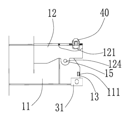
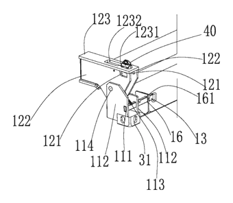
| 11 | Fixed hinge | Mounted on the underframe; holds the fixed locking hole. |
| 12 | Movable hinge | Attached to the end wall; rotates between folded and upright positions. |
| 111 | Fixed locking hole | Located near the edge of the fixed hinge to receive the locking pin. |
| 121 | Movable locking hole | Located near the edge of the movable hinge; aligns with the fixed hole and acts as an observation port. |
| 13 | Locking pin | Passes through both locking holes to fix the hinge in the second position. |
| 1231 | Twistlock hole | On the outer end face of the movable hinge, close to the movable locking hole, for installing a twistlock. |
| 123 | Connecting portion | Links the movable portions of the hinge; contains the twistlock hole and a receiving hole. |
| 1232 | Receiving hole | Formed on one side of the twistlock hole to house the twistlock. |
Operating steps
- Unfolding: The end wall is pivoted from the first position (folded onto the base frame) to the second position (perpendicular to the base frame). The patent describes an angle of rotation of 90 degrees.
- Locking: As the movable hinge reaches the second position, the movable locking hole aligns with the fixed locking hole. The locking pin is inserted through both holes to hold the end wall rigidly in place.
- Folding for transport: To collapse the container, the locking pin is removed, and the end wall is rotated back to the first position.
- Twistlock installation: In the first position, the twistlock hole aligns vertically with the bottom hole of the corner fitting. A twistlock is inserted into the receiving hole and twistlock hole.
- Verification: An operator looks through the movable locking hole to visually confirm that the twistlock is fully engaged, avoiding missed operations.
Applications
Intermodal freight shipping
Shipping lines use folding containers to reposition empty units efficiently. During loading, the hinges must withstand dynamic forces. The integrated twistlock hole allows standard securing devices to be attached directly to the hinge area, streamlining the process.
Port terminal operations
Terminal workers need to stack and lift folded containers quickly. Because the twistlock hole aligns vertically with the corner fitting’s bottom hole when folded, cranes can engage the twistlocks without awkward angles. The observation port lets ground crews verify engagement before a lift begins.
Military deployment logistics
Armed forces rely on collapsible containers for rapid base setup. Personnel in the field need simple, fail-safe mechanisms. The dual-purpose locking hole eliminates the need for separate inspection tools, ensuring the end walls are securely pinned before cargo is loaded.
Temporary site storage
Construction sites use foldable steel boxes for tool and material storage. These boxes are assembled and disassembled frequently. The rectangular or circular cross-section options for the locking pin and holes allow manufacturers to tailor the joint to the expected load.
Where it is less suitable
- Standard dry van containers - permanent, non-folding containers do not require 90-degree pivoting hinges and use fixed corner posts instead.
- Lightweight plastic bins - this hinge arrangement is designed for heavy steel underframes and end walls; plastic containers use molded snap-hinges.
- Tank containers - cylindrical liquid tanks lack the flat end walls required for this specific hinge geometry.
Frequently asked questions
What is the main advantage of this hinge design?
It combines the twistlock mounting hole and the locking hole on the same movable hinge plate. Placing them close together near the edge increases the force arm that limits the locking pin from rotating under load. It also removes the need for a separate observation hole, keeping the steel stronger.
How does the observation function work?
The movable locking hole is intentionally made larger than the locking pin (for example, about 110mm by 55mm compared to a 60mm by 30mm pin). When the container is folded and a twistlock is installed, operators can look through this extra space in the movable locking hole to visually confirm that the twistlock is properly engaged.
Can the locking pin be round instead of rectangular?
Yes. While some claims describe a rectangular cross section to prevent rotation, the patent also covers an embodiment where the fixed locking hole, the movable locking hole, and the locking pin are all circular in cross section. The choice depends on the manufacturer’s design preference.
How far does the end wall rotate?
The patent describes the movable hinge rotating exactly 90 degrees from the first position (folded flat against the base frame) to the second position (perpendicular to the base frame, ready for cargo loading).
Does the twistlock hole fit standard container twistlocks?
The twistlock hole is positioned so that when the hinge is folded, it aligns in the same vertical direction as the bottom hole of the container’s corner fitting. The receiving hole on the connecting portion houses the twistlock. Exact dimensions are set in design and confirmed on prototypes to match the specific twistlock model you use.
What materials are used for the hinges?
The patent text focuses on the geometry and mechanical arrangement rather than specifying steel grades. Material selection, plate thickness, and surface treatments are to be confirmed in design based on the container’s payload and environmental exposure.
Can this design be made and sold in the US?
The patent was filed only in China and is currently in force there until at most 2041-08-09 (if annual fees are paid). It has no US counterpart, so it does not restrict making or selling the design in the US. However, other companies hold US patents citing this technology in the folding container field. We strongly recommend a freedom-to-operate review before production.
Are you affiliated with the patent owner?
No. IP2M is an independent design and manufacturing service working from the public patent document.
Request a quote
Click Request a Quote below to see our email address - copy it, or open your email app with a ready-made message. Please mention patent CN113460518B in the subject.
Helpful details to include:
- Your company and channel (container manufacturer, logistics fleet operator, modular builder)
- Container dimensions and target payload
- Locking pin preference (rectangular or circular cross section)
- Twistlock model you intend to use
- Material and finish requirements (e.g., steel grade, marine paint)
- Estimated quantity and target price
- Timeline - when you would like samples and the first shipment
You can also reach us at (332) 203-9997.
Explore this product
Interested in building this?
Tell us your target market, quantity and timeline. We reply with options for prototyping, small-batch runs or volume production.
Send your inquiry to
Please put CN113460518B in the subject line and tell us your company, country, estimated quantity and timeline.
Prefer to talk? Call (332) 203-9997.
More product-ready patents
All Packaging & Containers patents →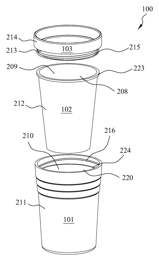
Packaging & Containers
Rigid Shell Container with Removable Silicone Liner
Cup or food box with a rigid outer shell and a removable, leak-tight silicone liner.
Patent CN212638395U
Packaging & Containers
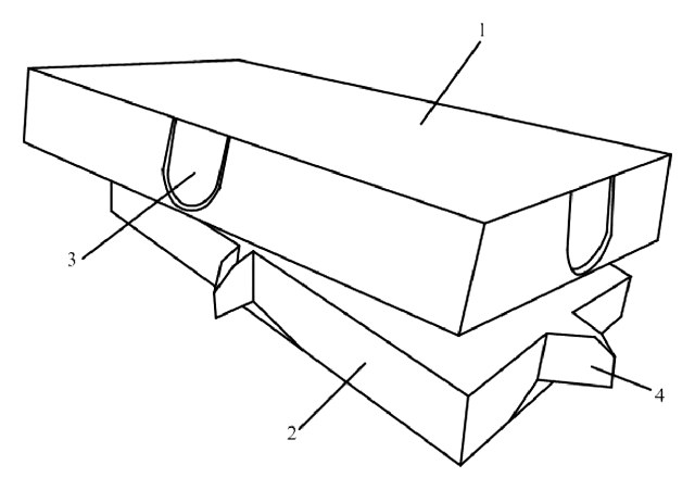
Child-Resistant Paperboard Medicine Box with Three-Point Opening
Paperboard medicine box that opens only when press points on three sides are pushed together.
Patent CN107117365B
Packaging & Containers
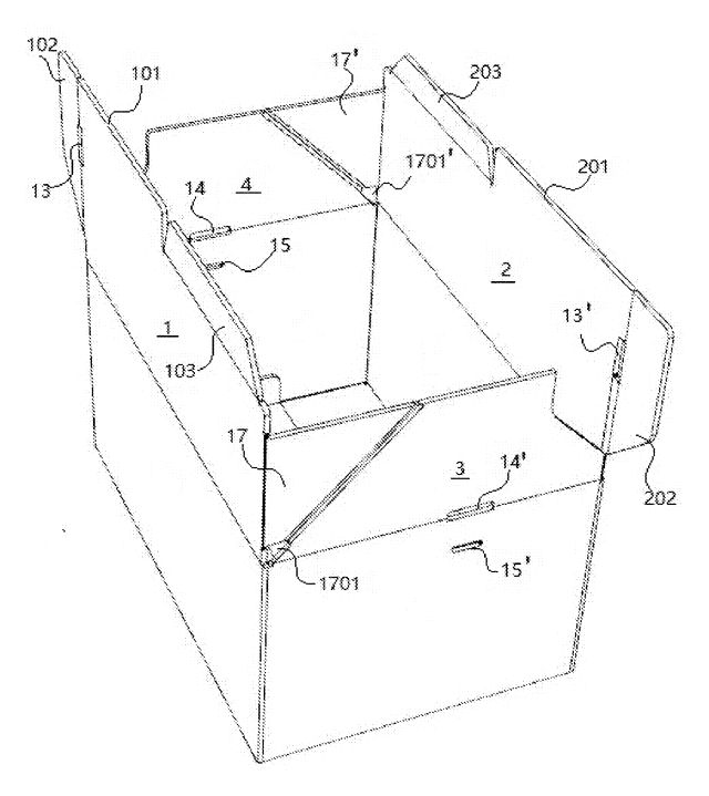
Tape-Free Reusable Shipping Box with Zigzag Interlocking Flaps
Reusable carton closed without tape: zigzag flaps interlock, tabs tuck in, a U-clip locks the lid.
Patent CN207242262U
Packaging & Containers
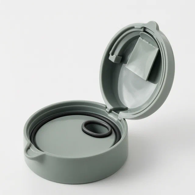
Cylindrical Plastic Bottle Cap with Built-In Soup Ladle
Plastic bottle cap storing a soup ladle inside, with a flip-top lid and inner sealing closure.
Patent CN106144192B
Packaging & Containers
Insulated Food Packaging Box with Detachable Liner and Self-Heating Cavity
Detachable insulated food box with a sealed cavity for a self-heating sheet and a temperature sticker.
Patent CN108372980B
Lighting
U-Shaped LED Fluorescent Lamp with a Soft Substrate and Rear Support Frame
U-shaped LED lamp: a soft substrate bends around a positioning column in the support frame.
Patent CN205447315U
Browse by category
- Apparel & Accessories (22)
- Baby & Kids (16)
- Bags & Luggage (9)
- Bath & Personal Care (16)
- Car Accessories (10)
- Furniture, Bedding & Storage (12)
- Garden & Outdoor (18)
- Health & Wellness (8)
- Home, Kitchen & Cleaning (24)
- Lighting (12)
- Packaging & Containers (6)
- Pet Products (6)
- Phone & Camera Accessories (4)
- Retail Display (13)
- School, Office & Art (19)
- Sports & Recreation (25)
- Tools & Workshop (27)
- Toys & Games (12)
This page is based on the public patent document CN113460518B, assigned to Guangdong Xinhui CIMC Special Transportation Equipment Co Ltd. IP2M is an independent manufacturing service and is not affiliated with, endorsed by or licensed by the patent owner. Images marked as concept renderings are illustrations, not photos of an existing product. Patent status information is provided for reference only and is not legal advice; confirm freedom to operate for your market before production. Full disclaimer.