At a glance
| Patent number | CN113460518B (application CN202110909062) |
| Type | China invention patent (发明专利) - protects product shape, structure and methods |
| Original title | Hinge device for folding container and folding container (折叠式集装箱用铰链装置及折叠式集装箱) |
| Patent owner | Guangdong Xinhui CIMC Special Transportation Equipment Co Ltd |
| Inventors | Li Shengqi, Zhao Jiangang |
| Filing date | 2021-08-09 |
| Grant date | 2022-12-30 |
| Status (China) | In force in China until at most 2041-08-09 (if annual fees are paid) |
| Patent family | Chinese filings only - no US, European, Japanese, PCT or other filings listed |
| Cited by | 6 later documents |
| Source | Google Patents (search for CN113460518B) |
What the claims cover, in plain language
Claim 1 - A hinge device for a collapsible container comprising a fixed hinge on the underframe and a movable hinge on the end wall. The fixed hinge has a fixed locking hole near its edge. The movable hinge rotates between a first and second position and has a movable locking hole near its edge. When in the second position, the holes align, and a locking pin passes through them to fix the hinge. The outer end face of the movable hinge has a twistlock hole close to the movable locking hole for installing a linked twistlock. In the first position, the twistlock hole and the bottom hole of a corner fitting are in the same vertical direction. The movable locking hole is used to observe whether the twistlock is locked.
Claim 2 - The fixed locking hole and the locking pin have a rectangular cross section. Claim 3 - The sectional area of the movable locking hole is larger than that of the locking pin. Claim 4 - The movable locking hole also has a rectangular cross section. Claim 5 - The locking pin has a rectangular section of about 60mm by 30mm, and the movable locking hole has a rectangular section of about 110mm by 55mm. Claim 6 - Alternatively, the fixed locking hole, movable locking hole, and locking pin are circular in cross section. Claim 7 - The movable hinge includes a pair of oppositely disposed movable portions and a connecting portion linking their tops. The movable portions connect to the fixed hinges, and the movable locking holes are formed in both parts. The connecting portion holds the twistlock hole. Claim 8 - The connecting portion has a receiving hole on one side of the twistlock hole to house the twistlock. Claim 9 - The rotation angle from the first to the second position is 90 degrees. Claim 10 - A collapsible container comprising a base frame, end walls, and the hinge device described above, enabling the end walls to pivot between a collapsed position and an open position perpendicular to the base frame.
This is a simplified reading for orientation only. The legal scope is defined by the exact claim wording in the official Chinese document.
What this means for US production
This patent was filed only in China and is currently in force there. It has no US or other foreign counterpart. However, because it is active in China, making or selling this specific hinge design in China needs the owner’s permission. Manufacturing outside of China for sale in the US is not restricted by this particular Chinese patent.
Two points to settle early:
- Other patents may exist. Goodpack Ibc (Singapore) Pte Ltd and Goodpack Ibc (Singapore) Pte. Ltd. are holders of later US patents in this field (including US11866250B2, US12122555B2, US12291373B2, and US12600522B1) which cite this Chinese application. Therefore, a freedom-to-operate (FTO) review covering folding container hinges and twistlock integration is necessary before starting production for the US market.
- Dimensional tolerances. The patent specifies rectangular dimensions (e.g., about 60mm by 30mm for the pin and about 110mm by 55mm for the hole). Exact sizes for your container model are to be confirmed in design to ensure proper clearance and load-bearing capacity.
Customization and manufacturing
What can be customized
| Area | Options |
|---|---|
| Hole geometry | Rectangular or circular cross sections for the locking holes and pin |
| Dimensions | Pin and hole sizes to be confirmed in design based on container payload |
| Material | Steel grade and thickness for the fixed and movable hinge plates |
| Surface treatment | Hot-dip galvanizing, marine-grade paint, or powder coating |
| Twistlock compatibility | Receiving hole sized for specific twistlock models used in your fleet |
| Container size | Adaptation for various base frame widths and end wall heights |
Things to plan for (US market)
- ISO 668 / ISO 1496 - series 1 freight containers must meet dimensional and structural testing standards; hinges are critical to passing rigidity tests.
- CSC (Convention for Safe Containers) - international safety approval required for containers used in global shipping, involving structural testing of all load-bearing joints.
- US DOT / FMCSA - domestic transport regulations regarding cargo securement and container integrity on chassis.
- ASTM A36 / A572 - standard specifications for structural steel commonly used in container manufacturing.
How a project runs
- Inquiry - container dimensions, payload requirements, target market, and quantity.
- Design - engineering the hinge plates, selecting hole shapes, and sizing the twistlock receiving hole.
- Prototype - fabricating sample hinges and welding them to a test frame for fit and function checks.
- Testing - conducting static load, dynamic fatigue, and CSC/ISO certification tests on the prototype container.
- Production - laser cutting or stamping the hinge parts, welding, surface treatment, and final assembly.
Quantities & timeline
Heavy-gauge steel hinges require precision stamping dies or CNC laser cutting setups. Welding fixtures must be built to maintain the 90-degree rotation alignment across production batches. Certification testing (such as CSC approval) takes substantial time and must be planned before volume manufacturing begins. Send us your container dimensions, payload requirements, material preferences, quantity and target price and we will reply with options.
Patent drawings
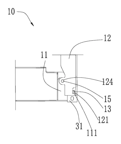
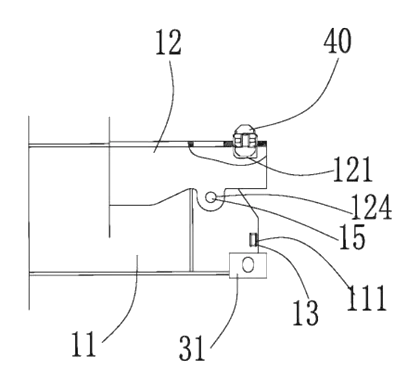
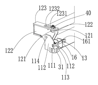
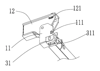
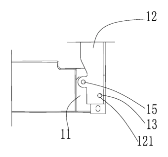
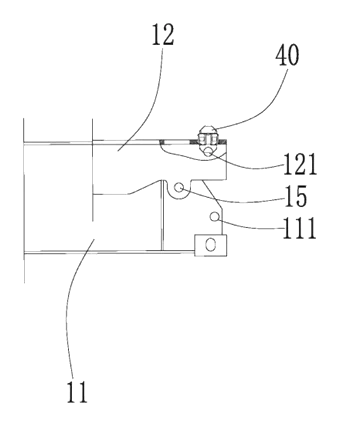
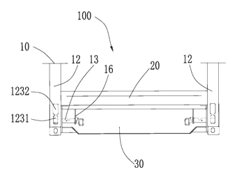
Drawings reproduced from the public patent document for reference.