
Patent CN114098278B
Updated November 7, 2026Folding Table with Safety Lock and Automatic Latch Mechanism
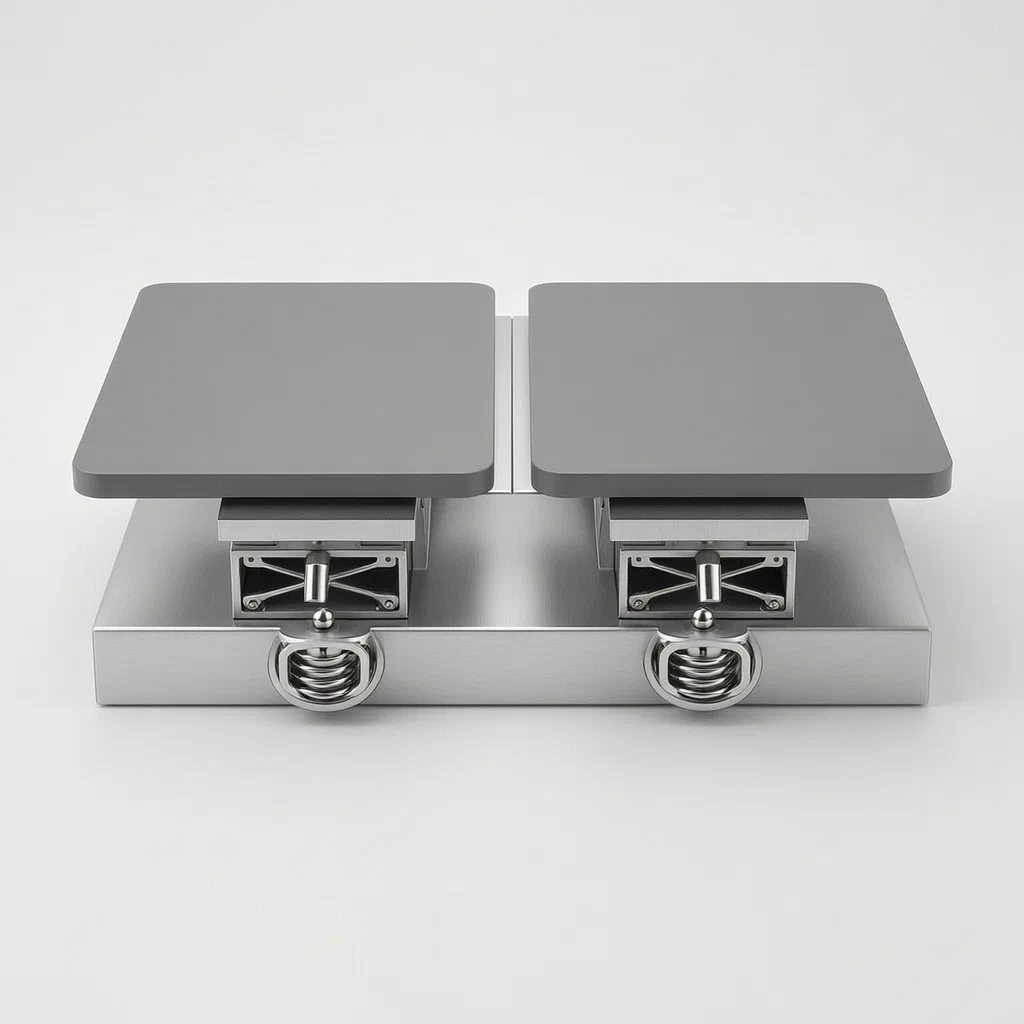
Standard folding tables often rely on simple hinges or manual locks that can loosen over time, leading to wobbling or sudden collapse if the weight shifts. This patent describes a self-locking mechanism where raising the extension plate automatically triggers a sliding bolt into place. The system uses a complex arrangement of springs and rolling elements to ensure the lock engages firmly but releases smoothly when needed, providing stability for dining or work surfaces without requiring user intervention after setup.
- China invention patent - in force
- No filings outside China
- Furniture & Home Office
- Mechanical locking, spring-loaded inserts, sliding grooves
Splat! What let you down?
🔒
Automatic Engagement
The lock activates simply by lifting the extension plate to a horizontal position.
⚙️
Sliding Latch System
A first mechanism in the main plate slides into a second mechanism in the extension plate.
🌀
Elastic Support Assembly
Springs and rolling balls guide the latch movement, reducing friction and wear.
📏
Rigid Surface
Locks the extension plate flush with the main table surface for stable use.
Bring this product to market
- ✓ Patent review Patent family and legal status reviewed in the relevant jurisdictions.
- 2 Product brief · now How it works, uses and options written up
- 3 Prototype First samples for buyers to review
- 4 Pilot run Small first batch for launch customers
- 5 Volume production Repeat orders at scale
Buyer interest
– of 100 buyers needed to start prototyping
One click, no sign-up. Each vote is one real visitor, and products with the most interest go to prototyping first.
Build team: no members yet. Need a partner, co-funding or skills to build this? Join and we introduce the team once it forms.
Patent Rights & Team Participation
Before joining a development team, participants should ensure they have the necessary rights or authorization to participate in the project.
Participation is generally appropriate where:
- You own the relevant patent rights or have obtained permission or a license from the rights holder.
- The relevant patent rights have expired or have been legally invalidated in the jurisdictions where the planned activities will take place.
- The planned development, manufacturing, and commercialization activities have been independently assessed and do not infringe applicable patent rights in the relevant jurisdictions.
Important: Being located outside a country where a patent is protected does not automatically exempt you from patent infringement risks. Patent rights may apply based on where development, manufacturing, use, sale, or import activities take place.
IP2M does not grant any patent license or authorization through team participation. Joining a project does not provide permission to use, manufacture, or commercialize patented technology.
The problem
Traditional folding tables often suffer from instability once deployed. Simple hinge designs allow the extension leaf to wobble under lateral pressure, and manual latch systems require users to remember to secure them. If a latch is forgotten or fails, the table can collapse unexpectedly, especially when weight is placed near the edge. Furthermore, existing locking mechanisms can be difficult to operate, requiring significant force to engage or disengage, which leads to user frustration and potential damage to the furniture joints over time.
The solution
- Structure: A table frame supports a fixed movable plate (1) and a rotatable extension plate (3). The extension plate folds down for storage and lifts up for use.
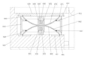
- First Locking Mechanism (4): Located in a groove on the underside of the movable plate. It contains a sliding insert block (410) pushed by an elastic support assembly (6).
- Second Locking Mechanism (5): Located in a groove on the underside of the extension plate. It features a receiving cavity and a trigger piece (540).
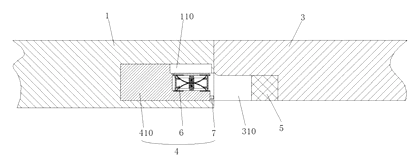
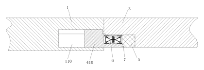
- Engagement: When the extension plate is lifted to be level with the movable plate, the sliding insert block (410) moves laterally. An insertion column (7) attached to the block enters the second locking mechanism (5).
- Locking Action: The insertion column engages with a clamping hook (535) inside the second mechanism. Simultaneously, the elastic assembly ensures the block stays pressed against the top surface of the extension plate’s groove, preventing vertical play.
- Release: To fold the table, the user manipulates the trigger piece (540), which retracts the clamping hook, allowing the sliding insert block to move back out of the locked position.
Who it is for
- Home Furniture Brands: Seeking to offer premium, easy-to-use space-saving tables for apartments and small homes.
- Commercial Cafe Suppliers: Needing durable, quick-setup tables that ensure safety and stability in high-turnover environments.
- Office Equipment Manufacturers: Producing modular meeting tables where seamless surface continuity is critical for presentations and work.
- RV and Marine Interiors: Requiring robust locking mechanisms that withstand vibration and movement while maintaining a flat surface.
How it works
The main parts
| No. | Part | What it does |
|---|---|---|
| 1 | Movable Plate | Main table surface; houses the first locking mechanism. |
| 3 | Extension Plate | Secondary surface; rotates up to join the main plate. |
| 4 | First Locking Mechanism | Sliding assembly with insert block (410) and springs. |
| 5 | Second Locking Mechanism | Receiver in the extension plate with hook (535) and trigger. |
| 6 | Elastic Support Assembly | Springs (620, 640) and rolling balls (661, 671) guide movement. |
| 7 | Insertion Column | Connects the first mechanism to the second; has slots for hooks. |
| 540 | Trigger Piece | User-operated lever to release the lock. |
Operating Steps
- Lift the Extension Plate: Rotate the extension plate (3) upwards until it is flush with the movable plate (1).
- Automatic Slide: As the plates align, the geometry of the grooves causes the sliding insert block (410) to move horizontally toward the extension plate.
- Engage: The insertion column (7) enters the second locking mechanism (5). The clamping hook (535) snaps into the slot on the column, locking the plates together.
- Secure: The elastic support assembly (6) presses the insert block upward, eliminating gaps between the plates.
- Fold Down: Press the trigger piece (540) to retract the hook, then push the extension plate down.
Applications
Dining Rooms
Ideal for expandable dining tables where guests expect a stable, wobble-free surface during meals. The automatic lock ensures no one needs to fiddle with latches before sitting down.
Small Apartments
Perfect for studio living where a desk converts to a dining table. The mechanism allows for rapid deployment and secure locking, maximizing usable space without compromising safety.
Corporate Meeting Spaces
Suitable for conference rooms where tables must present a seamless look. The hidden locking mechanism maintains aesthetic continuity while supporting heavy laptops and documents.
Hospitality Venues
Effective for hotel banquet halls or cafes that need quick setup. Staff can deploy tables efficiently, knowing the safety lock engages automatically upon opening.
Where it is less suitable
- Ultra-lightweight portable tables: The added complexity of the spring-loaded locking mechanism increases weight and cost compared to simple strap-based folding tables.
- Outdoor rugged use: Exposed moving parts like the trigger piece may require additional sealing against dust and moisture for prolonged outdoor exposure.
Patent & Production
At a glance
| Patent number | CN114098278B (application CN202111430073) |
| Type | China invention patent (发明专利) - protects product structure and method |
| Original title | Folding table with safety lock (一种带有安全锁扣的折叠桌) |
| Patent owner | Dongguan Yafulai Furniture Co ltd |
| Inventors | Fang Xiaobin |
| Filing date | 2021-11-29 |
| Grant date | 2022-10-11 |
| Status (China) | In force until at most 2041-11-29 (if annual fees are paid) |
| Patent family | Public record shows Chinese filings only - no US, European, Japanese, PCT or other filings listed |
| Cited by | 0 later documents |
| Source | Google Patents (search for CN114098278B) |
What the claims cover, in plain language
Claim 1 defines a folding table with a movable plate (1) and an extension plate (3). A first locking mechanism (4) slides in a groove on the movable plate, and a second locking mechanism (5) is in the extension plate. When the extension plate is lifted, the mechanisms engage automatically. The first mechanism includes a sliding insert block (410) with an elastic support assembly (6) comprising springs and rolling balls. An insertion column (7) connects the block to the second mechanism.
Claim 2 specifies the table frame structure, including a supporting frame (210) with legs (220) and a sliding rail connection. Claim 3 details the rotation axis (240) between connecting plates (230) for the extension plate. Claim 4 describes the extension plate as consisting of two pivotally connected folding plates. Claim 5 introduces a first sensor on the movable plate side that triggers the locking mechanism protrusion when the extension plate is level. Claim 6 elaborates on the second locking mechanism’s internal structure: a fixing block, installation cavity, and a clamping piece (530) with a hook (535) and trigger piece (540). Claim 7 adds a control portion with pressure sensors to detect articles on the table, preventing unlocking if items are present.
This is a simplified reading for orientation only. The legal scope is defined by the exact claim wording in the official Chinese document.
What this means for US production
This patent was filed in China and is currently in force. Making or selling this specific design in China requires the owner’s permission. The public record shows no US counterpart.
Two points to settle early:
- Other patents may exist. Folding table mechanisms are a competitive field. While this specific combination of spring-loaded rolling balls and dual-groove locking appears unique to this filing, prior art regarding “drop-leaf” tables and “automatic latch” furniture hardware is extensive. A freedom-to-operate (FTO) review is recommended to ensure no other active US patents cover similar locking geometries.
- Sensor implementation. Claims 5 and 7 involve electronic sensors (pressure/position). Manufacturing these adds complexity compared to purely mechanical versions. Decide early if you will implement the electronic control logic or stick to the mechanical base (Claims 1-4).
Customization and manufacturing
What can be customized
| Area | Options |
|---|---|
| Material | MDF, solid wood, or metal composite for plates; steel or aluminum for frame. |
| Size | Standard dining dimensions or custom office/RV sizes. |
| Finish | Powder coating for metal parts; veneer or laminate for wood surfaces. |
| Locking Force | Spring stiffness can be tuned for lighter or heavier plates. |
| Sensors | Option to include or omit the electronic trigger/sensor modules (Claims 5-7). |
| Mounting | Wall-mounted, freestanding, or integrated into larger furniture units. |
Things to plan for (US market)
- ASTM F1938 - Standard practice for evaluating the performance of drop-leaf tables; relevant for safety and durability testing.
- CPSC 16 CFR 1500/1501 - General safety requirements for consumer products; sharp edges or pinch points in the locking mechanism must be evaluated.
- California Prop 65 - If using certain plastics or coatings, chemical disclosure may be required.
- UL/FCC - Only applicable if the electronic sensor version (Claim 7) is produced for sale in the US.
How a project runs
- Inquiry - Define material, size, and whether electronic sensors are included.
- Design - CAD modeling of the locking interface; simulation of spring forces.
- Prototype - CNC machined or 3D printed parts for fit and function testing.
- Pilot Run - Injection molding for plastic lock components; welding/bending for frames.
- Production - Assembly of mechanical parts; wiring/testing if sensors are used.
Quantities & timeline
Tooling for injection-molded lock components takes 8-12 weeks. Frame fabrication tooling depends on material choice. Electronic component sourcing adds lead time. Send us your target dimensions, material preferences, quantity estimates and we will reply with options.
Production notes
Tooling and process
Injection molding is typically used for the complex spring housing and insert block components. Steel tube bending and welding form the supporting frame. Wood or MDF machining creates the table plates. Powder coating applies finish to metal parts. PCB assembly is required only if implementing the sensor claims.
Cost drivers
Tube diameter and wall thickness typically affect frame weight and cost. Connector and bracket count influences assembly time. Packaging volume is significant due to the flat-pack nature. Surface finish quality impacts perceived value. Spring fatigue rates determine replacement part costs.
Prototyping path
We would typically start with a 3D model and load path check. Create a welded or bolted frame sample. Use 3D-printed connectors for initial lock testing. Conduct load tests on the frame. Proceed to tooling and first article inspection.
What we would change before tooling
We would likely simplify the rolling ball guidance if cost is a priority, replacing it with standard bushings. We would verify the spring rate consistency across batches. We would adjust the wall thickness and joint design to prevent stripping screws in particle board substrates.
Common failure points
Loose joints after repeated load are a risk. Insufficient load rating can cause plate sagging. Tipping under uneven load must be tested. Stripped screws in particle board are common in cheap prototypes. Coating chips at edges occur during shipping. Wire routing and strain relief issues arise in sensor-equipped models. Hinge boss and pivot wear limits lifespan.
Patent drawings
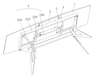
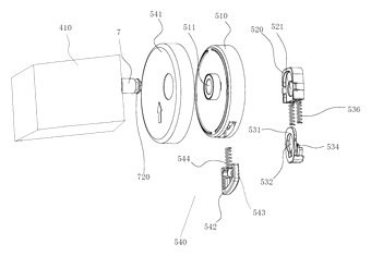
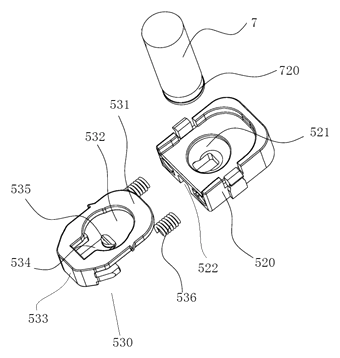
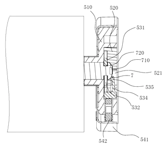
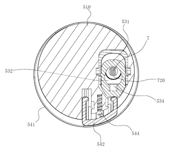
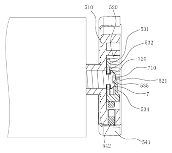
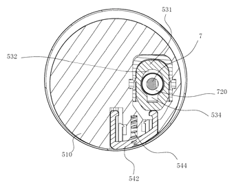
Drawings reproduced from the public patent document for reference.
Frequently asked questions
How does the automatic lock work?
When you lift the extension plate to match the height of the main table, a spring-loaded slider inside the main plate pushes an insertion column into a receiver in the extension plate. A hook snaps into place, locking the two sections together without any manual latching.
Do I have to press a button to unlock it?
To fold the table down, you need to activate the release mechanism. In the basic mechanical version, this involves pushing a trigger piece or tab located on the underside of the extension plate. This retracts the hook, allowing the slider to move back.
Is there an electronic version?
Yes. The patent describes optional sensors (pressure and position) that can prevent the table from unfolding if objects are left on it. However, the core locking function is purely mechanical and does not require electricity.
What materials are used for the lock?
The patent mentions sliding blocks, springs, and rolling balls. These are typically made from engineering plastics (like POM or Nylon) or metals (steel/aluminum) depending on the load requirements and budget.
Can this design be made and sold in the US?
The patent was filed in China and is currently in force there. The public record shows no US counterpart, so this specific patent does not restrict making or selling the design in the US. However, other US patents may cover similar folding table technologies, so a freedom-to-operate check is recommended before mass production.
Are you affiliated with the patent owner?
No. IP2M is an independent design and manufacturing service working from the public patent document.
Request a quote
Click Request a Quote below to see our email address - copy it, or open your email app with a ready-made message. Please mention patent CN114098278B in the subject.
Helpful details to include:
- Your company and channel (home furniture brand, commercial supplier, RV outfitter)
- Target dimensions (length, width, height)
- Materials preference (wood, metal, composite)
- Feature set (mechanical only vs. electronic sensor version)
- Estimated quantity and target price
- Timeline - when you would like samples and the first shipment
You can also reach us at (332) 203-9997.
Page editor: Daniel Chen, Product Research Editor · IP2M
Last updated November 7, 2026. If something on this page looks wrong, email [email protected] and we will check it against the patent.
Interested in building this?
Tell us your target market, quantity and timeline. We reply with options for prototyping, small-batch runs or volume production.
Send your inquiry to
Please put CN114098278B in the subject line and tell us your company, country, estimated quantity and timeline.
Prefer to talk? Call (332) 203-9997.
More product-ready patents
All Furniture, Bedding & Storage patents →
Furniture, Bedding & Storage
Roll-Up Travel Neck Pillow with Buckles
U-shaped travel pillow with a front buckle and a back buckle that holds it rolled up for carrying.
Patent CN206543091U
Furniture, Bedding & Storage
Width-Adjustable Slide Rail for Pull-Out Baskets
Basket slide rail on a slotted, scaled adjusting plate, so one pull-out basket fits several cabinet widths.
Patent CN208909382U
Furniture, Bedding & Storage
Lift-Up Storage Bed with Four-Bar Linkage That Slides the Deck Away from the Headboard
Storage bed deck that rises on four-bar linkages and gas springs, clearing the headboard as it opens.
Patent CN210870645U
Furniture, Bedding & Storage
Self-Leveling, Nesting Table Base with a Torsion-Ring Leg Hub
Four-leg base that self-levels through a torsion-ring hub and nests sideways with flip-top tables.
Patent CN211483640U
Furniture, Bedding & Storage
Rack-and-Pinion Synchronized Drawer Slide with a Folded-In Fixed Rail
Full-extension drawer slide: a pinion between two racks keeps the rails moving in step.
Patent CN206314843U
Furniture & Bedding
Dual-Zone Split-Spring Mattress with Removable Fabric Cover
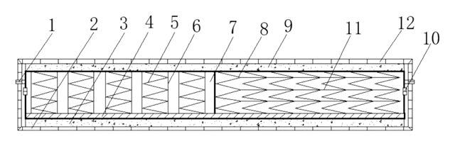
Half-pocket, half-standard spring mattress sharing one base plate, with a removable cover.
Patent CN208355064U
Browse by category
- Apparel & Accessories (48)
- Baby & Kids (29)
- Bags & Luggage (17)
- Bath & Personal Care (32)
- Car Accessories (25)
- Furniture, Bedding & Storage (24)
- Garden & Outdoor (32)
- Health & Wellness (14)
- Home, Kitchen & Cleaning (50)
- Lighting (23)
- Packaging & Containers (12)
- Pet Products (11)
- Phone & Camera Accessories (9)
- Retail Display (25)
- School, Office & Art (36)
- Sports & Recreation (46)
- Tools & Workshop (54)
- Toys & Games (22)
This page is based on the public patent document CN114098278B, assigned to Dongguan Yafulai Furniture Co ltd. IP2M is an independent manufacturing service and is not affiliated with, endorsed by or licensed by the patent owner. Images marked as concept renderings are illustrations, not photos of an existing product. Patent status information is provided for reference only and is not legal advice; confirm freedom to operate for your market before production. Full disclaimer.