
Patent CN114145603B
Updated October 26, 2026Dynamic Display Stand for Indoor Furnishing with Motor-Driven Moving Plates
Static shelves leave products sitting flat, making it hard to catch the eye of shoppers walking past. This dynamic display stand solves that by turning rotation into vertical movement. A driving motor inside the supporting counter spins a bearing column, which drives a hollow central column. Inside that column, connecting rods ride against a guide sliding ring with an irregular undulating profile. As the ring's shape changes, the rods push supporting rods outward through holes in the central column. Those rods carry movable plates fitted with display surfaces, dust covers and label plates. The result is a set of items that rise and fall in sequence while the whole assembly rotates. The unit sits under a bottomless rectangular glass cover fixed to a limiting block, keeping the mechanism enclosed. Two sliding cabinet doors on the supporting counter give staff access to stored supplies without opening the display area.
- China invention patent - in force
- No filings outside China
- Retail & showroom display
- Motor-driven reciprocating motion, glass enclosure, LED lighting
Splat! What let you down?
⚙️
Reciprocating motion
An irregular guide sliding ring turns the motor's rotation into up-and-down movement for each display plate.
🏗️
Enclosed design
A bottomless rectangular glass cover protects the moving parts while keeping the products visible.
💡
Integrated lighting
An LED lamp strip, battery pack and control assembly sit near the top of the central column.
🚪
Built-in storage
Sliding cabinet doors on both sides of the supporting counter hold supplies out of sight.
Bring this product to market
- ✓ Patent vetted China-only family and legal status checked
- 2 Product brief · now How it works, uses and options written up
- 3 Prototype First samples for buyers to review
- 4 Pilot run Small first batch for launch customers
- 5 Volume production Repeat orders at scale
Buyer interest
– of 100 buyers needed to start prototyping
One click, no sign-up. Each vote is one real visitor, and products with the most interest go to prototyping first.
Build team: no members yet. Need a partner, co-funding or skills to build this? Join and we introduce the team once it forms.
The problem
Standard retail shelves and pedestals hold products in a fixed position. Shoppers passing by see the same angle every time, and small items get lost among larger ones on crowded counters. Adding separate motors to each shelf increases wiring complexity and takes up floor space. Staff also need a place to keep price tags, cleaning cloths and spare stock close to the display without cluttering the sales floor.
The solution
This display stand combines rotation and vertical movement in one enclosed unit.
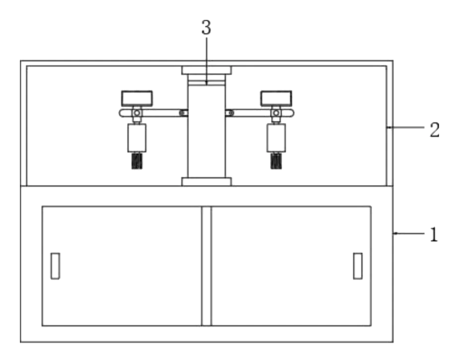
- A driving motor (7) bolted inside the supporting counter (1) spins a cylindrical bearing column (6).
- Arc-shaped connecting blocks (24) at the base of the central column (14) sit in connecting grooves (25) on the bearing column, transferring the rotation.
- Inside the central column, connecting rods (8) pivot on a circular fixing plate (13). Their sliding ball blocks (22) rest in the chute of a guide sliding ring (5).
- The guide sliding ring has an irregular undulating profile. As the column turns, the profile pushes the connecting rods back and forth.
- Movable rods I (21) link the connecting rods to connecting plates II (18), which push the supporting rods (10) through holes in the central column.
- Each supporting rod carries a movable plate (11) inside a movable hole (17). The movable plate holds a display plate (15) on top, a dust cover (9) above that, and a label plate (12) underneath.
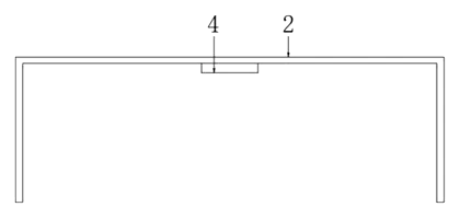
- A limiting block (4) fixed inside the glass cover (2) keeps the central column aligned.
- An LED lamp strip, battery pack and control assembly are mounted near the top of the central column.
Who it is for
- Retail store fixture brands looking to add a motorized pedestal to their catalog for shop owners who want moving displays without building custom mechanisms.
- Jewelry and watch sellers needing a secure, enclosed stand where small items rise and fall to catch light and attention behind glass.
- Trade show booth builders who require compact, self-contained display units with integrated power and lighting that can be set up quickly on convention floors.
- Museum and gallery shops selling reproductions or small artifacts, where controlled motion draws visitors toward the counter without touching the items.
How it works
The main parts
| No. | Part | What it does |
|---|---|---|
| 1 | Supporting counter | Base housing the motor; contains storage behind sliding doors. |
| 2 | Glass cover | Bottomless rectangular enclosure protecting the display device. |
| 4 | Limiting block | Hollow cylinder fixing the central column’s position inside the glass cover. |
| 5 | Guide sliding ring | Irregular undulating profile that converts rotation into reciprocating motion. |
| 6 | Bearing column | Cylindrical shaft driven by the motor, connected to the central column. |
| 7 | Driving motor | Bolted inside the counter, provides rotational power. |
| 8 | Connecting rods | Pivot on the fixing plate; transfer motion from the guide ring to the supporting rods. |
| 10 | Supporting rods | Rectangular bars extending through the central column to carry the movable plates. |
| 11 | Movable plate | Holds the display plate, dust cover and label plate; slides within the movable hole. |
| 13 | Fixing plate | Circular plate inside the central column providing pivot points for the connecting rods. |
| 14 | Central column | Hollow cylinder that rotates and houses the linkage mechanism. |
| 15 | Display plate | Top surface where the product rests. |
Operating steps
- Power on - the control assembly activates the driving motor inside the supporting counter.
- Rotation - the motor turns the bearing column, which spins the central column via the connecting blocks and grooves.
- Vertical movement - the sliding ball blocks follow the irregular profile of the guide sliding ring, pushing the connecting rods inward and outward.
- Display action - the connecting rods push the supporting rods through the central column’s holes, causing the movable plates and display plates to rise and fall in sequence.
- Storage access - staff open the sliding cabinet doors on the counter’s sides to retrieve supplies while the display runs.
Applications
Jewelry counters
Small rings, pendants and watches sit on the display plates. The rising and falling motion catches overhead lighting from different angles, helping passersby notice items that would otherwise blend into a static tray.
Trade show booths
Exhibitors place prototypes or promotional goods on the stand. The glass cover prevents attendees from handling unfinished samples, while the integrated battery pack removes the need to run extension cords across the booth floor.
Museum gift shops
Reproductions of artifacts or small sculptures are displayed dynamically. The enclosed glass cover protects the items from dust and handling, and the label plates underneath allow staff to swap pricing information without stopping the mechanism.
Electronics retail
Wearable devices or small gadgets are presented on the moving plates. The dust cover shields the screens from fingerprints during busy hours, and the LED lamp strip highlights the products against the shop’s background lighting.
Where it is less suitable
- Heavy industrial parts - the supporting rods and movable plates are sized for small indoor furnishings; heavy items require reinforced steel platforms.
- Outdoor environments - the glass cover, motor and battery pack are designed for indoor use and lack weather sealing.
- Large furniture display - this stand is a countertop or pedestal unit, not a platform for full-size chairs or tables.
Frequently asked questions
How do the display plates move up and down?
A driving motor spins a central column. Inside, connecting rods have sliding ball blocks that ride against a guide sliding ring with an irregular wavy profile. As the column turns, the changing shape of the ring pushes the rods in and out, which extends and retracts the supporting rods holding the display plates.
Is the mechanism visible to customers?
No. The moving parts are enclosed inside a bottomless rectangular glass cover that sits on the supporting counter. Customers see the products rising and falling through the glass, but the linkage remains hidden behind the central column and glass walls.
How is the stand powered?
The patent describes a battery pack and control assembly located near the top of the central column. For production, the power system can be configured as a rechargeable battery or adapted to a wired power supply, to be confirmed in design based on the installation site.
Can the vertical stroke be changed?
Yes. The distance the display plates travel depends on the profile of the guide sliding ring. A deeper wave creates a longer stroke. The exact stroke length is set in design and confirmed on prototypes.
What goes on the label plate?
The label plate is mounted on the bottom of the movable plate, beneath the display surface. It is intended for pricing, product names or descriptions, allowing staff to update information without removing the displayed item.
Does the counter offer storage?
The supporting counter has two sliding cabinet doors, one on each side. The internal space holds supplies, extra stock or cables, keeping the sales floor clear while the display operates above.
Can this design be made and sold in the US?
The patent was filed only in China and is currently in force there (until at most 2041-12-20, if annual fees are paid). It has no US counterpart, so it does not restrict making or selling the design in the United States. However, other US patents may cover similar motorized display mechanisms - see Patent & Production - so we recommend a freedom-to-operate check before volume production.
Are you affiliated with the patent owner?
No. IP2M is an independent design and manufacturing service working from the public patent document.
Request a quote
Click Request a Quote below to see our email address - copy it, or open your email app with a ready-made message. Please mention patent CN114145603B in the subject.
Helpful details to include:
- Your company and channel (retail fixture brand, jewelry seller, trade show builder, museum shop)
- Target dimensions for the glass cover and overall height
- Number of display plates needed per unit
- Power preference (battery or wired)
- Materials for the counter and glass type
- Estimated quantity and target price
- Timeline - when you would like samples and the first shipment
You can also reach us at (332) 203-9997.
Explore this product
Interested in building this?
Tell us your target market, quantity and timeline. We reply with options for prototyping, small-batch runs or volume production.
Send your inquiry to
Please put CN114145603B in the subject line and tell us your company, country, estimated quantity and timeline.
Prefer to talk? Call (332) 203-9997.
More product-ready patents
All Retail Display patents →
Retail Display
Motorized Shelf Display That Presents a Product to Shoppers
Shelf unit that lifts a product over the price rail toward shoppers when a sensor detects them.
Patent CN215077184U
Retail Display
Portable Advertising Light Box with Spinning LED Display
Portable ad box whose spinning LED bars draw images and text; content changes by wireless or USB.
Patent CN207425291U
Retail Display
Automated Folding Store Shelf That Pushes Products Up to the Customer
Double-sided shelf for unmanned stores: folding tiers, screw pushers and lift cylinders present stock.
Patent CN109645754B
Retail Display
Motorized Rotating Display Pedestal with Lift Column, Info Screen and Clip-On Display Racks
Mobile pedestal: motorized rotating cube with lit faces and racks, electric lift column and info screen.
Patent CN208875862U
Retail Display
Thin Outdoor LED Video Wall Cabinet with Magnetic Modules and Tool-Free Locks
Thin outdoor LED wall cabinet: magnetic modules and rear body, rotary locks, finned rear cooling.
Patent CN205354557U
Store & Display
Magnetically Repositionable LED Advertising Panel
LED panel whose lamp beads slide to new positions via an external electromagnet.
Patent CN205487209U
Browse by category
- Apparel & Accessories (22)
- Baby & Kids (16)
- Bags & Luggage (9)
- Bath & Personal Care (16)
- Car Accessories (10)
- Furniture, Bedding & Storage (12)
- Garden & Outdoor (18)
- Health & Wellness (8)
- Home, Kitchen & Cleaning (24)
- Lighting (12)
- Packaging & Containers (6)
- Pet Products (6)
- Phone & Camera Accessories (4)
- Retail Display (13)
- School, Office & Art (19)
- Sports & Recreation (25)
- Tools & Workshop (27)
- Toys & Games (12)
This page is based on the public patent document CN114145603B, assigned to Southeast university chengxian college. IP2M is an independent manufacturing service and is not affiliated with, endorsed by or licensed by the patent owner. Images marked as concept renderings are illustrations, not photos of an existing product. Patent status information is provided for reference only and is not legal advice; confirm freedom to operate for your market before production. Full disclaimer.