
Patent CN114190630B
Updated November 6, 2026Powered Fan Filter Assembly for Respiratory Masks
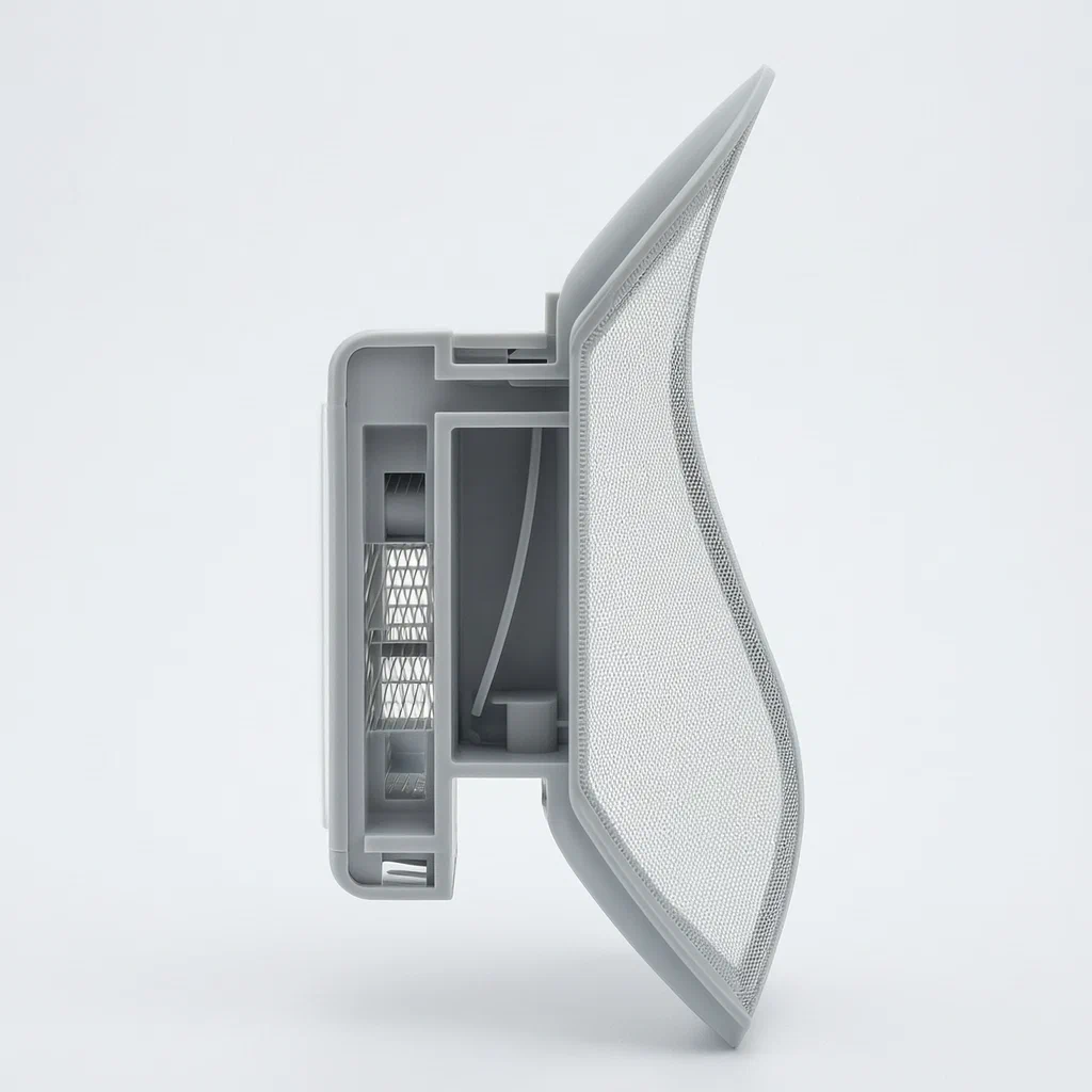
Standard passive masks rely on natural breathing pressure, which can cause heat buildup and fogging in glasses. A powered fan filter unit solves this by mechanically drawing fresh, filtered air into the mask while venting warm, moist exhalation out through a dedicated one-way valve. In this design, the unit splits into an intake section with a fixed column and guide channel, and an exhaust section with a tilted seat for the valve. The two sections snap together around the mask's opening, creating separate vertical paths for incoming and outgoing air. The fan sits behind the filter material in the intake section, pulling ambient air directly into the wearer's breathing space.
- China invention patent - in force
- No filings outside China
- Respiratory protection accessories
- Plastic housing, electric fan, filter media, rigid valve
Splat! What let you down?
🌬️
Active Air Intake
An internal fan draws external air through a filter into the mask, reducing breathing resistance.
🚪
One-Way Exhaust Valve
A rigid valve plate tilts open for exhalation and seals shut to prevent outside air from entering.
🔗
Snap-On Housing
Two detachable shell parts clamp onto the mask’s mounting area, separating intake and exhaust paths.
📏
Vertical Flow Separation
Intake and exhaust channels are arranged vertically relative to a divider line to keep air streams distinct.
Bring this product to market
- ✓ Patent review Patent family and legal status reviewed in the relevant jurisdictions.
- 2 Product brief · now How it works, uses and options written up
- 3 Prototype First samples for buyers to review
- 4 Pilot run Small first batch for launch customers
- 5 Volume production Repeat orders at scale
Buyer interest
– of 100 buyers needed to start prototyping
One click, no sign-up. Each vote is one real visitor, and products with the most interest go to prototyping first.
Build team: no members yet. Need a partner, co-funding or skills to build this? Join and we introduce the team once it forms.
Patent Rights & Team Participation
Before joining a development team, participants should ensure they have the necessary rights or authorization to participate in the project.
Participation is generally appropriate where:
- You own the relevant patent rights or have obtained permission or a license from the rights holder.
- The relevant patent rights have expired or have been legally invalidated in the jurisdictions where the planned activities will take place.
- The planned development, manufacturing, and commercialization activities have been independently assessed and do not infringe applicable patent rights in the relevant jurisdictions.
Important: Being located outside a country where a patent is protected does not automatically exempt you from patent infringement risks. Patent rights may apply based on where development, manufacturing, use, sale, or import activities take place.
IP2M does not grant any patent license or authorization through team participation. Joining a project does not provide permission to use, manufacture, or commercialize patented technology.
The problem
Passive masks often trap heat and moisture because they rely solely on the wearer’s lung pressure to pull air through the fabric. This creates a humid microclimate inside the mask, leading to discomfort, skin irritation, and fogging of eyewear. Additionally, when the mask fits tightly against the face, inhalation becomes difficult due to high resistance across the filter material. Users frequently adjust their masks or take breaks to relieve this pressure, compromising continuous protection. There is a need for a lightweight accessory that reduces inhalation effort and manages exhaust flow without adding significant bulk or weight to the standard mask structure.
The solution
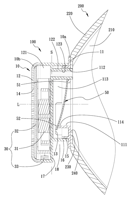
- Housing Structure: The device comprises a first shell (exhaust part) and a second shell (intake part). These two shells combine detachably around the mask’s mounting portion.
- Flow Separation: A separation line divides the intake and exhaust zones. The intake part features a fixed column extending toward the mask, passing through a guide channel to deliver filtered air into the wearing space.
- Exhaust Mechanism: The exhaust part contains an exhaust channel aligned vertically with the intake path. It connects to an exhaust hole via a group connection hole.
- One-Way Valve: A rigid exhaust check valve body is mounted on an inclined seat within the exhaust part. It swings open away from the axis when the user exhales, allowing air to exit, and closes to block backflow.
- Fan Assembly: Inside the intake part, a fan filter assembly includes a suction piece (fan), a power supply, and filter material. The fan pulls external air through the filter and directs it into the mask.
Who it is for
- Outdoor Workwear Brands adding ventilation accessories to dust-proof or cold-weather masks for construction or agriculture workers.
- Medical Supply Distributors seeking enhanced comfort options for surgical-style masks used in long shifts.
- Industrial Safety Suppliers providing respiratory aids for environments where heavy exertion makes passive masks uncomfortable.
- Consumer Electronics Makers integrating small fans into wearable health or lifestyle products like smart masks.
How it works
The main parts
| No. | Part | What it does |
|---|---|---|
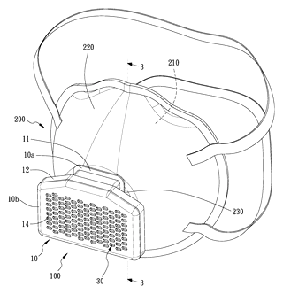
| 10a | First Shell | Houses the exhaust part and valve mechanism. |
| 10b | Second Shell | Houses the intake part, fan, and filter. |
| 11 | Exhaust Part | Channel for outgoing breath; includes tilted seat. |
| 12 | Intake Part | Channel for incoming air; includes fixed column. |
| 30 | Fan Assembly | Motor/fan unit that draws air through the filter. |
| 32 | Filter Material | Placed before the fan to clean incoming air. |
| 50 | Check Valve Body | Rigid plate that opens for exhalation and seals for inhalation. |
| 200 | Mask | The base mask unit with a cut-out mounting area. |
Operating Steps
- Assembly: The first and second shells snap together around the mask’s flat mounting portion, clamping the edges securely.
- Inhalation: When the user inhales, the negative pressure draws external air through the intake hole (14). The air passes through the filter material (32) and is pulled by the fan (31) into the guide channel (123).
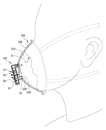
- Air Delivery: Filtered air enters the wearing space (210) inside the mask, providing a steady stream of fresh oxygen.
- Exhalation: When the user exhales, positive pressure pushes the rigid check valve (50) open along its inclined seat (114). Warm, moist air exits through the exhaust hole (13).
- Sealing: During inhalation or when idle, the valve spring action or gravity keeps the check valve closed against the seat, preventing unfiltered outside air from leaking in through the exhaust port.
Applications
Construction and Mining Sites
Workers in dusty environments benefit from the active intake, which ensures consistent filtered air supply even during heavy physical labor, reducing fatigue compared to passive N95-style masks.
Healthcare Settings
Medical staff wearing masks for extended periods experience less heat stress and facial sweating. The separated exhaust path helps reduce fogging on protective eyewear, improving visibility during procedures.
Outdoor Sports and Cycling
Cyclists and runners in cold weather need breathable protection. The fan maintains airflow without requiring the user to loosen the mask, balancing warmth and oxygen intake during high-exertion activities.
Industrial Manufacturing
Factories with volatile organic compounds or particulates require reliable filtration. This unit provides a mechanical assist to overcome filter resistance, ensuring adequate ventilation rates for safety compliance.
Where it is less suitable
- Sterile Surgical Environments - The plastic housings and electronic components may not meet strict sterilization protocols required for direct patient contact in operating rooms.
- Extreme Heat or Fire Zones - The battery and motor components have temperature limits and may fail in very hot industrial settings like smelting.
- Low-Budget Disposable Use - Unlike simple paper masks, this requires reusable electronics and filters, making it unsuitable for single-use low-cost scenarios.
Patent & Production
At a glance
| Patent number | CN114190630B (application CN202010977091) |
| Type | China invention patent (发明专利) - protects product structure and method |
| Original title | Fan filter device for masks (口罩用风扇过滤装置) |
| Patent owner | Jekoro Co ltd |
| Inventors | Wu Jinshu |
| Filing date | 2020-09-17 |
| Grant date | 2024-08-02 |
| Status (China) | In force - valid until at most 2040-09-17, provided annual fees are paid |
| Patent family | Public record shows Chinese filings only - no US, European, Japanese, PCT or other filings listed |
| Cited by | 0 later documents |
| Source | Google Patents (search for CN114190630B) |
What the claims cover, in plain language
Claim 1 - A fan filter for a mask disposed on the outer side, corresponding to the user’s mouth/nose. The device has a shell combined with the mask, split into a first shell (exhaust part) and second shell (intake part). A separation line divides them. The first shell has an air outlet and exhaust hole; the second has an air inlet and inlet hole. Both connect to the mask’s wearing space. The intake part has a fixed column with a guide channel. The exhaust part has a group connection hole. A fan filter assembly (suction piece, power supply, filter material) is in the intake part. An exhaust one-way valve body is in the exhaust part, arranged obliquely. When exhaling, air pushes the valve open to exit; when inhaling, it seals.
Claim 2 - The exhaust part includes an inclined seat. The valve is a rigid plate with a fixed part on the upper edge and a movable part abutting the lower edge.
Claim 3 - The first shell has a positioning portion surrounding the exhaust passage. The second shell has a fastening portion surrounding the fixed column. They fasten together.
Claim 4 - The air inlet is on the side of the second shell along the axis. The air outlet is perpendicular to the axis.
Claim 5 - The second shell has a stopping portion extending outward, forming an exhaust area between it and the fastening portion.
Claim 6 - The mask has a filter wearing part (hemispherical) and a mounting part (flat cut). The shells attach to this flat part. Openings allow flow between channels and the wearing space.
This is a simplified reading for orientation only. The legal scope is defined by the exact claim wording in the official Chinese document.
What this means for US production
This patent was filed in China and is currently in force there. The public record shows no US or other foreign counterpart. Therefore, making or selling this specific design in China requires the owner’s permission. However, since there is no US patent, the design itself does not restrict manufacturing or sales in the United States based on this document alone.
Two points to settle early:
- Other patents may exist. Powered respirators and mask accessories are a crowded field. Major brands hold patents on similar fan-assisted structures, valve mechanisms, and battery integration. A freedom-to-operate (FTO) review is essential to ensure your specific implementation does not infringe on existing US IP.
- Component sourcing. The fan, battery, and filter materials must be sourced separately. Their individual certifications (e.g., UL for batteries, FDA/NIOSH for filters if claiming medical/respiratory performance) are critical and independent of this structural patent.
Customization and manufacturing
What can be customized
| Area | Options |
|---|---|
| Shell Material | ABS, PC, or TPU for flexibility and durability. |
| Fan Type | Brushless DC motors for longevity; variable speed controls. |
| Filter Media | HEPA-grade, activated carbon, or electrostatic meltblown layers. |
| Valve Design | Silicone flaps vs. rigid plates; magnetic return springs. |
| Battery Capacity | 500mAh to 2000mAh depending on runtime needs. |
| Mounting Interface | Clip-on adapters for different mask shapes (N95, cloth, surgical). |
Things to plan for (US market)
- FDA Regulations - If marketed as a medical device (surgical mask), it falls under Class I or II regulations. General wellness claims may avoid strict medical device pathways but still require accurate labeling.
- NIOSH Approval - If used for occupational respiratory protection (dust, chemicals), the filter component must meet NIOSH standards. The structural attachment must not compromise seal integrity.
- UN 38.3 / DOT - Lithium-ion batteries require transport testing and labeling.
- FCC Part 15 - Electronic fans and wireless controllers (if any) must comply with electromagnetic interference rules.
- CPSC - General consumer product safety requirements apply to electrical components and child-accessible parts.
How a project runs
- Inquiry - Define target mask compatibility, battery life, and filtration level.
- Design - CAD modeling of housing, airflow simulation, and component selection.
- Prototype - 3D-printed housings, off-the-shelf fan/battery integration, functional testing.
- Pilot Run - Mold tooling for shells, assembly line setup, quality control checks.
- Production - Injection molding, sub-assembly, final packaging.
Quantities & timeline
Injection molds for the two-part shell are the primary upfront cost. Battery and motor lead times vary globally. Certification testing (electrical safety, biocompatibility if applicable) adds 4-8 weeks. Send us your target mask model, battery specs, and volume estimates and we will reply with options.
Production notes
Tooling and process
The housing typically requires injection molding tools for the first and second shells. The intake and exhaust channels are complex geometries, so multi-cavity molds are likely needed for efficiency. Assembly usually involves heat pressing or screw-fastening of the halves, followed by inserting the fan module.
Cost drivers
Mold costs typically dominate initial investment, especially for tight-tolerance air-seal surfaces. High-grade filter media and brushless motors drive per-unit BOM costs. Packaging must protect fragile electronic components, adding material expenses.
Prototyping path
We would start with 3D-printed resin prototypes to verify fitment on target masks. Test airflow using a mannequin head and pressure sensors. Iterate on valve stiffness and seal gaps before committing to steel molds.
What we would change before tooling
We would simplify the separation line geometry if it causes mold undercut issues. We might integrate the fixed column and guide channel into a single molded feature to reduce part count. Ensuring the valve seat angle matches the rigid plate thickness is critical to prevent leakage.
Common failure points
Air leaks around the mounting interface are common if the mask material compresses unevenly. Valve sticking can occur if humidity condenses on the rigid plate. Electrical failures often stem from vibration loosening solder joints on the fan PCB.
Patent drawings
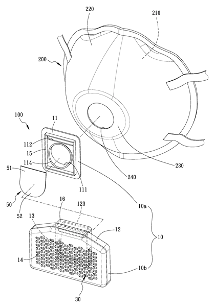
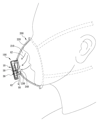
Drawings reproduced from the public patent document for reference.
Frequently asked questions
Does it fit all masks?
The patent describes a mounting part that is flat-cut on the mask. It works best with structured masks like N95s or bowl-shaped masks that have a solid surface area for the clip-on housing. Soft cloth masks may require a different adapter.
How long does the battery last?
The patent mentions a power supply but does not specify capacity. Runtime depends on fan speed and battery size chosen during design. Typical small fans run for several hours on compact lithium cells, but exact numbers are confirmed on prototypes.
Can I wash the device?
The housing is detachable. The electronic fan and battery modules should not be submerged. The filter material is replaceable. Cleaning instructions depend on the final material choice (e.g., wipe-down for plastic shells).
Does it help with glasses fogging?
By directing exhaled air through a separate exhaust valve rather than letting it escape upward around the cheeks, the design aims to reduce airflow toward the eyes. Effectiveness varies by mask fit and valve seal quality.
Is the noise level high?
The patent does not specify decibel levels. Noise depends on the fan RPM and housing insulation. Low-speed brushless motors are typically quieter, but sound tests are done during prototyping.
Can this design be made and sold in the US?
The patent is in force in China, but the public record shows no US counterpart. This means you are not restricted by this specific patent when manufacturing or selling in the US. However, other US patents may cover similar technology, so a freedom-to-operate check is recommended.
Are you affiliated with the patent owner?
No. IP2M is an independent design and manufacturing service working from the public patent document.
Request a quote
Click Request a Quote below to see our email address - copy it, or open your email app with a ready-made message. Please mention patent CN114190630B in the subject.
Helpful details to include:
- Your company and channel (medical distributor, outdoor gear brand, industrial supplier)
- Target mask models and sizes
- Desired battery life and fan speed
- Filter type (HEPA, carbon, etc.)
- Estimated quantity and target price
- Timeline - when you would like samples and the first shipment
You can also reach us at (332) 203-9997.
Page editor: Emily Zhang, Product Editor · IP2M
Last updated November 6, 2026. If something on this page looks wrong, email [email protected] and we will check it against the patent.
Interested in building this?
Tell us your target market, quantity and timeline. We reply with options for prototyping, small-batch runs or volume production.
Send your inquiry to
Please put CN114190630B in the subject line and tell us your company, country, estimated quantity and timeline.
Prefer to talk? Call (332) 203-9997.
More product-ready patents
All Apparel & Accessories patents →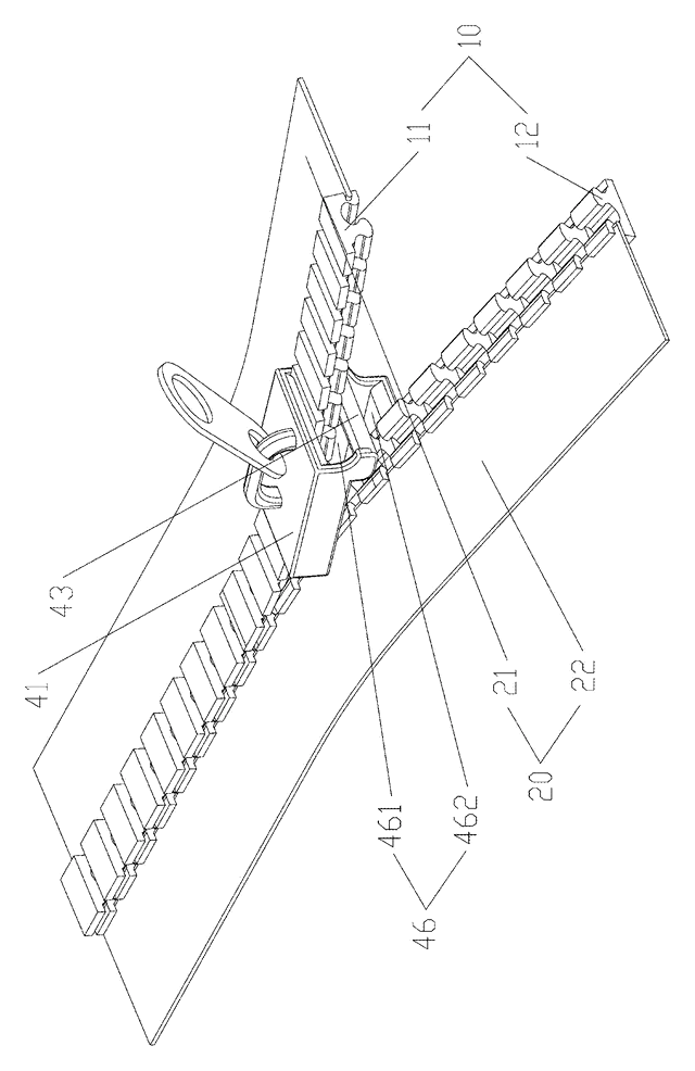
Apparel & Accessories
Stacked Zipper with Teeth That Mesh Top-to-Bottom
Zipper whose two identical tooth rows mesh on top of each other, closed by a simplified slider.
Patent CN205795062U
Apparel & Accessories
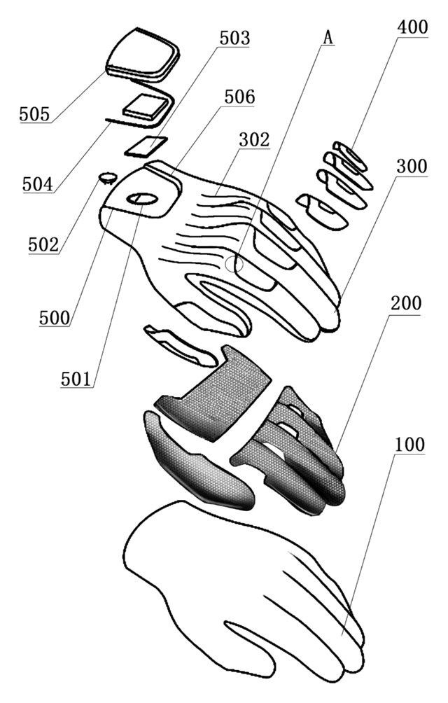
Impact-Resistant Glove with a 3D-Printed Lattice Layer
Work glove with a 3D-printed lattice impact layer, TPU knuckle guards and a light mounting area.
Patent CN213785583U
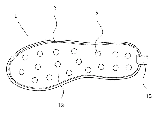
Apparel & Accessories
Massage Insole with Spring-Back Silicone Nubs and a Removable Top Layer
Layered insole: silicone nubs rise through a removable perforated top sheet and sink under each step.
Patent CN208286505U
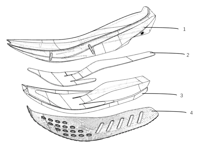
Apparel & Accessories
Heel-Less Carbon Plate Running Shoe Sole for Forefoot Strikers
Running sole for forefoot strikers: no ground-touching heel, winged carbon plate between two midsoles.
Patent CN216723354U
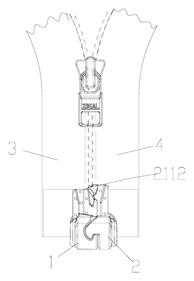
Apparel & Accessories
Waterproof Magnetic Zipper Stop That Snaps the Two Halves Together
Separating-zipper stop with sealed magnets: pin and box snap together one-handed, safe in rain and wash.
Patent CN215075936U
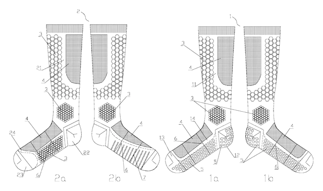
Apparel & Accessories
Left-Right Specific Soccer Socks: Grip for the Plant Foot, Touch Pads for the Kicking Foot
Soccer socks knitted as a left-right pair: grip zones for the plant foot, pads for the kicking foot.
Patent CN212728807U
Browse by category
- Apparel & Accessories (43)
- Baby & Kids (28)
- Bags & Luggage (16)
- Bath & Personal Care (29)
- Car Accessories (23)
- Furniture, Bedding & Storage (22)
- Garden & Outdoor (29)
- Health & Wellness (13)
- Home, Kitchen & Cleaning (46)
- Lighting (22)
- Packaging & Containers (11)
- Pet Products (10)
- Phone & Camera Accessories (9)
- Retail Display (23)
- School, Office & Art (33)
- Sports & Recreation (41)
- Tools & Workshop (50)
- Toys & Games (21)
This page is based on the public patent document CN114190630B, assigned to Jekoro Co ltd. IP2M is an independent manufacturing service and is not affiliated with, endorsed by or licensed by the patent owner. Images marked as concept renderings are illustrations, not photos of an existing product. Patent status information is provided for reference only and is not legal advice; confirm freedom to operate for your market before production. Full disclaimer.