
Patent CN114210074B
Updated November 7, 2026Motorized Ball Track Toy with Rotating Lifting Plates and See-Saw Lift
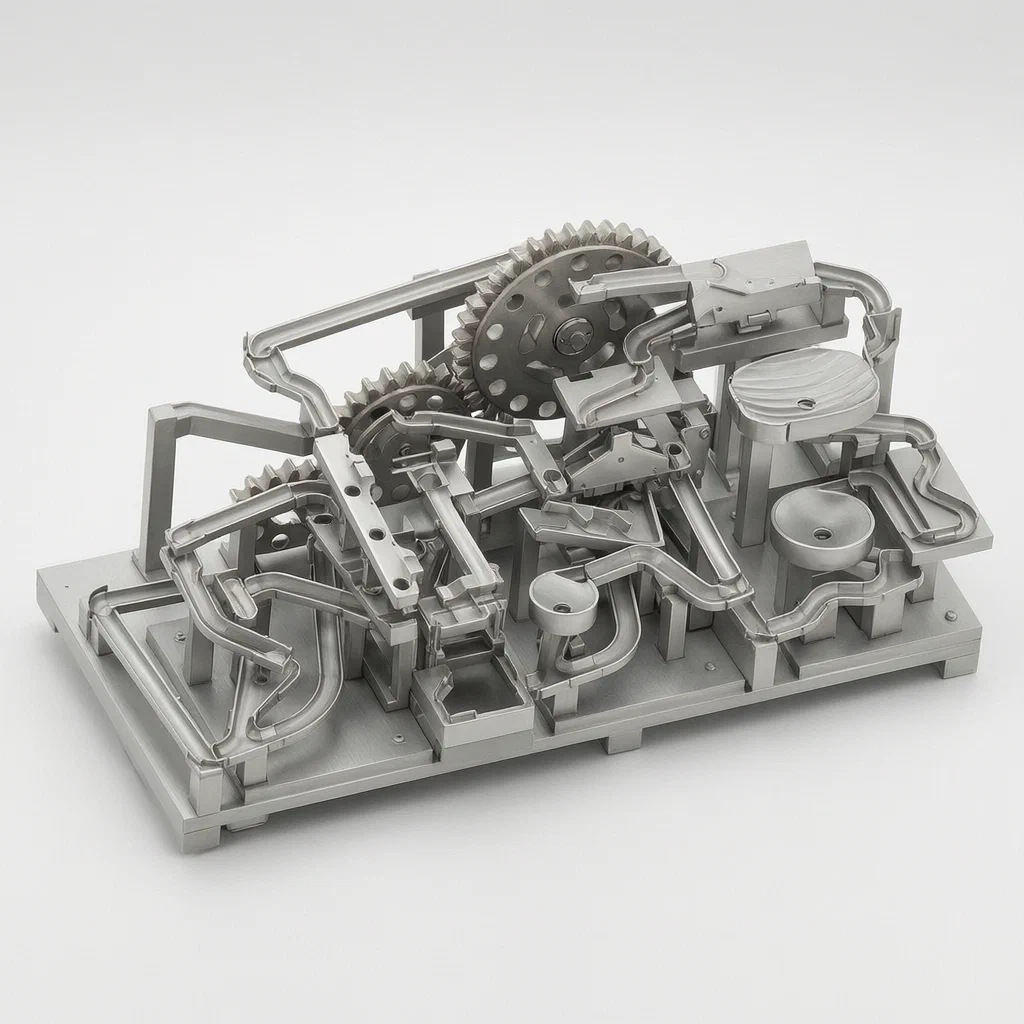
Traditional gravity-fed ball runs often lack dynamic movement or require excessive manual intervention to reset. This design integrates a motorized lifting system where rotating plates with inclined holes lift balls to different heights. It also features a clever see-saw mechanism that uses the rotational energy of one plate to drive a vertical lift for another section, creating continuous, automated circulation loops across three independent tracks.
- China invention patent - in force
- No filings outside China
- Motorized toys & games
- Rotating plates, see-saw lift, gear drive
Splat! What let you down?
🔄
Rotating Lifting Plates
Three ball plates rotate at different heights, using inclined holes to lift balls mechanically.
⚖️
See-Saw Lift Mechanism
A hinged rod driven by plate rotation lifts balls vertically without extra motors.
🛣️
Independent Channels
Three separate track structures create distinct circulation loops on one base.
🔌
Motor-Driven Gears
A single motor drives multiple gears to synchronize the rotation of the lifting plates.
Bring this product to market
- ✓ Patent review Patent family and legal status reviewed in the relevant jurisdictions.
- 2 Product brief · now How it works, uses and options written up
- 3 Prototype First samples for buyers to review
- 4 Pilot run Small first batch for launch customers
- 5 Volume production Repeat orders at scale
Buyer interest
– of 100 buyers needed to start prototyping
One click, no sign-up. Each vote is one real visitor, and products with the most interest go to prototyping first.
Build team: no members yet. Need a partner, co-funding or skills to build this? Join and we introduce the team once it forms.
Patent Rights & Team Participation
Before joining a development team, participants should ensure they have the necessary rights or authorization to participate in the project.
Participation is generally appropriate where:
- You own the relevant patent rights or have obtained permission or a license from the rights holder.
- The relevant patent rights have expired or have been legally invalidated in the jurisdictions where the planned activities will take place.
- The planned development, manufacturing, and commercialization activities have been independently assessed and do not infringe applicable patent rights in the relevant jurisdictions.
Important: Being located outside a country where a patent is protected does not automatically exempt you from patent infringement risks. Patent rights may apply based on where development, manufacturing, use, sale, or import activities take place.
IP2M does not grant any patent license or authorization through team participation. Joining a project does not provide permission to use, manufacture, or commercialize patented technology.
The problem
Standard ball track toys rely heavily on gravity. Once a ball reaches the bottom, it must be manually lifted back to the top to restart the run, which interrupts play and limits engagement. Some motorized versions use elevators or conveyor belts, but these can be noisy, prone to jamming, and difficult to integrate into compact, multi-level designs. Furthermore, maintaining synchronized flow across multiple independent tracks requires complex wiring or separate power sources, increasing cost and failure points.
The solution
The patent introduces a lifting structure integrated directly into the base. Instead of vertical elevators, it uses rotating ball plates (first, second, and third) positioned at sequential height differences. These plates have annularly distributed ball holes with inclined axes. As the plates rotate, the holes scoop up balls from the lower level and deposit them onto the next higher track via transition assemblies.
To handle the heaviest lifting task efficiently, the design incorporates a see-saw assembly. This mechanism connects to the second ball plate. As the plate rotates, a driving rod engages a hinged seesaw rod, causing a lifting table to move up and down. This mechanically transfers balls from a receiving platform to a return groove, effectively acting as a pump powered by the existing rotation system.
Who it is for
- Toy Design Brands: Companies looking to differentiate their marble run products with automated recycling mechanisms that reduce manual user effort.
- STEM Educational Kit Makers: Manufacturers who want to demonstrate simple machines (gears, levers, see-saws) in a functional, engaging product rather than static diagrams.
- Amazon Sellers: Retailers seeking a high-engagement toy with visible moving parts that stand out in video ads compared to passive gravity-only tracks.
- Wholesalers of Interactive Toys: Distributors needing durable, motorized toys that offer continuous play cycles without frequent resetting.
How it works
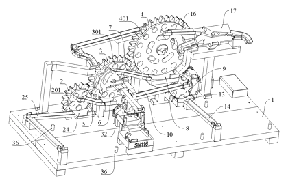
The main parts
| No. | Part | What it does |
|---|---|---|
| 1 | Main Base | Supports all structures and houses the mounting posts. |
| 0 | Lifting Structure | Comprises the rotating plates and transition components. |
| 2, 3, 4 | Ball Plates | First, second, and third plates; rotate to lift balls via inclined holes. |
| 5, 6 | Transition Assemblies | Connect plates; include ball grooves and discs to transfer balls between levels. |
| 7 | Lifting Disc | Top component with bead inlet and blocking blocks to control entry. |
| 8 | Guide Bridge | Directs balls from the lifting disc to the first ball disc. |
| 9 | Diversion Assembly | Splits flow using first and second diversion grooves based on hole orientation. |
| 10 | See-Saw Assembly | Hinged rod and lifting table driven by the second plate’s rotation. |
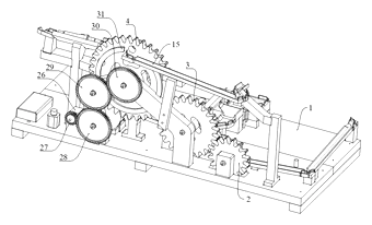
| 11 | Drive Assembly | Motor and gear set connecting to the plates for synchronized rotation. |
| 12 | Track Structures | First, second, and third supports with inlet/outlet grooves and diverters. |
Operating steps
- Ball Entry: Balls are placed in the bead inlet of the lifting disc. The blocking block prevents overflow.
- Transfer to First Level: The guide bridge moves balls to the first ball disc.
- Rotation and Lift: The motor drives the gears, rotating the first, second, and third ball plates. The inclined holes in the plates catch balls and lift them to the next transition assembly.
- Flow Diversion: At the third plate, through-holes and half-through-holes direct balls into either the first or second diversion groove, splitting the stream.
- See-Saw Action: As the second plate rotates, its driving rod pushes the seesaw rod. The lifting table rises, transferring balls from the receiving platform to the third ball return groove.
- Circulation: Balls travel through the respective track structures (first, second, third), navigate curves and diverters, and eventually return to the lifting structure to repeat the cycle.
Applications
Home Entertainment Centers
Children can engage in long-duration play sessions because the balls recycle automatically. Parents do not need to constantly intervene to reset the game, allowing for independent play and reducing frustration when balls reach the end of a gravity-only run.
STEM Education Classrooms
Teachers can use this toy to illustrate mechanical principles such as gear ratios, lever mechanics (the see-saw), and potential vs. kinetic energy. The transparent or open structure allows students to observe how rotational motion converts into vertical displacement.
Retail Display Models
Electronics stores or toy shops can use this as a live display model. The continuous motion attracts attention more effectively than static displays, drawing customers to the booth while demonstrating the product’s durability and smooth operation.
Gift Market for Ages 6+
Packaged as a premium gift item, this toy appeals to parents looking for alternatives to screen-based entertainment. The complexity of the three-channel system offers a longer shelf-life for interest compared to simpler single-track marbles.
Where it is less suitable
- Toddlers (Under 3): The small balls and moving mechanical parts pose choking hazards and pinch risks unsuitable for very young children without strict supervision.
- Outdoor Use: The electronic motor components and precision plastic joints are likely susceptible to damage from dust, moisture, or uneven surfaces.
- Silent Play Environments: Although quieter than some elevator systems, the continuous rotation and clicking of balls in holes may generate noise unsuitable for libraries or quiet offices.
Patent & Production
At a glance
| Patent number | CN114210074B (application CN202111635411) |
| Type | China invention patent - protects method and structure |
| Original title | A Ball Track Toy (一种滚珠轨道玩具) |
| Patent owner | Individual |
| Inventors | Mai Penghua |
| Filing date | 2021-12-29 |
| Grant date | 2023-05-09 |
| Status (China) | In force - valid until at most 2041-12-29 (if annual fees are paid) |
| Patent family | Public record shows Chinese filings only - no US, European, Japanese, PCT or other filings listed |
| Cited by | 0 later documents |
| Source | Google Patents (search for CN114210074B) |
What the claims cover, in plain language
Claim 1 defines the core structure: a main base with a lifting structure and three track structures forming independent channels. The lifting structure uses three rotatable ball plates (first, second, third) with height differences, connected by transition assemblies (ball grooves and discs). The plates have annularly distributed ball holes with inclined axes to lift balls. It includes a lifting disc with a bead inlet, a guide bridge, and a diversion assembly that splits flow using through-holes and half-through-holes. A see-saw assembly is described as part of the mechanism to assist lifting.
Claim 2 specifies that the track structures are detachably mounted on the base using positioning inserting posts and holes. Claim 3 details the first track structure, including supports, inlet/outlet grooves, and ejector rods under specific ball positions. Claim 4 describes the second track structure with a bearing plate, shunt, and rotary disc. Claim 5 outlines the third track structure with a support, inlet/outlet grooves, and flow plates. Claim 6 adds a drive assembly consisting of a motor and meshed gears that connect to the ball plates and lifting disc. Claim 7 elaborates on the see-saw assembly, detailing the support upright, hinged rod, lifting table, hanging ring, and guide rod mechanism. Claim 8 adds a receiving platform engaged with the lifting platform and the third ball return slot.
This is a simplified reading for orientation only. The legal scope is defined by the exact claim wording in the official Chinese document.
What this means for US production
This patent was filed in China and is currently in force there. The public record shows no US or other foreign counterpart. Making or selling this specific design in China would require the owner’s permission. However, since there is no US patent, the design itself is not restricted by this specific patent in the United States.
Two points to settle early:
- Other patents may exist. The toy industry is heavily patented, particularly regarding marble runs, elevators, and gear-driven mechanisms. While this specific combination appears unique in the public record, similar functional elements might be covered by earlier US patents. A freedom-to-operate (FTO) review is recommended before mass production.
- Safety Standards. US regulations for toys are strict. The design involves small balls and moving parts. Compliance with ASTM F963 and CPSIA is mandatory, influencing material choices and structural tolerances more than the patent itself.
Customization and manufacturing
What can be customized
| Area | Options |
|---|---|
| Materials | ABS, PP, or POM for plates and tracks; metal gears for durability. |
| Colors | Pad printing for decorative patterns on plates; clear vs. opaque track sections. |
| Motor Type | DC geared motors with varying RPM to adjust ball speed. |
| Power Source | Battery compartment (AA/AAA) or USB-C rechargeable module. |
| Track Layout | Modular adjustments to the length of diversion grooves or bridge angles. |
| Assembly | Snap-fit joints for ease of assembly vs. screw-fastened for durability. |
Things to plan for (US market)
- ASTM F963: Standard Consumer Safety Specification for Toy Safety. Critical for small parts, sharp edges, and mechanical hazards.
- CPSIA: Consumer Product Safety Improvement Act. Requires testing for lead, phthalates, and tracking labels.
- UL / FCC: If using rechargeable batteries or wireless components, battery safety (UN 38.3) and electromagnetic compatibility tests apply.
- California Prop 65: Warning requirements if certain chemicals are present in plastics or paints.
How a project runs
- Inquiry - Define target age group, price point, and desired feature set (e.g., sound effects, light-up tracks).
- Design - CAD modeling of the gear train, see-saw linkage, and injection mold flows.
- Prototype - 3D-printed samples to test mechanical synchronization and ball flow rates.
- Pilot Run - Tooling validation, drop tests, and small-parts hazard assessment.
- Production - Injection molding of plastic parts, motor assembly, pad printing, and final packaging.
Quantities & timeline
The complexity lies in the interlocking gear system and the precise alignment of the see-saw mechanism. Mold costs will be significant due to the number of unique plastic parts (plates, grooves, supports). Send us your target retail price, estimated volume, and desired materials and we will reply with options.
Production notes
Tooling and process
Injection molding is the primary process for the base, plates, and track segments. The number of molds depends on whether the tracks are modular or fixed. Pad printing applies decorative graphics to the rotating plates. Simple electronics involve assembling the motor and battery housing, potentially using ultrasonic welding for sealed compartments.
Cost drivers
The high number of unique injection molds is typically the largest cost driver. Electronic parts (motor, switch, battery contacts) add unit cost. Packaging must be robust enough to protect the delicate see-saw linkage during transit. Print colors add setup time and piece cost.
Prototyping path
We would typically start with a 3D-printed sample to verify the gear ratios and see-saw geometry. Off-the-shelf electronics should be used initially to test motor torque requirements. A functional sample with snap-fit joints helps identify alignment issues before committing to steel tooling.
What we would change before tooling
We would likely simplify the hinge bosses on the see-saw assembly to prevent cracking after drops. Wall thickness uniformity in the ball plates needs review to avoid sink marks. We would also test magnet strength if magnetic connectors are used for modularity, ensuring they meet safety standards.
Common failure points
Shaft and bearing alignment is critical; misalignment causes grinding or stalling. The see-saw pivot wear is a long-term risk. Small parts like the driving rod on the second plate can break if the motor stalls. Paint wear on high-friction areas may occur over time.
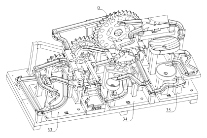
Patent drawings
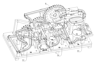
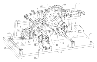
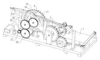
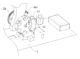
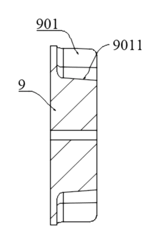
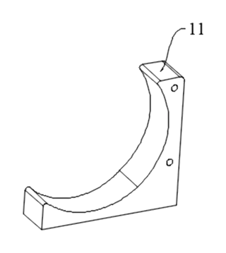
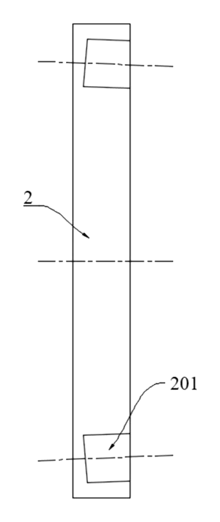
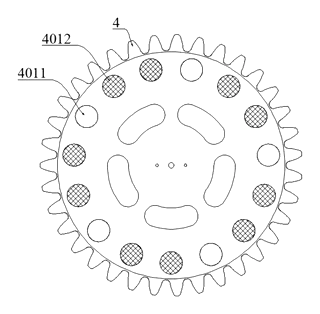
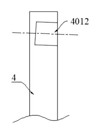
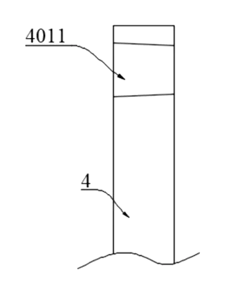
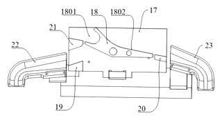
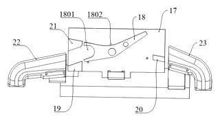
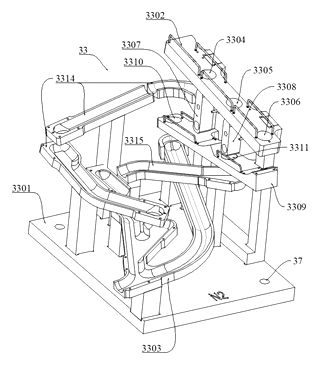
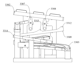
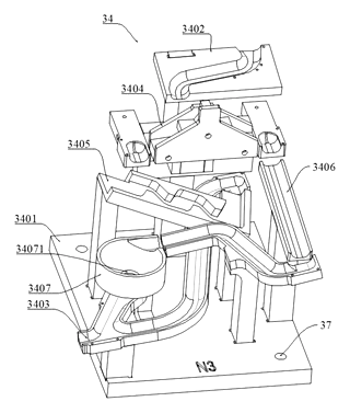
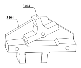
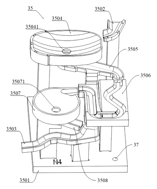
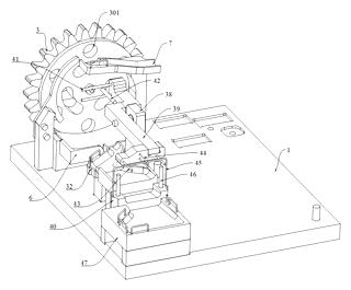
Drawings reproduced from the public patent document for reference.
Frequently asked questions
How does the ball get back to the top?
Instead of a vertical elevator, the toy uses rotating plates with inclined holes. As the motor turns the plates, the holes scoop up balls from the lower track and deposit them onto the next higher level. A see-saw mechanism further assists in lifting balls from the collection area back into the flow.
Is it safe for young children?
It is designed for ages 6 and up. The small balls and moving mechanical parts pose choking and pinch hazards for toddlers. Adult supervision is recommended. The product must pass ASTM F963 small parts testing before sale.
Does it require many batteries?
Typically, one or two AA/AAA batteries power the motor. Alternatively, a USB-C rechargeable module can be used. Battery life depends on the motor efficiency and usage duration, usually lasting several hours of continuous play.
Can I customize the colors and design?
Yes. The plastic parts can be molded in various colors, and pad printing allows for custom graphics on the plates and base. You can also choose different track layouts by modifying the diversion grooves.
How loud is the motor?
The motor is selected for low-noise operation, typically under 50 decibels. The clicking sound of balls moving through the holes is inherent to the design but can be dampened with softer plastic materials or lubricants.
Are the tracks interchangeable?
The patent describes detachable mounting using positioning posts and holes. This allows for modular assembly, meaning you could potentially swap track sections or repair damaged parts without replacing the entire unit.
Can this design be made and sold in the US?
The patent was filed in China and is in force there, but the public record shows no US counterpart. Therefore, this specific patent does not restrict making or selling the design in the US. However, other patents may exist in the field, so a freedom-to-operate check is advised.
Are you affiliated with the patent owner?
No. IP2M is an independent design and manufacturing service working from the public patent document.
Request a quote
Click Request a Quote below to see our email address - copy it, or open your email app with a ready-made message. Please mention patent CN114210074B in the subject.
Helpful details to include:
- Your company and channel (toy brand, educational kit maker, Amazon seller)
- Target age group and safety requirements
- Material preferences (ABS, PP, eco-friendly options)
- Power source (battery vs. USB rechargeable)
- Estimated quantity and target price
- Timeline - when you would like samples and the first shipment
You can also reach us at (332) 203-9997.
Page editor: Emily Zhang, Product Editor · IP2M
Last updated November 7, 2026. If something on this page looks wrong, email [email protected] and we will check it against the patent.
Interested in building this?
Tell us your target market, quantity and timeline. We reply with options for prototyping, small-batch runs or volume production.
Send your inquiry to
Please put CN114210074B in the subject line and tell us your company, country, estimated quantity and timeline.
Prefer to talk? Call (332) 203-9997.
More product-ready patents
All Toys & Games patents →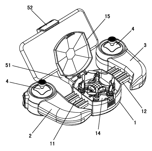
Toys & Games
Stretch-to-Fit Toy Remote with Drone Storage
Toy drone remote with slide-out handles for any hand size, a phone clamp and built-in drone storage.
Patent CN205412243U
Toys & Games
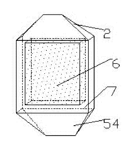
Magnetic Tile Racks for Ultra-Thin Travel Mahjong
Magnetic rack frames that hold ultra-thin mahjong tiles upright and fold into the set's carrying box.
Patent CN207169017U
Toys & Games
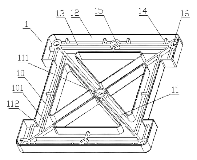
X-Braced Square Magnetic Building Tile with Locating-Post Shell
Square magnetic building tile: open X-brace frame, corner-lug magnets, two shells aligned by posts.
Patent CN105963988B
Toys & Games
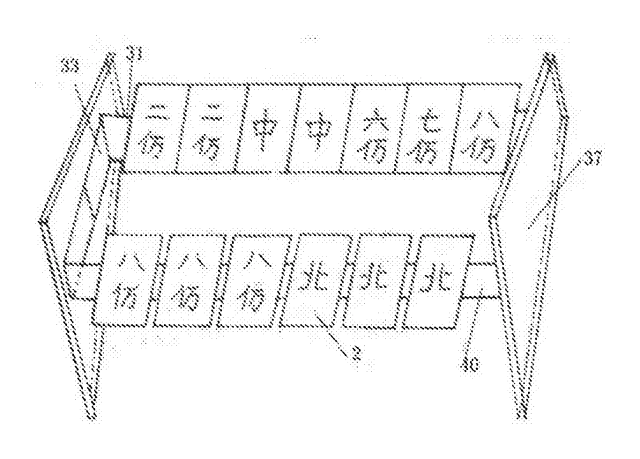
Card-Thin Magnetic Travel Mahjong and Chess Sets with Magnet Racks
Pocket mahjong and chess sets: thin magnetic-powder tiles, finger magnet picker and fold-out magnetic racks.
Patent CN206896783U
Toys & Games
Inflatable Baby Climbing Mat with a Bumpy Hump and a Ramp Obstacle
Inflatable crawling mat: a bumpy rounded hump and a sloped ramp on a stiffened air base.
Patent CN108905229B
Toys, Games & Puzzles
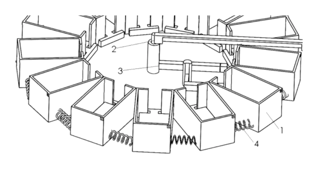
Ring-Layout Automatic Card Shuffler with Electromagnetic Box Coupling
Ring-layout card shuffler that sweeps stacks between boxes via electromagnetic coupling.
Patent CN209564602U
Browse by category
- Apparel & Accessories (49)
- Baby & Kids (29)
- Bags & Luggage (17)
- Bath & Personal Care (32)
- Car Accessories (25)
- Furniture, Bedding & Storage (25)
- Garden & Outdoor (34)
- Health & Wellness (14)
- Home, Kitchen & Cleaning (51)
- Lighting (23)
- Packaging & Containers (12)
- Pet Products (12)
- Phone & Camera Accessories (9)
- Retail Display (25)
- School, Office & Art (37)
- Sports & Recreation (47)
- Tools & Workshop (55)
- Toys & Games (23)
This page is based on the public patent document CN114210074B, assigned to Individual. IP2M is an independent manufacturing service and is not affiliated with, endorsed by or licensed by the patent owner. Images marked as concept renderings are illustrations, not photos of an existing product. Patent status information is provided for reference only and is not legal advice; confirm freedom to operate for your market before production. Full disclaimer.