
Patent CN114508708B
Updated October 31, 2026Multifunctional Solar LED Garden Lamp with Detachable Lantern Body
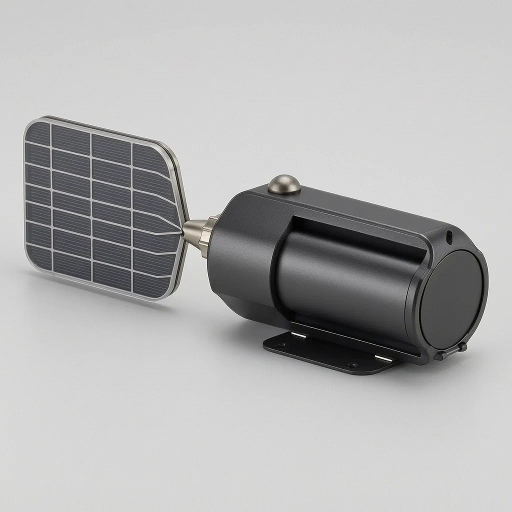
Standard solar path lights are fixed in place; if you need to move them indoors during bad weather or take them camping, you have to buy separate equipment. This design solves that by integrating a detachable lantern into a solar charging base. The LED lamp body sits in a cavity on the charging seat, secured by a magnetic mechanism that releases when needed. At the top, a universal head holds solar panels on rotary joints, allowing them to tilt toward the sun for efficient charging. Once charged, the user simply detaches the LED body to carry it anywhere, turning a garden fixture into a portable emergency light or party lantern.
- China invention patent - active
- Filed only in China
- Solar outdoor lighting
- Magnetic detachable mechanism, adjustable PV array
Splat! What let you down?
🔦
Detachable Lantern
The LED body lifts out of the base to serve as a portable handheld or hanging light.
☀️
Adjustable Solar Head
Rotary joints allow the solar panels to tilt and track sunlight for better charging.
🧲
Magnetic Release
A gear-driven swinging rod mechanism secures the lamp magnetically but allows quick removal.
👁️
Integrated Sensor
Side-mounted sensors enable automatic activation based on environmental conditions.
Bring this product to market
- ✓ Patent vetted China-only family and legal status checked
- 2 Product brief · now How it works, uses and options written up
- 3 Prototype First samples for buyers to review
- 4 Pilot run Small first batch for launch customers
- 5 Volume production Repeat orders at scale
Buyer interest
– of 100 buyers needed to start prototyping
One click, no sign-up. Each vote is one real visitor, and products with the most interest go to prototyping first.
Build team: no members yet. Need a partner, co-funding or skills to build this? Join and we introduce the team once it forms.
The problem
Most solar garden lights are single-purpose fixtures. They stand in the yard all day and night, but if a storm approaches, they must be stored inside separately, or if you want to move the light to a patio table or take it camping, you cannot because the battery and solar panel are permanently housed together in a small unit. Additionally, fixed solar panels often fail to capture optimal sunlight due to changing angles throughout the day, leading to inefficient charging. Users typically need two different products: a stationary garden stake light and a portable rechargeable lantern, which increases cost and storage space.
The solution
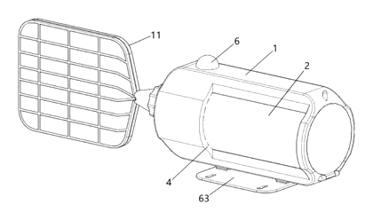
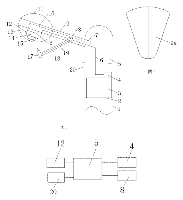
- Charging Seat Structure: The base consists of a charging seat (1) with a middle matching cavity (3) designed to hold the LED lamp main body (2). A light outlet (4) is positioned on the wall outside the cavity to emit light when the body is docked.
- Universal Head and Solar Module: One end of the charging seat features a universal head (65). Attached to this is a solar module (5) comprising traction rods (9), springs (66), and rotary joints (10). These joints connect to fixed brackets (11) holding solar cell panels (12).
- Adjustability Mechanism: The solar panels can be adjusted via the rotary joints within U-shaped grooves (13), allowing the angle of the panels to change relative to the sun. Clamping grooves (14) secure the joint positions.
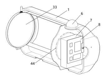
- Magnetic Attachment System: The LED body attaches to the seat using a magnetic attraction separation mechanism. This includes bevel gears (15, 16), driving gears (18), and swinging rods (17) inside the seat’s end part.
- Sensor Integration: An integrated sensor (6) is mounted on the side wall of the charging seat, working with internal power supplies (7) and control boards (8) to manage operation.
- Dual Functionality: When docked, the device acts as a garden light powered by the solar head. When the swinging rods disengage the magnets, the LED body can be lifted out and used independently as a lantern.
Who it is for
- Outdoor Lighting Brands: Companies looking to differentiate their solar product lines with dual-use functionality (garden + portable).
- Camping and Hiking Gear Retailers: Sellers who can market this as both a campsite perimeter light and a personal tent lantern.
- Emergency Preparedness Suppliers: Distributors offering home backup lighting solutions that charge automatically in the yard but store indoors easily.
- Garden Center Chains: Retailers selling decorative path lights that offer added value through portability and adjustable solar efficiency.
How it works
The main parts
| No. | Part | What it does |
|---|---|---|
| 1 | Charging Seat | Base structure housing electronics and mechanical locks. |
| 2 | LED Lamp Body | Portable light unit that docks into the seat. |
| 3 | Matching Cavity | Space in the seat where the LED body fits. |
| 4 | Light Outlet | Window allowing light emission when docked. |
| 5 | Solar Module | Assembly including panels, brackets, and adjustment joints. |
| 6 | Integrated Sensor | Detects environment (e.g., darkness/motion) to trigger light. |
| 7 | First Power Supply | Internal battery/power management unit. |
| 8 | Control Mainboard | Electronic circuit managing charging and output. |
| 9 | Traction Rod | Structural arm connecting the solar head to the seat. |
| 10 | Rotary Joint | Pivot point allowing solar panel angle adjustment. |
| 11 | Fixed Bracket | Holder for the solar cell panels. |
| 12 | Solar Cell Panel | Photovoltaic surface converting sunlight to electricity. |
| 15, 16 | Bevel Gears | Transmission components for the locking mechanism. |
| 17 | Swinging Rod | Mechanical lever engaging/disengaging the magnetic lock. |
| 27 | Magnetic Attraction Device | Magnet securing the LED body to the seat. |
Operating Steps
- Docking: Insert the LED lamp body (2) into the matching cavity (3) of the charging seat (1). The magnetic attraction device (27) engages with the body’s metal interface.
- Locking: The swinging rods (17) extend into slots (28) on the universal head/seat interface, stabilized by the bevel gear system (15, 16), ensuring the connection is secure against wind or vibration.
- Adjustment: Manipulate the rotary joints (10) to tilt the solar panels (12) toward the sun. The spring (66) and traction rod (9) provide tension and support.
- Charging: Sunlight hits the panels (12), generating current managed by the control board (8) and stored in the power supply (7).
- Detachment: To use as a lantern, release the mechanical lock (via specific interaction not fully detailed in claims but implied by “separation mechanism”), lift the LED body (2) out of the cavity (3).
- Portable Use: Carry the detached LED body (2) independently. It operates on its own battery, controlled by the integrated sensor (6) or manual switch.
Applications
Backyard Path Lighting
Users install multiple units along walkways. During the day, the adjustable solar heads maximize charging. At night, they function as standard path lights. If guests arrive, the host can detach several bodies to create ambient lighting on tables or patios without moving the heavy bases.
Camping and Outdoor Events
Campers leave the bases anchored in the ground to charge throughout the day. In the evening, they detach the LED bodies to hang inside tents or carry on hikes. This reduces the weight carried into the campsite initially, as only the lightweight lanterns are moved.
Emergency Home Backup
Homeowners place these in gardens year-round. In case of a power outage, the units are already charged. Residents can quickly grab the LED bodies to illuminate hallways or rooms indoors, then return them to the bases when power is restored for recharging.
Agricultural or Farm Perimeters
Farm managers use these for security lighting around barns or fences. The motion-sensing capability (implied by integrated sensor) saves battery life. Workers can detach a light to inspect livestock or equipment in dark corners, carrying the portable unit back to the station afterward.
Where it is less suitable
- High-Wind Coastal Areas: While the magnetic lock is robust, extremely high winds might stress the adjustable solar head if not properly angled or locked tight.
- Heavy Industrial Sites: The plastic/lightweight construction typical of consumer garden lamps may not withstand harsh industrial environments compared to ruggedized metal fixtures.
- Permanent Indoor Installation: Since the solar component requires sunlight, this device is inefficient if the base is kept indoors permanently; it is designed for outdoor docking.
Frequently asked questions
How does the LED body detach from the base?
The patent describes a magnetic attraction separation mechanism. Inside the charging seat, there are swinging rods driven by bevel gears. When engaged, these rods lock into slots on the universal head or interface, securing the magnetic connection. To detach, the mechanism is released (likely via a button or lever action implied by the “adjusting rod” and “driving gear”), allowing the LED body to be lifted out easily.
Can the solar panels really adjust?
Yes. The solar module uses rotary joints and fixed brackets attached to a traction rod. This allows the angle of the solar panels to be changed manually to face the sun directly, improving charging efficiency compared to fixed-panel lights.
Is the light waterproof?
The patent does not specify an IP rating. However, the design includes sealed cavities and external walls. For US sales, we recommend targeting an IP65 rating to ensure protection against rain and dust. Specific sealing methods (gaskets, ultrasonic welding) are determined during the engineering phase.
How long does the battery last?
The patent mentions a “first power supply device” but does not give a capacity in mAh or hours. Battery life depends on the chosen cell size and LED lumen output. We can customize the battery capacity to meet specific runtime requirements (e.g., 8 hours, 12 hours) in the design phase.
Does it have a motion sensor?
The patent includes an “integrated sensor” on the side wall. This is typically a PIR (Passive Infrared) motion detector or a photocell. You can choose the sensor type during customization. Motion detection helps save battery by turning the light on only when movement is detected.
Can I use the lantern indoors?
Yes. Once detached from the charging seat, the LED lamp main body functions as a standalone portable lantern. It has its own battery and controls, so it can be used inside homes, tents, or garages without being connected to the solar base.
Can this design be made and sold in the US?
The patent is filed only in China and is currently in force there. It has no US counterpart. Therefore, selling this design in the US does not infringe on this specific Chinese patent. However, because solar lights are a crowded field, we strongly recommend a freedom-to-operate (FTO) search to check for any existing US patents that might cover similar magnetic release mechanisms or adjustable solar structures.
Are you affiliated with the patent owner?
No. IP2M is an independent design and manufacturing service working from the public patent document. We do not represent Shenzhen Ako Photoelectric Technology Co ltd.
Request a quote
Click Request a Quote below to see our email address - copy it, or open your email app with a ready-made message. Please mention patent CN114508708B in the subject.
Helpful details to include:
- Your company and channel (outdoor lighting brand, camping gear retailer, home improvement chain)
- Target specs (lumens, battery capacity, solar panel wattage)
- Features (motion sensor type, timer settings, USB charging option)
- Materials (plastic type, finish preferences)
- Estimated quantity and target price
- Timeline - when you would like samples and the first shipment
You can also reach us at (332) 203-9997.
Explore this product
Interested in building this?
Tell us your target market, quantity and timeline. We reply with options for prototyping, small-batch runs or volume production.
Send your inquiry to
Please put CN114508708B in the subject line and tell us your company, country, estimated quantity and timeline.
Prefer to talk? Call (332) 203-9997.
More product-ready patents
All Lighting patents →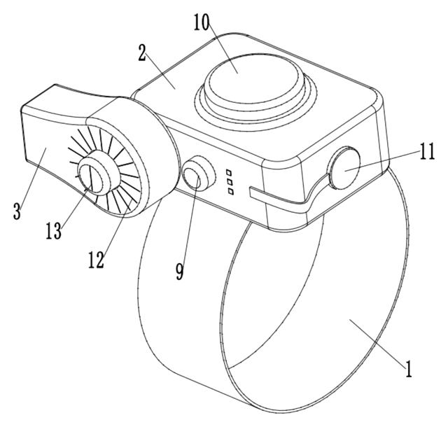
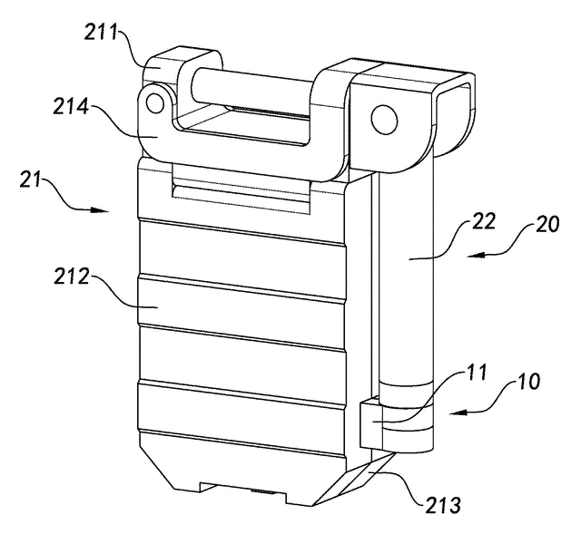
Lighting
Wrist-Worn Flashlight with Click-Lock Angle Adjustment
Rechargeable wrist flashlight whose lamp turns and locks at an angle with a push button.
Patent CN113915544B
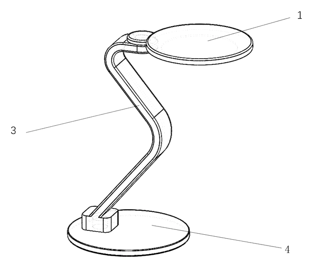
Lighting
Self-Folding Desk Lamp That Turns into a Phone Stand
Desk lamp with a shape-memory stem that unfolds when warm and folds into a phone stand.
Patent CN213237087U
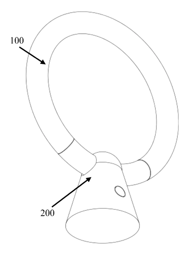
Lighting
Ring-Shaped Outdoor Lantern That Lifts Off a Power-Bank Charging Base
Ring lantern with a battery handle that docks in a cone base with its own battery, clamp and charging plug.
Patent CN212408329U
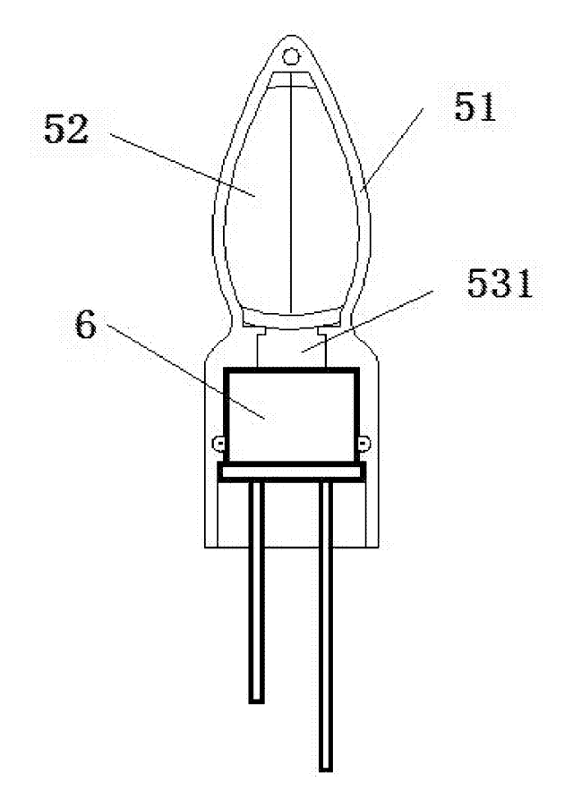
Lighting
LED Flameless Candle with an Outside Flame Shade and Wax Dish Top
Battery LED candle: flame shade stands above a dished wax top, angled LEDs light a printed wick.
Patent CN205424561U
Lighting
Telescoping Tripod Portable Work Light with Fold-In Light Panels
Telescoping tripod work light with dual light panels that fold flat into the base.
Patent CN207298471U
Lighting
Self-Cooling and Self-Cleaning LED Street Light with Rainwater Harvesting
LED street lamp that harvests rain to cool its heat sink and spray-wash the lens automatically.
Patent CN205480639U
Browse by category
- Apparel & Accessories (25)
- Baby & Kids (18)
- Bags & Luggage (12)
- Bath & Personal Care (18)
- Car Accessories (14)
- Furniture, Bedding & Storage (13)
- Garden & Outdoor (21)
- Health & Wellness (9)
- Home, Kitchen & Cleaning (28)
- Lighting (14)
- Packaging & Containers (7)
- Pet Products (6)
- Phone & Camera Accessories (5)
- Retail Display (15)
- School, Office & Art (21)
- Sports & Recreation (27)
- Tools & Workshop (32)
- Toys & Games (14)
This page is based on the public patent document CN114508708B, assigned to Shenzhen Ako Photoelectric Technology Co ltd. IP2M is an independent manufacturing service and is not affiliated with, endorsed by or licensed by the patent owner. Images marked as concept renderings are illustrations, not photos of an existing product. Patent status information is provided for reference only and is not legal advice; confirm freedom to operate for your market before production. Full disclaimer.