
Patent CN114652109B
Updated October 27, 2026Rotary Storage Basket with Elastic Positioning for Cabinets
Standard turntables inside deep cabinets often spin too freely. A quick push sends them turning past the items you need, forcing you to grab the edge and brake them by hand. This rotary storage basket solves that problem with a built-in positioning system. A rotary positioning disc sits at the bottom of the storage rack or the support part, featuring arc-shaped elastic guide positioning parts arranged around the rotation axis. A matching positioning piece on the opposite part has an arc-shaped convex surface. As you turn the rack, the positioning piece touches and presses the elastic guides. They deform just enough to let the piece pass, then spring back under their own elastic force to catch the piece in a clamping area between two guides. The rack stops exactly where it should, without overshooting. Because the elastic guides absorb the movement, you only need a small turning force to switch positions rather than a large push followed by manual braking. The design keeps stored items accessible and stable inside corner base units, pantries, or bathroom vanities.
- China invention patent - in force
- No filings outside China
- Cabinet & furniture hardware
- POM plastic or metal elastic guides
Splat! What let you down?
🔄
Set-angle positioning
Elastic guides and a positioning piece click the rack into place, preventing free inertia spin.
🧩
Flexible disc mounting
The rotary positioning disc mounts on the storage rack bottom or the rotary support part.
🌿
Material options
Guides can be integrally injection-molded POM or metal parts fixed by secondary molding or fasteners.
↩️
S-shaped support
An S-shaped elastic supporting member behind the guides maintains elastic strength and positioning effect.
Bring this product to market
- ✓ Patent vetted China-only family and legal status checked
- 2 Product brief · now How it works, uses and options written up
- 3 Prototype First samples for buyers to review
- 4 Pilot run Small first batch for launch customers
- 5 Volume production Repeat orders at scale
Buyer interest
– of 100 buyers needed to start prototyping
One click, no sign-up. Each vote is one real visitor, and products with the most interest go to prototyping first.
Build team: no members yet. Need a partner, co-funding or skills to build this? Join and we introduce the team once it forms.
The problem
Inside deep or corner cabinets, reaching items at the back requires pulling everything out or installing a turntable. Basic turntables spin freely on a central shaft. When a user pushes the edge to reach a jar at the back, the platform often rotates past the desired spot due to inertia. The user must then grab the rim to brake it manually. Over time, heavy loads make the free-spinning action harder to control, and items shift or fall when the platform does not stop predictably. Adding external friction brakes or detent springs increases the parts count and assembly steps for cabinet makers.
The solution
This design integrates the stopping mechanism directly into the rotating assembly.
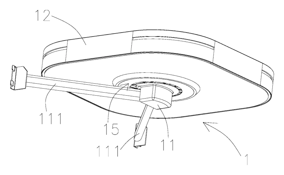
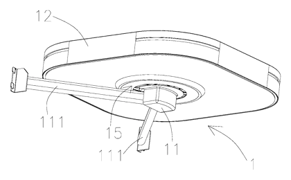
- A storage rack (12) is rotatably connected to a rotary support part (11), allowing the user to turn the rack to access items at different positions.
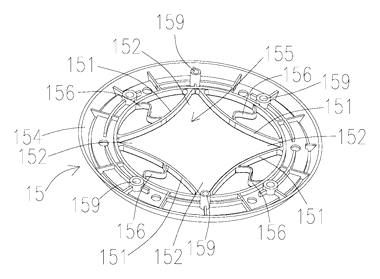
- A rotary positioning disc (15) is mounted either at the bottom of the storage rack or on the rotary support part. It contains a disc body (154) with a central space (155).
- Around the rotation axis, multiple elastic guide positioning parts (151) protrude inward in an arc shape. A positioning clamping area (152) is formed between every two adjacent guides.
- A positioning piece (14) is installed on the opposite component (the support part if the disc is on the rack, or the rack if the disc is on the support). It features an arc-shaped convex positioning surface (142) shaped to match the guides.
- When the rack is turned, the positioning surface touches and presses the elastic guide. The guide deforms elastically, allowing the surface to pass its middle point. Once past, the elastic force of the guide snaps the positioning piece into the next clamping area, locking the rack at a set angle.
Who it is for
- Kitchen cabinet manufacturers needing a predictable turntable for corner base units or pantry columns where users store jars and cans.
- Bathroom vanity brands looking for a rotating organizer that stops firmly so bottles do not tip when the tray spins.
- Closet and wardrobe system makers adding rotating accessory trays for ties, belts, or folded clothes inside deep compartments.
- Hardware component suppliers sourcing a self-contained rotating mechanism to sell as an upgrade kit for existing cabinet frames.
How it works
The main parts
| No. | Part | What it does |
|---|---|---|
| 11 | Rotary support part | Fixed base that holds the rotating assembly; carries the positioning piece or disc. |
| 12 | Storage rack | Holds the items; rotates on the support part via bearings. |
| 14 | Positioning piece | Features an arc-shaped convex surface that engages the elastic guides. |
| 15 | Rotary positioning disc | Holds the elastic guides and forms the clamping areas. |
| 151 | Elastic guide positioning part | Arc-shaped inward protrusions that deform and spring back to lock the rack. |
| 152 | Positioning clamping area | The gap between two guides where the positioning piece rests. |
| 154 | Disc body | The main plate of the positioning disc containing the central space. |
| 155 | Central space | The open area in the disc body where the guides are arranged. |
| 156 | Elastic supporting member | An S-shaped support between the guide and the clearance area wall to maintain elastic strength. |
Operating steps
- Turn the rack - The user applies a small rotational force to the storage rack.
- Deform the guide - The positioning piece’s convex surface presses against the elastic guide positioning part, causing it to deform outward into the clearance area.
- Pass the center - Once the middle of the positioning surface passes the middle of the elastic guide, the guide begins to spring back.
- Snap into place - The elastic force drives the positioning piece into the next positioning clamping area. The rack stops at the set angle without overshooting.
Applications
Kitchen corner cabinets
Corner base cabinets leave deep, unreachable spaces. A rotating rack with four clamping areas allows the user to turn the basket 90 degrees per click, bringing spices or canned goods from the back directly to the cabinet opening without continuous spinning.
Pantry pull-outs
Tall pantry units use rotating shelves to maximize vertical storage. The elastic positioning prevents heavy jars from swinging the shelf past the intended stop, keeping the contents stable during rotation.
Bathroom vanity organizers
Vanity cabinets hold tall bottles that tip easily. The positioning disc ensures the tray locks firmly after each turn, so users can select toiletries without holding the tray steady with one hand.
Wardrobe accessory trays
Deep closets use rotating trays for folded garments or accessories. The set-angle clicks allow the user to index through sections quickly, finding specific items without rotating the entire tray aimlessly.
Retail display fixtures
Countertop displays in shops benefit from controlled rotation. The elastic guides keep the display facing the customer at fixed intervals, making product reading easier while allowing shoppers to turn it smoothly.
Where it is less suitable
- Heavy industrial shelving - the plastic or slender metal guides are sized for household and light commercial cabinet loads, not warehouse pallet weights.
- Continuous lazy susans - applications requiring smooth, unbroken 360-degree rotation without tactile stops will find the clamping action intrusive.
- Outdoor exposed environments - unless sealed or made of specific weather-resistant materials, the slender elastic structures may degrade if exposed to constant moisture or UV.
Frequently asked questions
How does the basket stop spinning?
A rotary positioning disc contains arc-shaped elastic guides. A positioning piece on the rotating part presses against these guides when turned. The guides deform slightly to let the piece pass, then spring back to trap it in a clamping area between two guides, locking the basket at a set angle.
Does it click every 90 degrees?
The patent describes an embodiment with 4 elastic guides forming 4 clamping areas, which positions a square rack every 90 degrees. Different numbers of guides can be set in design for other angles.
What are the elastic guides made of?
They can be integrally injection-molded with the disc as slender POM plastic structures. Alternatively, they can be metal pieces fixed to the disc by secondary injection molding, fasteners, or a clamping connection.
Will the plastic guides break over time?
The design includes a clearance area behind each guide and an S-shaped elastic supporting member connecting the guide to the side wall. These features maintain the elastic strength and positioning effect. Exact cycle life is confirmed on prototypes.
Can this fit inside a standard corner cabinet?
Yes. The patent describes a storage cabinet where the rotary support is fixed on a bracket inside the cavity, with the rotation center positioned in the middle of the cabinet. Dimensions are set in design to match specific cabinet sizes.
Is the turntable hard to push?
No. Because the elastic guides deform to release the positioning piece, the user only needs to apply a small rotational driving force to move to the next clamping area, rather than pushing hard and braking manually.
Can this design be made and sold in the US?
The patent was filed only in China and is currently in force there. It has no US counterpart, so it does not restrict making or selling the design in the US. However, other US patents may cover similar rotary cabinet mechanisms - see Patent & Production - so we recommend a freedom-to-operate check before volume production.
Are you affiliated with the patent owner?
No. IP2M is an independent design and manufacturing service working from the public patent document.
Request a quote
Click Request a Quote below to see our email address - copy it, or open your email app with a ready-made message. Please mention patent CN114652109B in the subject.
Helpful details to include:
- Your company and channel (cabinet maker, closet brand, hardware supplier, Amazon seller)
- Basket shape and size (diameter, square footprint, tier count)
- Preferred materials (POM disc, metal wire rack, etc.)
- Number of positioning angles required
- Estimated quantity and target price
- Timeline - when you would like samples and the first shipment
You can also reach us at (332) 203-9997.
Explore this product
Interested in building this?
Tell us your target market, quantity and timeline. We reply with options for prototyping, small-batch runs or volume production.
Send your inquiry to
Please put CN114652109B in the subject line and tell us your company, country, estimated quantity and timeline.
Prefer to talk? Call (332) 203-9997.
More product-ready patents
All Furniture, Bedding & Storage patents →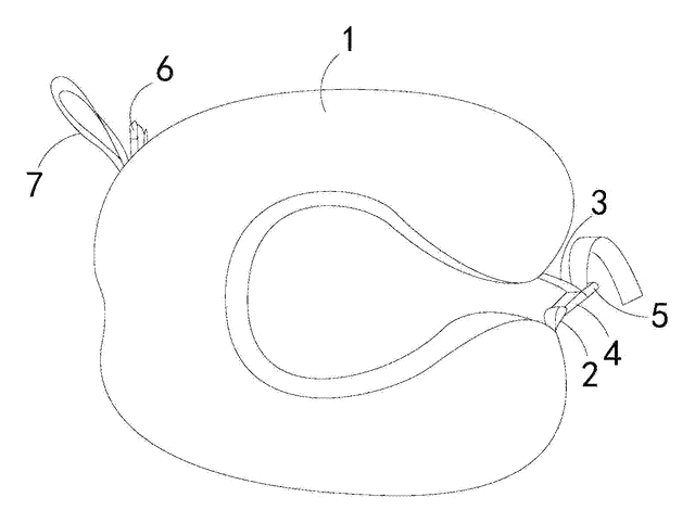
Furniture, Bedding & Storage
Roll-Up Travel Neck Pillow with Buckles
U-shaped travel pillow with a front buckle and a back buckle that holds it rolled up for carrying.
Patent CN206543091U
Furniture, Bedding & Storage
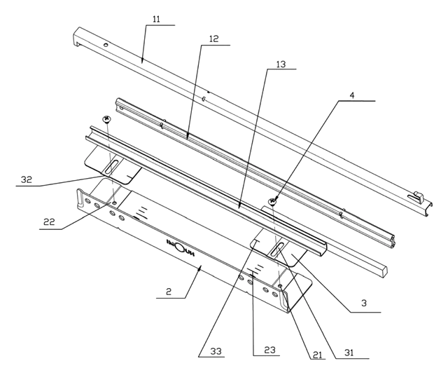
Width-Adjustable Slide Rail for Pull-Out Baskets
Basket slide rail on a slotted, scaled adjusting plate, so one pull-out basket fits several cabinet widths.
Patent CN208909382U
Furniture, Bedding & Storage
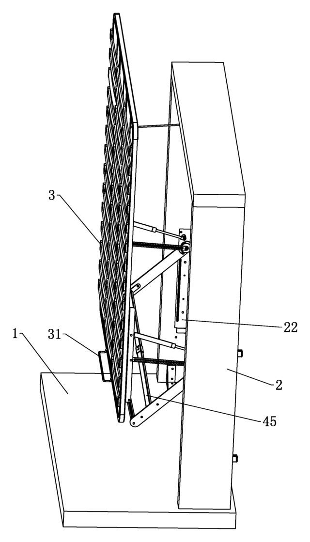
Lift-Up Storage Bed with Four-Bar Linkage That Slides the Deck Away from the Headboard
Storage bed deck that rises on four-bar linkages and gas springs, clearing the headboard as it opens.
Patent CN210870645U
Furniture, Bedding & Storage
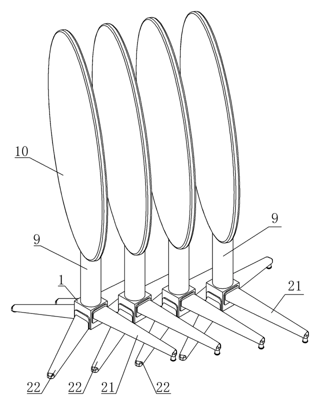
Self-Leveling, Nesting Table Base with a Torsion-Ring Leg Hub
Four-leg base that self-levels through a torsion-ring hub and nests sideways with flip-top tables.
Patent CN211483640U
Furniture, Bedding & Storage
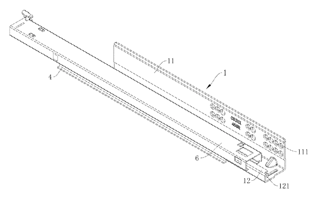
Rack-and-Pinion Synchronized Drawer Slide with a Folded-In Fixed Rail
Full-extension drawer slide: a pinion between two racks keeps the rails moving in step.
Patent CN206314843U
Furniture & Bedding
Dual-Zone Split-Spring Mattress with Removable Fabric Cover
Half-pocket, half-standard spring mattress sharing one base plate, with a removable cover.
Patent CN208355064U
Browse by category
- Apparel & Accessories (22)
- Baby & Kids (16)
- Bags & Luggage (9)
- Bath & Personal Care (16)
- Car Accessories (10)
- Furniture, Bedding & Storage (12)
- Garden & Outdoor (18)
- Health & Wellness (8)
- Home, Kitchen & Cleaning (24)
- Lighting (12)
- Packaging & Containers (6)
- Pet Products (6)
- Phone & Camera Accessories (4)
- Retail Display (13)
- School, Office & Art (19)
- Sports & Recreation (25)
- Tools & Workshop (27)
- Toys & Games (12)
This page is based on the public patent document CN114652109B, assigned to Guangdong Bangao Home Technology Co ltd. IP2M is an independent manufacturing service and is not affiliated with, endorsed by or licensed by the patent owner. Images marked as concept renderings are illustrations, not photos of an existing product. Patent status information is provided for reference only and is not legal advice; confirm freedom to operate for your market before production. Full disclaimer.