
Patent CN114987093B
Updated November 5, 2026Mechanical Automatic Pencil Sharpener with Integrated Storage
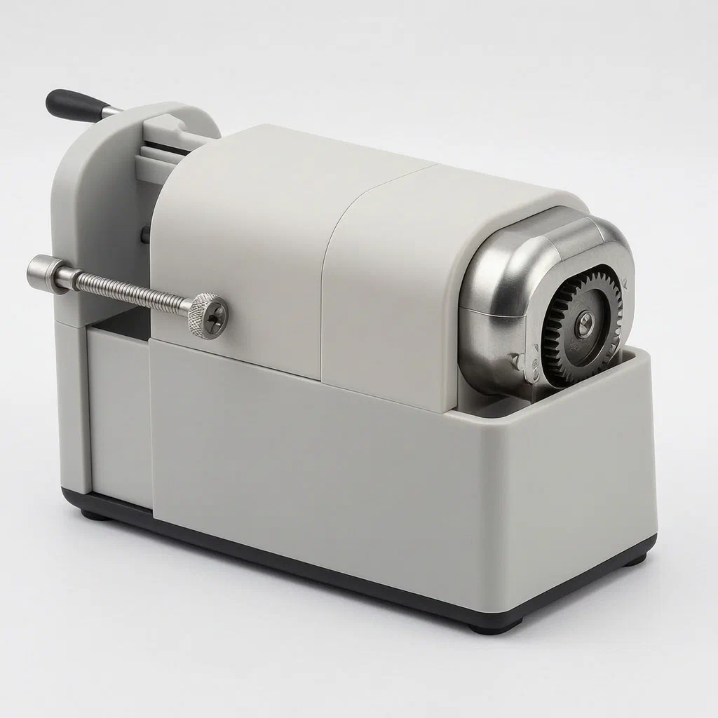
Traditional electric sharpeners require batteries or cords, while manual ones demand constant hand motion. This mechanical design bridges the gap. A simple pull-and-release action on a tension plate engages a spiral crankshaft connected to a transmission shaft. This shaft drives both the cutting tool rest and the dual-shaft pencil clamp. The result is automatic synchronization: as the blades rotate to cut, the clamping shafts advance the pencil forward; reversing the action retracts it. An internal adjusting rod allows users to set the exact length and thickness of the pencil tip by changing how far the cutter head extends. The base unit doubles as a storage rack for stationery, keeping the workspace tidy without needing separate containers.
- China invention patent - active
- No filings outside China
- Mechanical spring drive
- Adjustable blade depth
Splat! What let you down?
🔄
Auto-Feed Mechanism
A spring-loaded crankshaft automatically advances and retracts the pencil during cutting.
✏️
Adjustable Tip Size
An internal sliding rod controls blade exposure to customize point length and thickness.
📦
Integrated Storage
The base rack holds the sharpener and stores erasers or extra pencils when not in use.
⚙️
Synchronized Gearing
Interlocking gears ensure the cutting tool and feeding shafts move in perfect step.
Bring this product to market
- ✓ Patent review Patent family and legal status reviewed in the relevant jurisdictions.
- 2 Product brief · now How it works, uses and options written up
- 3 Prototype First samples for buyers to review
- 4 Pilot run Small first batch for launch customers
- 5 Volume production Repeat orders at scale
Buyer interest
– of 100 buyers needed to start prototyping
One click, no sign-up. Each vote is one real visitor, and products with the most interest go to prototyping first.
Build team: no members yet. Need a partner, co-funding or skills to build this? Join and we introduce the team once it forms.
Patent Rights & Team Participation
Before joining a development team, participants should ensure they have the necessary rights or authorization to participate in the project.
Participation is generally appropriate where:
- You own the relevant patent rights or have obtained permission or a license from the rights holder.
- The relevant patent rights have expired or have been legally invalidated in the jurisdictions where the planned activities will take place.
- The planned development, manufacturing, and commercialization activities have been independently assessed and do not infringe applicable patent rights in the relevant jurisdictions.
Important: Being located outside a country where a patent is protected does not automatically exempt you from patent infringement risks. Patent rights may apply based on where development, manufacturing, use, sale, or import activities take place.
IP2M does not grant any patent license or authorization through team participation. Joining a project does not provide permission to use, manufacture, or commercialize patented technology.
The problem
Manual pencil sharpeners require continuous hand effort, leading to fatigue and inconsistent points. Electric models need power sources and often jam if the pencil diameter varies slightly. Users frequently struggle to achieve specific tip shapes—such as long, thin drafting points versus short, blunt writing points—without specialized tools. Additionally, standalone sharpeners clutter desks and lack storage for the shavings or accompanying accessories like erasers. There is a need for a battery-free device that automates the feeding process, allows precise control over the sharpened geometry, and integrates neatly into a desktop organizer.
The solution
This design replaces electrical components with a purely mechanical system driven by potential energy stored in a tension spring.
- Tension Plate and Spring: A user pulls a tension plate outward, stretching a tension spring. Releasing the plate causes the spring to reset, driving a spiral crankshaft.
- Transmission Shaft: The crankshaft rotates a central transmission shaft, which acts as the primary power distributor.
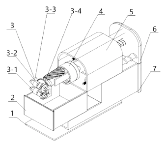
- Cutting Mechanism: The shaft connects to an adapter holding a tool fixing frame. Inside this frame, a cylindrical tool bit (blade) rotates against a stationary tool rest.
- Feeding Mechanism: Simultaneously, the shaft drives two parallel clamping shafts equipped with gears. These shafts grip the pencil and push it forward into the rotating blades.
- Retraction: When the user pulls the tension plate again, the system reverses, withdrawing the sharpened pencil from the cutter.
- Storage Rack: The entire assembly sits within a rack structure that can be pulled out to store stationery items.
Who it is for
- School Supply Brands looking for durable, battery-free alternatives to cheap plastic sharpeners that break easily.
- Art and Drafting Suppliers whose customers need precise control over pencil tip length and thickness for technical drawings.
- Office Stationery Retailers seeking compact desk organizers that combine sharpening functionality with storage for erasers and clips.
- Educational Institutions requiring safe, low-maintenance tools for classrooms where electrical outlets may be scarce or unsafe for young children.
How it works
The main parts
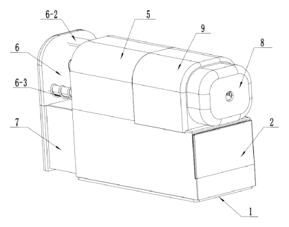
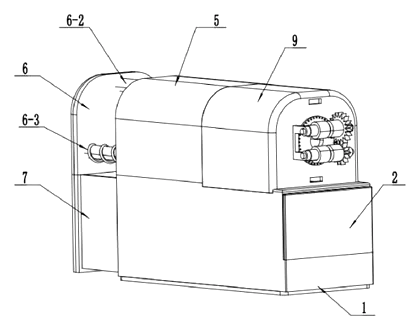
The device consists of four interconnected subsystems: the drive, the cutter, the feeder, and the housing.
| No. | Part | What it does |
|---|---|---|
| 6-5 | Tension Plate | User interface; pulling it stretches the spring. |
| 6-3 | Tension Spring | Stores energy to drive the return stroke. |
| 6-4 | Spiral Crankshaft | Converts linear spring movement into rotation. |
| 6-1 | Transmission Shaft | Distributes rotation to both cutting and feeding parts. |
| 4-1 | Tool Rest | Holds the pencil steady relative to the blade. |
| 4-2 | Tool Bit | Rotating cylindrical blade that cuts the wood/graphite. |
| 3-1/3-2 | Clamping Shafts | Two geared shafts that grip and advance the pencil. |
| 3-4 | Driving Disc | Connects the feed mechanism to the main shaft. |
| 7 | Storage Box | Pull-out compartment for stationery. |
Operating Steps
- Setup: The user adjusts the internal rod to set the desired blade exposure. Longer exposure creates shorter, thicker tips; shorter exposure creates longer, thinner tips.
- Insertion: The pencil is placed between the two clamping shafts.
- Activation: The user pulls the tension plate outward. This compresses the spring but does not yet sharpen.
- Sharpening Cycle: Upon releasing the plate, the spring snaps back. The spiral crankshaft rotates the transmission shaft.
- The shaft turns the tool bit, causing it to spin against the wood.
- The same shaft rotates the clamping shafts. Because they are geared together, they turn in opposite directions, gripping the pencil and pushing it forward into the spinning blade.
- Completion: Once the pencil reaches the stop position or is fully advanced, the cycle ends.
- Retraction: To remove the pencil, the user pulls the tension plate again. This reverses the gear ratio or simply disengages the feed, allowing the pencil to be withdrawn manually or via reverse rotation depending on the specific latch state described in the claims.
- Storage: When not in use, the sharpener unit can be stowed inside the pull-out rack along with erasers.
Applications
Classroom Desks
Teachers prefer this model because it requires no electricity, reducing safety hazards and maintenance costs. Students learn to operate a mechanical device, and the synchronized feed prevents pencils from breaking due to uneven pressure, a common issue with manual sharpeners.
Artist Studios
Draftsmen and artists need consistent line weights. The adjustable blade exposure allows them to switch between broad shading pencils and fine detail liners without changing tools. The quiet operation compared to motorized units helps maintain focus during long work sessions.
Home Offices
For individuals who write occasionally, this device serves as a tidy desk accessory. The integrated storage rack keeps erasers and spare leads organized, preventing clutter. Its compact footprint fits well on crowded desks where space is limited.
Retail Display Units
Stationery shops can demonstrate the product’s ease of use directly on the sales floor. Customers can test the “pull and release” action instantly, understanding the value proposition without needing batteries or instructions. The visible mechanism appeals to those interested in mechanical engineering or gadgetry.
Where it is less suitable
- High-Volume Industrial Use: This manual spring-drive mechanism is slower than electric commercial sharpeners used in large schools or factories.
- Very Large Diameter Pencils: The clamping shaft gap is fixed by design; extremely thick carpenter pencils may not fit without modification.
- Outdoor Environments: The intricate gear train and spring are susceptible to dust and grit, which could jam the mechanism if not protected by a cover.
Patent & Production
At a glance
| Patent number | CN114987093B (application CN202210653154) |
| Type | China invention patent (发明专利) - protects method and structure |
| Original title | A Multifunctional Convenient Pencil Sharpener (一种多功能便捷削铅笔刀) |
| Patent owner | Kunming University of Science and Technology |
| Inventors | Chen Ming, Zhu Hailong, Xia Wensheng, Li Guance |
| Filing date | 2022-06-10 |
| Grant date | 2023-11-17 |
| Status (China) | In force - valid until at most 2042-06-10, subject to payment of annual fees |
| Patent family | Public record shows Chinese filings only - no US, European, Japanese, PCT or other filings listed |
| Cited by | 0 later documents |
| Source | Google Patents (search for CN114987093B) |
What the claims cover, in plain language
Claim 1 describes a pencil sharpener comprising a pencil advancing and retreating mechanism, a cutting mechanism, a transmission mechanism, and a rack. The transmission mechanism includes a transmission shaft, telescopic rod, tension spring, spiral crankshaft, and tension plate. The tension plate connects to the rack via the telescopic rod and spring. The spiral crankshaft meshes with the transmission shaft. The cutting mechanism uses a tool rest, tool bit, and tool fixing frame mounted on bearings. The feeding mechanism uses first and second clamping shafts with intermeshing gears and a driving disc. The key feature is that forward motion of the transmission drives the cutting and feeding simultaneously, while reverse motion retracts the pencil.
Claim 2 specifies that the adapter has a second sliding hole containing an adjusting rod. This rod allows adjustment of the cutting length and thickness of the pencil by changing the tool rest’s position relative to the blade.
Claim 3 notes that grooves are formed on the upper surfaces of the first and second clamping shafts in the radial direction at the insertion hole location. These grooves limit the pencil’s lateral movement, ensuring it stays centered while moving back and forth.
This is a simplified reading for orientation only. The legal scope is defined by the exact claim wording in the official Chinese document.
What this means for US production
This patent was filed in China and is currently in force. Making or selling this specific configuration in China would require permission from the patent owner. However, the public record shows no US counterpart or other foreign family members. Therefore, this Chinese patent does not restrict making or selling the product in the United States.
Two points to settle early:
- Other patents may exist. Pencil sharpeners are a mature category with many existing utility and design patents. While this specific spring-crank synchronization is unique to this filing, similar mechanical feed systems might be covered by older or newer US patents held by major stationery manufacturers. A freedom-to-operate (FTO) review focusing on “mechanical auto-feed” and “adjustable blade exposure” is recommended before tooling.
- Design variations. If you modify the drive mechanism (e.g., replacing the spiral crankshaft with a cam system), you may avoid infringement, but must still check for other blocking patents.
Customization and manufacturing
What can be customized
| Area | Options |
|---|---|
| Housing Material | ABS or PP injection molding for durability; aluminum extrusion for premium feel |
| Blade Type | Standard steel cylinder or coated carbide for harder pencils |
| Color/Finish | Matte or glossy finishes; printing of logos on the tension plate or rack |
| Storage Capacity | Depth of the pull-out rack can be adjusted based on mold cavity size |
| Adjustment Range | Length of the sliding rod determines min/max tip sharpness settings |
| Spring Rate | Stiffness of the tension spring affects the “feel” of the pull-and-release action |
Things to plan for (US market)
- ASTM F963 - Toy Safety Standard. If marketed to children under 14, the device must pass tests for sharp edges, small parts, and mechanical hazards.
- CPSC Guidelines - General consumer product safety rules apply regarding pinch points and moving parts.
- California Prop 65 - Plastics and metal coatings must be screened for restricted chemicals.
How a project runs
- Inquiry - Define target price, volume, and material preferences.
- Design - Finalize gear ratios, spring specs, and housing dimensions.
- Prototype - Create 3D-printed samples for fit and function testing.
- Pilot Run - Produce small batch with real molds; test durability and sharpening quality.
- Production - Injection molding, stamping blades, assembling gears/springs, packaging.
Quantities & timeline
Tooling for the housing and gear components takes several weeks. Assembly involves snap-fits and screw fasteners. Certification testing adds time before shipment. Send us your target quantity, material choice, and color requirements and we will reply with options.
Production notes
Tooling and process
The main housing likely requires ABS or PP injection molding to accommodate the complex internal cavities for the gears and shafts. Steel components like the clamping shafts and tool bits typically undergo stamping followed by heat treatment for hardness. The spiral crankshaft may be molded or formed by stamping depending on precision needs.
Cost drivers
Costs are typically driven by the number of molds required for the multi-part housing and internal gears. Assembly steps add labor costs due to the need to align shafts and install springs carefully. Print setup for branding on the exterior also contributes to initial expenses.
Prototyping path
We would typically start with a 3D-printed sample to verify the gear meshing and travel distance of the tension plate. Use off-the-shelf springs to test the reset force. Conduct a function and cycle test to ensure the pencil advances smoothly without jamming before committing to tooling.
What we would change before tooling
We would refine the wall thickness and joint design of the plastic housing to prevent flexing under spring tension. We would also optimize the snap-fit locations to reduce assembly time and improve structural integrity.
Common failure points
Key risks include spring fatigue and rate consistency, which affect the reliability of the auto-reset. Shaft and bearing alignment issues can cause grinding noise or seizure. Sharp edges on stamped blades must be deburred to meet safety standards.
Patent drawings
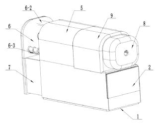
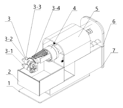
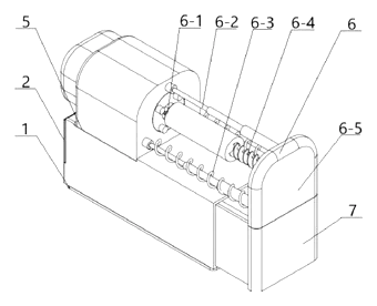
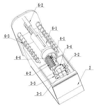
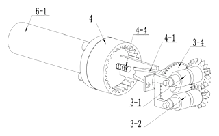
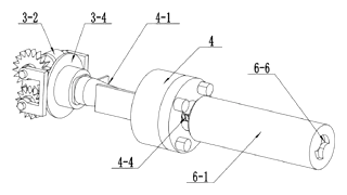
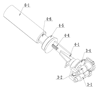
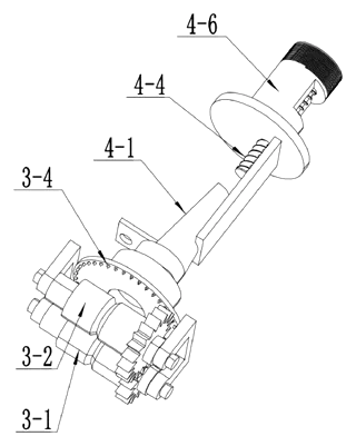
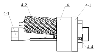
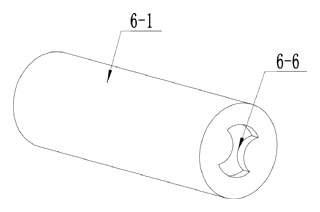
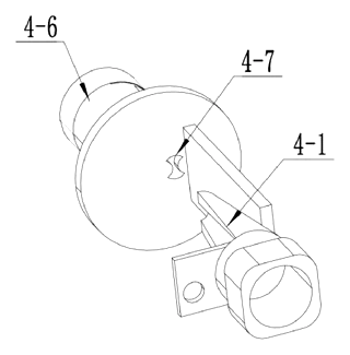
Drawings reproduced from the public patent document for reference.
Frequently asked questions
How does the sharpening start?
You pull a tension plate outward to stretch a spring. When you release it, the spring snaps back, turning a crankshaft. This rotation drives both the cutting blade and the pencil feeder simultaneously.
Can I change the pencil tip shape?
Yes. An internal adjusting rod controls how far the blade sticks out. Extending the blade more creates a shorter, thicker tip; retracting it creates a longer, sharper point. This is set by loosening the casing and sliding the rod.
Does it require batteries or electricity?
No. The device is purely mechanical. It relies on a tension spring and gear system, making it reliable for classrooms or offices without nearby power outlets.
Is it safe for children?
It contains moving gears and a sharp blade. Like any standard sharpener, it should be used with supervision. The housing encloses the mechanism, reducing direct contact with moving parts, but pinch points exist near the entry slot.
What materials is it made of?
The outer housing and rack are typically injection-molded plastic (ABS or PP). The internal shafts, gears, and blades are metal, often stamped or machined steel. Specific grades depend on the final production design.
How much waste does it produce?
The device includes a storage rack that can hold erasers and small items. Some designs integrate a shavings container, but the primary focus here is on the sharpening mechanism itself. Shavings management depends on the final housing configuration.
Can this design be made and sold in the US?
The patent is currently in force in China. However, the public record shows no US counterpart or other foreign family members. Therefore, this specific Chinese patent does not restrict making or selling the product in the United States. Other US patents may apply to similar mechanical feed concepts, so a freedom-to-operate check is advised.
Are you affiliated with the patent owner?
No. IP2M is an independent design and manufacturing service working from the public patent document.
Request a quote
Click Request a Quote below to see our email address - copy it, or open your email app with a ready-made message. Please mention patent CN114987093B in the subject.
Helpful details to include:
- Your company and channel (stationery brand, school supplier, art retailer)
- Target quantity and estimated launch date
- Material preferences (plastic type, metal finish)
- Customization needs (logo placement, color matching, packaging style)
- Safety certifications required (e.g., ASTM F963)
- Budget range per unit
You can also reach us at (332) 203-9997.
Page editor: Emily Zhang, Product Editor · IP2M
Last updated November 5, 2026. If something on this page looks wrong, email [email protected] and we will check it against the patent.
Interested in building this?
Tell us your target market, quantity and timeline. We reply with options for prototyping, small-batch runs or volume production.
Send your inquiry to
Please put CN114987093B in the subject line and tell us your company, country, estimated quantity and timeline.
Prefer to talk? Call (332) 203-9997.
More product-ready patents
All School, Office & Art patents →
School, Office & Art
Long-Point Sketch Pencil Sharpener
Crank sharpener that cuts only the wood of sketch pencils, leaving a long, round lead about 30 mm long.
Patent CN207241257U
School, Office & Art
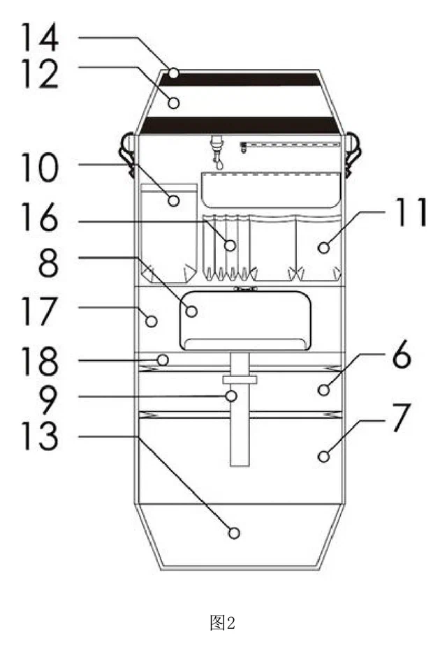
Fold-Out Desk Organizer Insert for School Backpacks
Backpack insert that unfolds into a hanging desk organizer for workbooks, stationery and a water bottle.
Patent CN209436546U
School, Office & Art
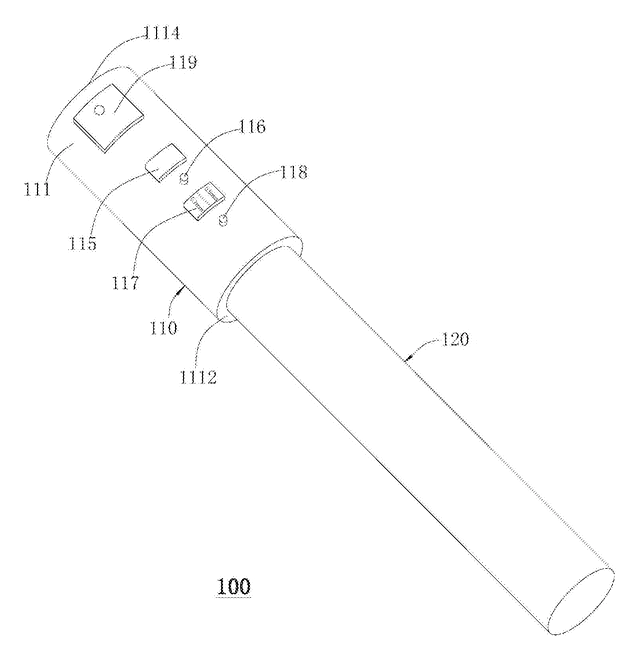
Smart Pencil Cap That Checks the Point with a Camera
Electronic pencil cap that photographs the point, measures it and reminds you to sharpen.
Patent CN106427302B
School, Office & Art
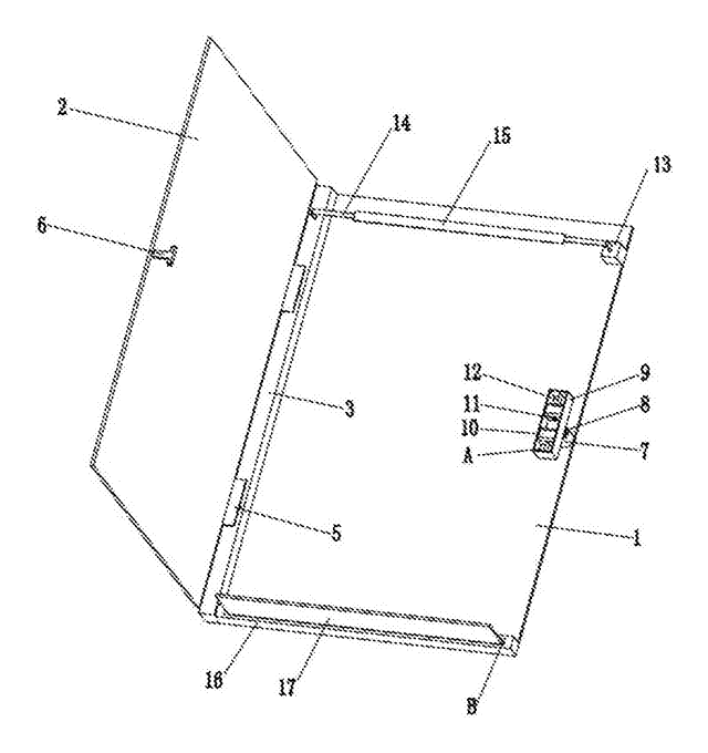
Expanding Clipboard Folder with Spring-Mounted Hinge and Catch
Hard folder whose spring-mounted hinge and catch let the cover clamp any thickness of paper.
Patent CN105667120B
School, Office & Art
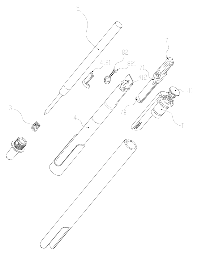
Slide-Action Retractable Pen with a Friction-Loaded Cam That Ignores Gravity
Slide-action retractable pen whose spring-pressed cam latch stays put whichever way the pen is held.
Patent CN217671900U
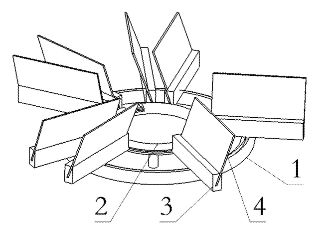
School, Office & Art
Carousel Business Card Holder with Rolling Card Trays on Twin Ring Tracks
Desk card holder: angled card trays roll on wheels around two concentric ring tracks and lift out.
Patent CN105774300B
Browse by category
- Apparel & Accessories (41)
- Baby & Kids (26)
- Bags & Luggage (15)
- Bath & Personal Care (27)
- Car Accessories (22)
- Furniture, Bedding & Storage (21)
- Garden & Outdoor (29)
- Health & Wellness (12)
- Home, Kitchen & Cleaning (44)
- Lighting (21)
- Packaging & Containers (11)
- Pet Products (10)
- Phone & Camera Accessories (8)
- Retail Display (22)
- School, Office & Art (31)
- Sports & Recreation (40)
- Tools & Workshop (49)
- Toys & Games (20)
This page is based on the public patent document CN114987093B, assigned to Kunming University of Science and Technology. IP2M is an independent manufacturing service and is not affiliated with, endorsed by or licensed by the patent owner. Images marked as concept renderings are illustrations, not photos of an existing product. Patent status information is provided for reference only and is not legal advice; confirm freedom to operate for your market before production. Full disclaimer.