
Patent CN114999345B
Updated November 7, 2026LED Blister Light Box with Quick-Release Shade and Adjustable Stand
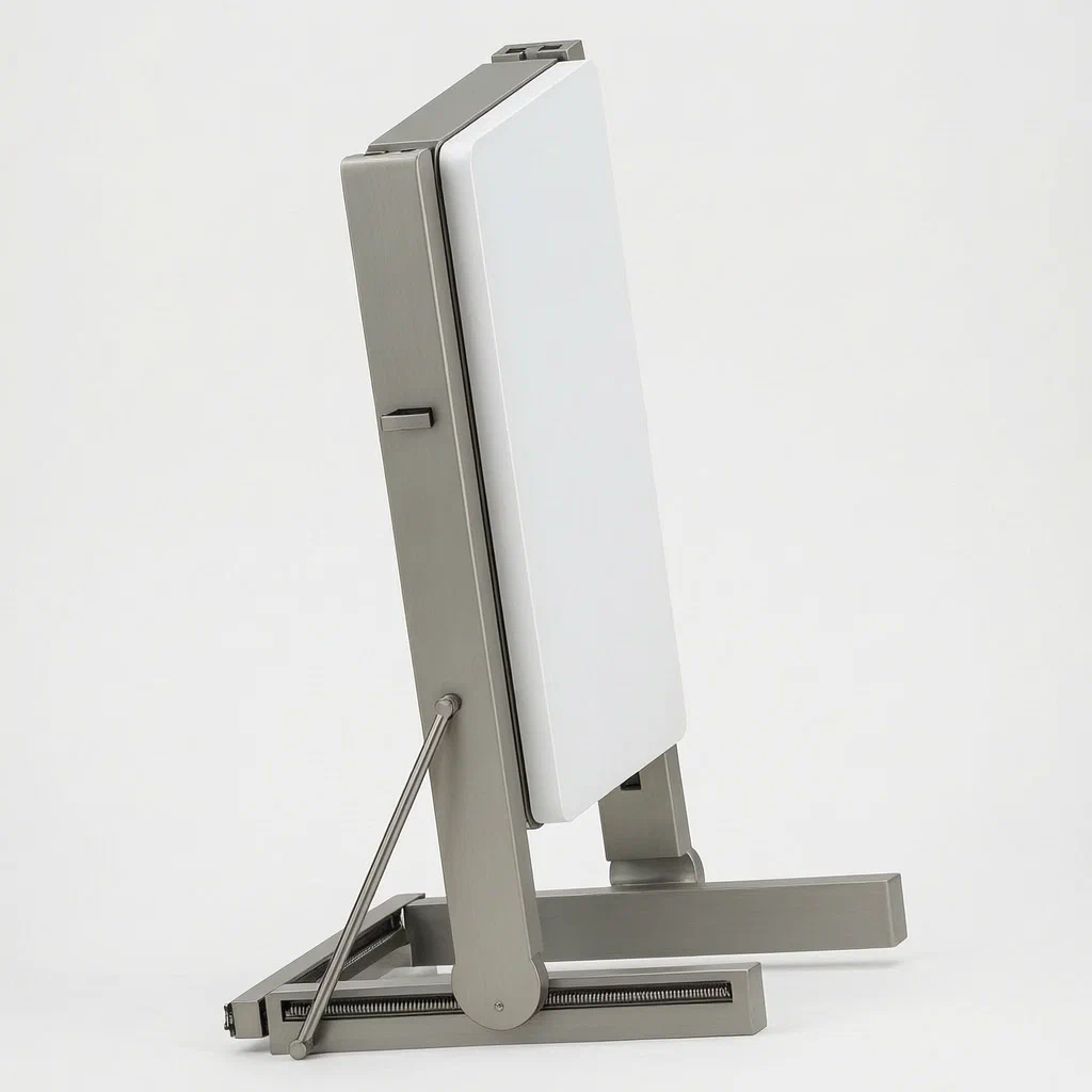
Standard light boxes often require unscrewing panels or prying off shades to change graphics, risking damage to the acrylic and slowing down store updates. This patent describes an LED blister light box where the shade attaches via clamping bars into sleeves, locked further by a cassette. To remove it, you slide the shade sideways to disengage the lock, then press a hidden plate which retracts the clamps, allowing the shade to lift off freely. The base unit mounts on a frame that slides vertically in a directional groove and tilts via two adjustment screws linked by a belt, offering flexible positioning for retail environments.
- China invention patent - active
- No filings outside China
- Retail signage hardware
- Spring-loaded release, belt-synced tilt
Splat! What let you down?
🔓
Tool-free release
A side-slide and press mechanism detaches the shade instantly for graphic swaps.
⚖️
Stabilized clamping
Wrapping sleeves and arc-shaped strips secure the shade against loosening during use.
📐
Synchronized tilt
Two adjustment screws connected by a belt ensure the box tilts evenly without binding.
↕️
Adjustable height
T-shaped sliding strips allow vertical positioning within a fixing frame with spring locks.
Bring this product to market
- ✓ Patent review Patent family and legal status reviewed in the relevant jurisdictions.
- 2 Product brief · now How it works, uses and options written up
- 3 Prototype First samples for buyers to review
- 4 Pilot run Small first batch for launch customers
- 5 Volume production Repeat orders at scale
Buyer interest
– of 100 buyers needed to start prototyping
One click, no sign-up. Each vote is one real visitor, and products with the most interest go to prototyping first.
Build team: no members yet. Need a partner, co-funding or skills to build this? Join and we introduce the team once it forms.
Patent Rights & Team Participation
Before joining a development team, participants should ensure they have the necessary rights or authorization to participate in the project.
Participation is generally appropriate where:
- You own the relevant patent rights or have obtained permission or a license from the rights holder.
- The relevant patent rights have expired or have been legally invalidated in the jurisdictions where the planned activities will take place.
- The planned development, manufacturing, and commercialization activities have been independently assessed and do not infringe applicable patent rights in the relevant jurisdictions.
Important: Being located outside a country where a patent is protected does not automatically exempt you from patent infringement risks. Patent rights may apply based on where development, manufacturing, use, sale, or import activities take place.
IP2M does not grant any patent license or authorization through team participation. Joining a project does not provide permission to use, manufacture, or commercialize patented technology.
The problem
Retailers frequently need to update signage, but traditional light boxes often have fixed frames or require tools to open. This slows down marketing changes and risks cracking the plastic shade if pried open incorrectly. Additionally, adjusting the viewing angle or height of a freestanding display usually involves loosening multiple bolts independently, leading to uneven tension or the unit falling out of alignment.
The solution
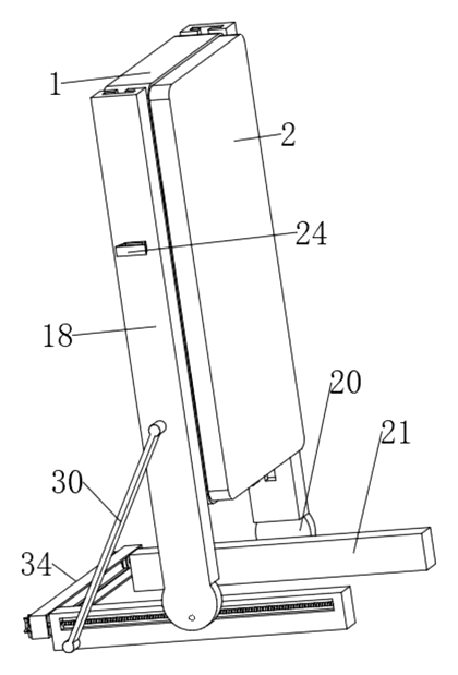
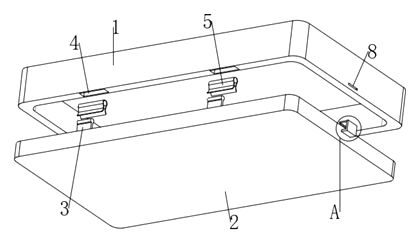
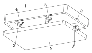
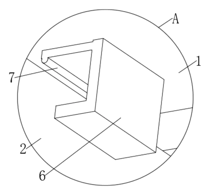
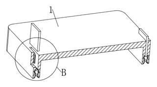
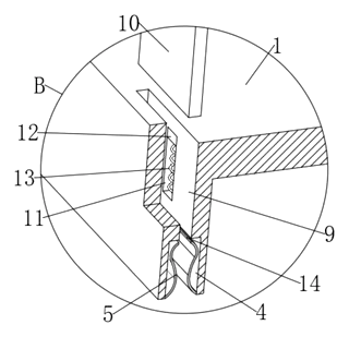
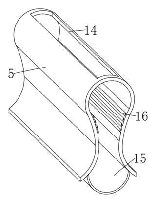
The patent describes a structure where the lamp shade (2) connects to the box body (1) via a mechanical interlock rather than screws. Symmetrical clamping bars (3) on the shade insert into cutting ferrules (5) mounted in grooves on the box front. A secondary cassette (6) with an L-shape tip and integral draw-in strip (7) engages a first slot (8) to lock the position. For removal, the user slides the shade laterally to disengage the cassette, then presses a clamp plate (10). This plate moves downward along a first spout (11), compressing a first spring (13), which pushes the clamping bars out of the ferrules.
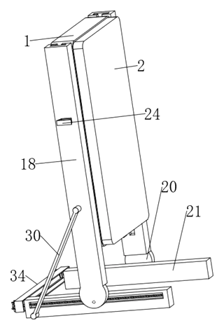
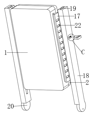
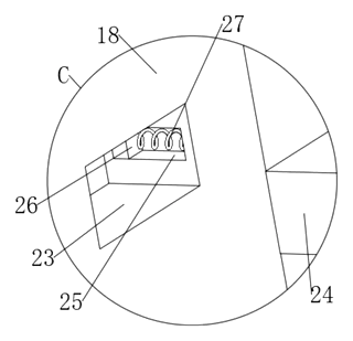
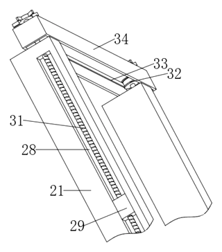
The mounting system uses sliding strips (17) with T-sections that fit into a directional groove (19) on a fixing frame (18). Height is adjusted by pulling out a butt joint block (24) and moving the box; releasing it allows a second spring (27) to snap it back into place. Angle adjustment is achieved through two adjusting screws (31) driven synchronously by a belt (33) connecting two belt wheels (32), ensuring smooth, even tilting.
Who it is for
- Retail chain managers who need fast, tool-free graphic updates for promotional signage across multiple stores.
- Trade show exhibitors requiring portable displays with adjustable angles and heights to fit varying booth layouts.
- Signage manufacturers looking for a patented mechanical solution that differentiates their product line from standard screw-fixed boxes.
- Interior designers specifying custom lighting fixtures where clean lines and hidden mechanisms are preferred over visible hardware.
How it works
The main parts
| No. | Part | What it does |
|---|---|---|
| 1 | Box Body | Main housing containing the LED source. |
| 2 | Lamp Shade | The translucent cover holding the graphic. |
| 3 | Clamping Bars | Insert into ferrules to hold the shade. |
| 5 | Cutting Ferrule | Sleeve-like holder with thin middle section. |
| 6 | Cassette | L-shaped lock engaging the first slot. |
| 10 | Clamp Plate | Pressed to retract clamping bars. |
| 11, 13 | Spout & Spring | Guide and return the clamp plate. |
| 17 | Sliding Strip | T-shaped rail for vertical movement. |
| 18 | Fixing Frame | Outer frame holding the sliding strips. |
| 24, 27 | Lock Block & Spring | Secures the height position. |
| 31, 32, 33 | Screw, Wheel, Belt | Synchronizes angle adjustment. |
Operating steps
- Installation: Align the clamping bars (3) with the mounting grooves (4) and push the lamp shade (2) onto the box body (1). Slide the shade slightly so the cassette (6) enters the first slot (8), locking it in place.
- Removal: Push the shade transversely (sideways) to move the cassette (6) out of the first slot (8). Press the clamp plate (10); this forces the first slider (12) down, compressing the first spring (13). The clamp plate (10) enters the cutting ferrule (5) via the opening and pushes the clamping bar (3) out, releasing the shade.
- Height Adjustment: Pull out the butt joint block (24) on the side. Move the box body up or down along the directional groove (19). Release the block; the second spring (27) snaps it into the next butt joint groove (22).
- Angle Adjustment: Rotate one adjusting screw (31). The belt (33) drives the second screw via the belt wheels (32), causing both adjusting blocks (29) to move simultaneously along the adjusting grooves (28), tilting the fixing frame (18) evenly.
Applications
Retail Store Signage
Ideal for high-turnover promotions where staff need to swap posters daily. The tool-free release prevents damage to the acrylic shade and speeds up labor efficiency compared to screw-based systems.
Trade Show Booths
Exhibitors can adjust the height and angle of the display to match eye-level sightlines or specific booth structures. The synchronized belt mechanism ensures the display doesn’t wobble when tilted.
Museum and Gallery Displays
Provides controlled lighting for artifacts or informational panels. The ability to quickly change interpretive text without tools allows curators to update information rapidly while maintaining a clean aesthetic with hidden hardware.
Corporate Lobby Information Boards
Used for internal announcements or visitor guidance. The adjustable tilt allows optimal viewing angles for standing crowds, and the secure clamping prevents accidental detachment in high-traffic areas.
Where it is less suitable
- Outdoor High-Wind Environments: The patent does not describe weather sealing or wind-load ratings; standard indoor usage is assumed.
- Fixed-Position Industrial Use: If the sign never needs updating or adjusting, simpler welded frames are more cost-effective.
- Heavy Metal Shades: The clamping mechanism is designed for lightweight blister/acrylic shades; heavy materials may stress the springs or slots.
Patent & Production
At a glance
| Patent number | CN114999345B (application CN202210604820) |
| Type | China invention patent - protects product structure and method |
| Original title | A kind of LED blister lamp box (一种LED吸塑灯箱) |
| Patent owner | Xiamen Luz Opto Electronic Technologies Co ltd |
| Inventors | Huang Shengqi |
| Filing date | 2022-05-31 |
| Grant date | 2023-12-22 |
| Status (China) | In force - valid until at most 2042-05-31, provided annual fees are paid |
| Patent family | Public record shows Chinese filings only - no US, European, Japanese, PCT or other filings listed |
| Cited by | 0 later documents |
| Source | Google Patents (search for CN114999345B) |
What the claims cover, in plain language
Claim 1 - An LED blister lamp box comprising a box body and a lamp shade detachably connected. The box front has symmetric mounting grooves containing cutting ferrules (one end sealed, one open, thin middle). The shade has clamping bars with circular rear ends that insert into these ferrules. A cassette with an L-shaped tip and integral draw-in strip locks into a first slot. A release mechanism includes a clamp plate guided by a first spout and biased by a first spring; pressing the plate pushes the clamping bars out. Wrapping sleeves with stabilizing parts surround the clamping bars to prevent loosening.
Claim 2 - The box sides have T-shaped sliding strips that fit into a directional groove on an outer fixing frame, allowing vertical movement.
Claim 3 - The height lock consists of a butt joint block on the frame engaging grooves on the sliding strip, returned by a second spring.
Claim 4 - The angle adjustment uses two bottom plates with adjusting grooves containing adjusting blocks connected to the frame. Two adjusting screws thread into these blocks.
Claim 5 - The two adjusting screws are synchronized by belt wheels and a common belt, ensuring simultaneous rotation.
Claim 6 - A trough plate covers the belt and pulleys between the bottom plates for protection and stability.
This is a simplified reading for orientation only. The legal scope is defined by the exact claim wording in the official Chinese document.
What this means for US production
This patent was filed in China and is currently in force. The public record shows no US or other foreign counterpart. Making or selling this specific configuration in China requires the owner’s permission. However, because there is no US patent, the design itself does not restrict US importers or manufacturers under US patent law, provided no other US patents apply.
Two practical issues to review first:
- Other patents may exist. The field of modular retail displays and light box mechanics is crowded. While this specific combination of belt-synchronized tilt and spring-release shade appears unique to this filing, a freedom-to-operate (FTO) search should look for broader US claims on quick-release clamps and adjustable display stands.
- Component sourcing. The specialized cutting ferrules and belt-synced screw assemblies are custom parts. Ensure your supply chain can produce these tolerances consistently.
Customization and manufacturing
What can be customized
| Area | Options |
|---|---|
| Dimensions | Width, height, and depth of the box body and shade |
| Material | Acrylic or PC for the shade; aluminum or steel for the frame |
| Light Source | Edge-lit LEDs vs. back-panel arrays; color temperature |
| Finish | Powder coating colors for the frame; clear/frosted shade |
| Graphics | Double-sided printing options; magnetic inserts |
| Mounting | Floor stand, wall mount, or counter-top base variants |
Things to plan for (US market)
- UL 48 / UL 8750 - Standard for luminaires and LED equipment; required for electrical safety certification.
- FCC Part 15 - If the driver or any electronic components emit radio frequencies, compliance testing is needed.
- California Prop 65 - Screening for lead, cadmium, or phthalates in plastics and coatings.
- OSHA Stability Guidelines - For freestanding units, ensure the center of gravity meets general workplace safety recommendations to prevent tipping.
How a project runs
- Inquiry - Define dimensions, electrical specs, and quantity.
- Design - CAD modeling of the ferrule and belt-sync mechanism; select materials.
- Prototype - CNC samples for the frame; thermoformed shades; assemble and test release/tilt actions.
- Pilot Run - Injection mold trial for ferrules; powder coat batch; full electrical assembly.
- Production - Mass extrusion, molding, assembly, and QC.
Quantities & timeline
The complex ferrule and clamp plate parts likely require injection molds. The frame uses aluminum extrusion or sheet metal fabrication. The belt-drive system adds assembly time. Send us your target dimensions, electrical requirements, finish preferences, estimated quantity and we will reply with options.
Production notes
Tooling and process
Injection molding is typically used for the cutting ferrules and clamp plates to ensure precise fits for the clamping bars. Aluminum extrusion or sheet metal fabrication forms the box body and fixing frame. Acrylic forming creates the lamp shade. Assembly relies on slot-fit connections and screws, with adhesive potentially used for permanent seals if required.
Cost drivers
Sheet thickness affects the rigidity of the box and frame. Surface finish quality (powder coating) impacts visual appeal and cost. Packaging volume is significant due to the bulky nature of the assembled unit. The number of parts, particularly the small spring and belt components, increases assembly complexity. Print costs vary based on graphic integration. Actual costs typically depend on final materials, order volume, and supplier quotes.
Prototyping path
Start with a 3D model and load check to verify the tilt mechanism. Create cut and bent sample frames for initial fitment. Perform a flat-pack trial to assess shipping volume. Conduct load tests on the clamping bars to ensure they hold the shade securely. Finally, prepare tooling for injection-molded parts after design validation. The exact sequence depends on the final design and supplier feedback.
What we would change before tooling
We might simplify the wrapping sleeve geometry to reduce molding cycles. Adjusting the spring rate consistency is critical; we would prototype multiple spring strengths. We could integrate the trough plate into the bottom mold to save assembly steps. Verifying the belt tension tolerance is essential before locking in the wheel diameters.
Common failure points
Insufficient load capacity could let the clamping bars slip. Tipping is a risk if the base is too narrow for the extended height. Coating scratches may occur during assembly. Acrylic may crack near the clamping points if stress concentrates. Spring fatigue or inconsistent rates can cause premature release or stuck shades. Thread engagement issues may arise if the adjusting screws bind.
Patent drawings
Drawings reproduced from the public patent document for reference.
Frequently asked questions
How do I change the poster without tools?
Slide the lamp shade sideways to unlock the cassette. Then, press the small clamp plate located near the edge. This action pushes the internal clamping bars out of their sleeves, allowing you to lift the shade straight off.
Can I adjust the height of the display?
Yes. The box body slides vertically within the fixing frame using T-shaped rails. You pull out a locking block on the side, move the box to the desired position, and release the block, which snaps back into place with a spring.
Is the tilt angle adjustable?
Yes. Two screws at the base control the tilt. They are connected by a belt, so turning one adjusts both simultaneously, keeping the display level and preventing binding.
What material is the shade made of?
The patent refers to a “blister” lamp shade, which typically implies thermoformed acrylic or polycarbonate. These materials offer good light diffusion and impact resistance. Specific grades are confirmed in design.
How durable is the release mechanism?
The mechanism uses springs and sliding parts. Durability depends on the spring rating and material choice, which are set in design and verified through cycle testing on prototypes.
Does it come with a power cord?
The patent describes the structural housing. Electrical components like drivers and cords are added during manufacturing. Specifications depend on the voltage and plug type required for your region.
Can this design be made and sold in the US?
The patent is in force in China, but the public record shows no US counterpart. Therefore, this specific design does not restrict manufacturing or sales in the US under US patent law. However, we recommend a freedom-to-operate check to ensure no other US patents cover similar quick-release mechanisms.
Are you affiliated with the patent owner?
No. IP2M is an independent design and manufacturing service working from the public patent document.
Request a quote
Click Request a Quote below to see our email address - copy it, or open your email app with a ready-made message. Please mention patent CN114999345B in the subject.
Helpful details to include:
- Your company and channel (retail brand, signage supplier, trade show agency)
- Dimensions (width x height x depth) and shade material preference
- Electrical specs (voltage, plug type, LED color temp)
- Finish for the metal frame (color, texture)
- Estimated quantity and target price
- Timeline - when you would like samples and the first shipment
You can also reach us at (332) 203-9997.
Page editor: Emily Zhang, Product Editor · IP2M
Last updated November 7, 2026. If something on this page looks wrong, email [email protected] and we will check it against the patent.
Interested in building this?
Tell us your target market, quantity and timeline. We reply with options for prototyping, small-batch runs or volume production.
Send your inquiry to
Please put CN114999345B in the subject line and tell us your company, country, estimated quantity and timeline.
Prefer to talk? Call (332) 203-9997.
More product-ready patents
All Retail Display patents →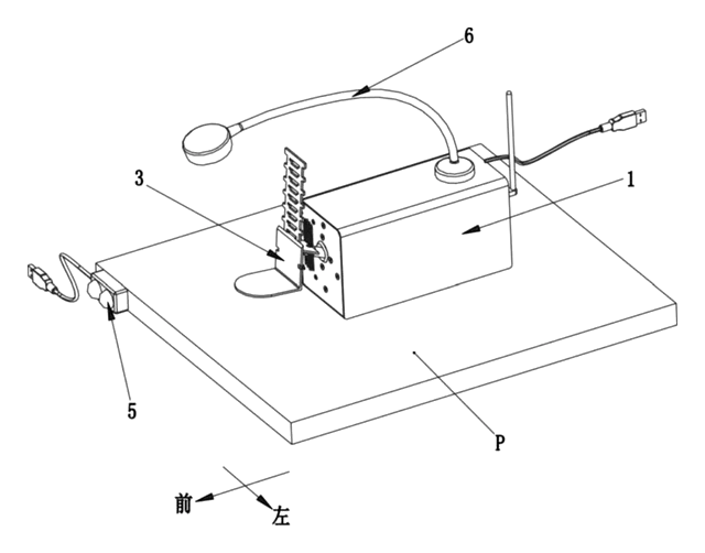
Retail Display
Motorized Shelf Display That Presents a Product to Shoppers
Shelf unit that lifts a product over the price rail toward shoppers when a sensor detects them.
Patent CN215077184U
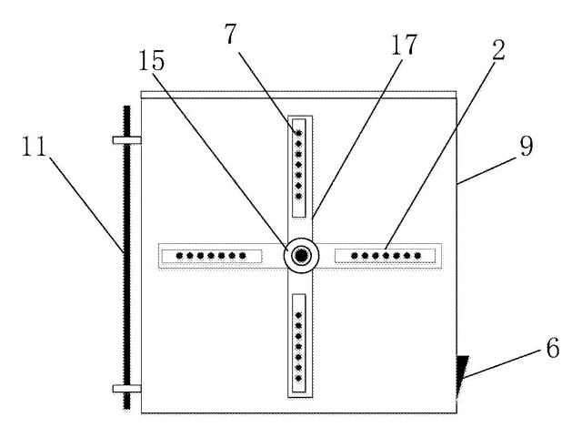
Retail Display
Portable Advertising Light Box with Spinning LED Display
Portable ad box whose spinning LED bars draw images and text; content changes by wireless or USB.
Patent CN207425291U
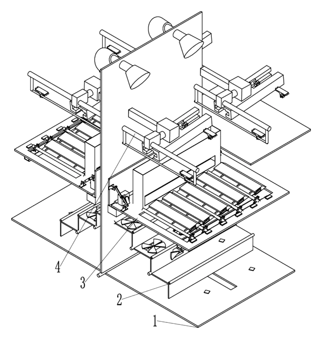
Retail Display
Automated Folding Store Shelf That Pushes Products Up to the Customer
Double-sided shelf for unmanned stores: folding tiers, screw pushers and lift cylinders present stock.
Patent CN109645754B
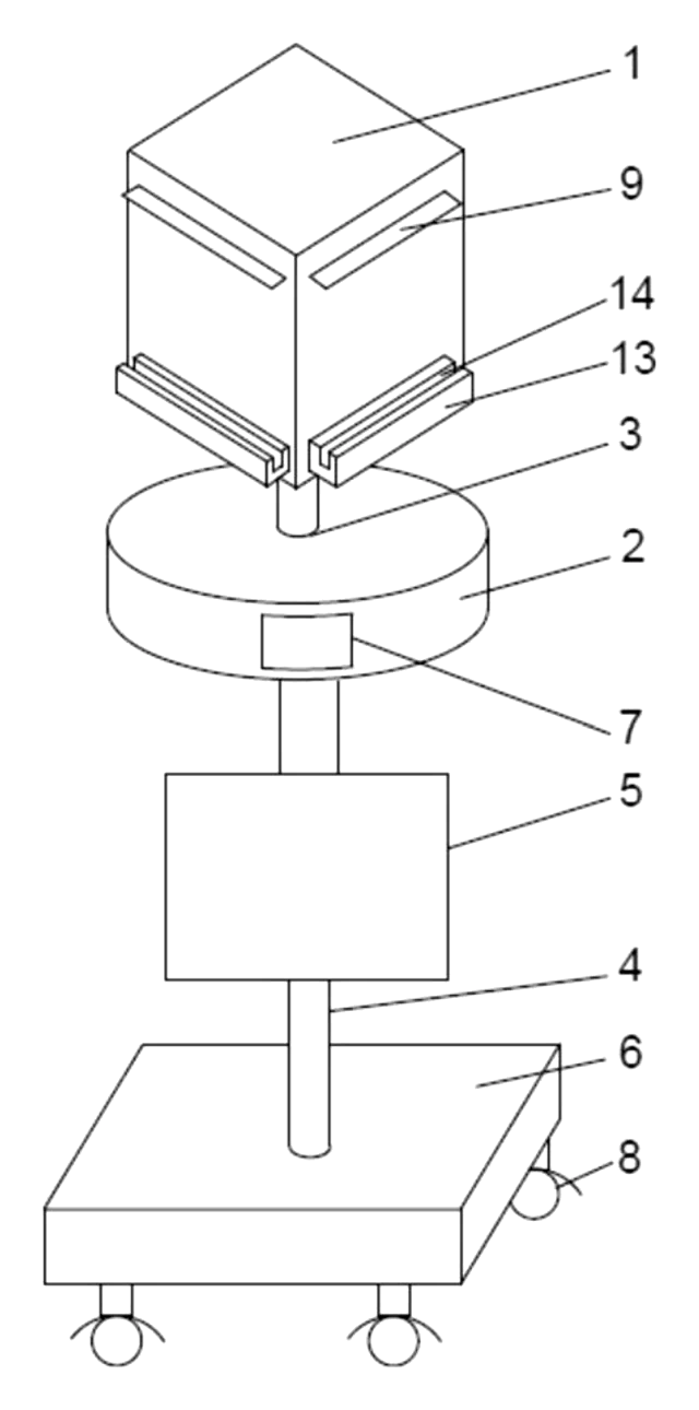
Retail Display
Motorized Rotating Display Pedestal with Lift Column, Info Screen and Clip-On Display Racks
Mobile pedestal: motorized rotating cube with lit faces and racks, electric lift column and info screen.
Patent CN208875862U
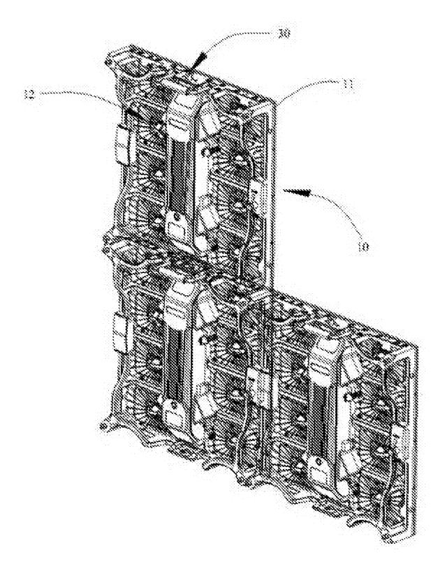
Retail Display
Thin Outdoor LED Video Wall Cabinet with Magnetic Modules and Tool-Free Locks
Thin outdoor LED wall cabinet: magnetic modules and rear body, rotary locks, finned rear cooling.
Patent CN205354557U
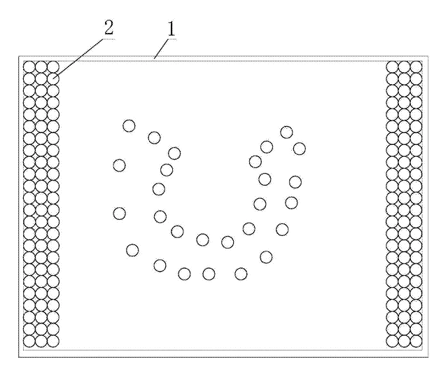
Store & Display
Magnetically Repositionable LED Advertising Panel
LED panel whose lamp beads slide to new positions via an external electromagnet.
Patent CN205487209U
Browse by category
- Apparel & Accessories (46)
- Baby & Kids (28)
- Bags & Luggage (17)
- Bath & Personal Care (30)
- Car Accessories (25)
- Furniture, Bedding & Storage (23)
- Garden & Outdoor (32)
- Health & Wellness (14)
- Home, Kitchen & Cleaning (48)
- Lighting (23)
- Packaging & Containers (12)
- Pet Products (11)
- Phone & Camera Accessories (9)
- Retail Display (25)
- School, Office & Art (35)
- Sports & Recreation (45)
- Tools & Workshop (54)
- Toys & Games (22)
This page is based on the public patent document CN114999345B, assigned to Xiamen Luz Opto Electronic Technologies Co ltd. IP2M is an independent manufacturing service and is not affiliated with, endorsed by or licensed by the patent owner. Images marked as concept renderings are illustrations, not photos of an existing product. Patent status information is provided for reference only and is not legal advice; confirm freedom to operate for your market before production. Full disclaimer.