
Patent CN115299808B
Updated November 8, 2026Vacuum Cleaner Roller Brush with Integrated Crushing Mechanism for Deep Cleaning
Standard vacuum brushes often struggle with large debris or get tangled by long fibers, requiring frequent manual cleaning of the roller. This design integrates a crushing roller directly behind the main brush, driven by the same motor. As the brush sweeps dirt forward, the crusher breaks up clumps, preventing clogs and improving suction efficiency. The modular frame allows for quick disassembly via spring-loaded pins, making maintenance easier without tools. A sliding blade assembly further assists in cutting through hair tangles, ensuring consistent performance during deep cleaning tasks.
- China invention patent - in force
- No filings outside China
- Vacuum cleaner components
- Integrated crushing roller and cutter
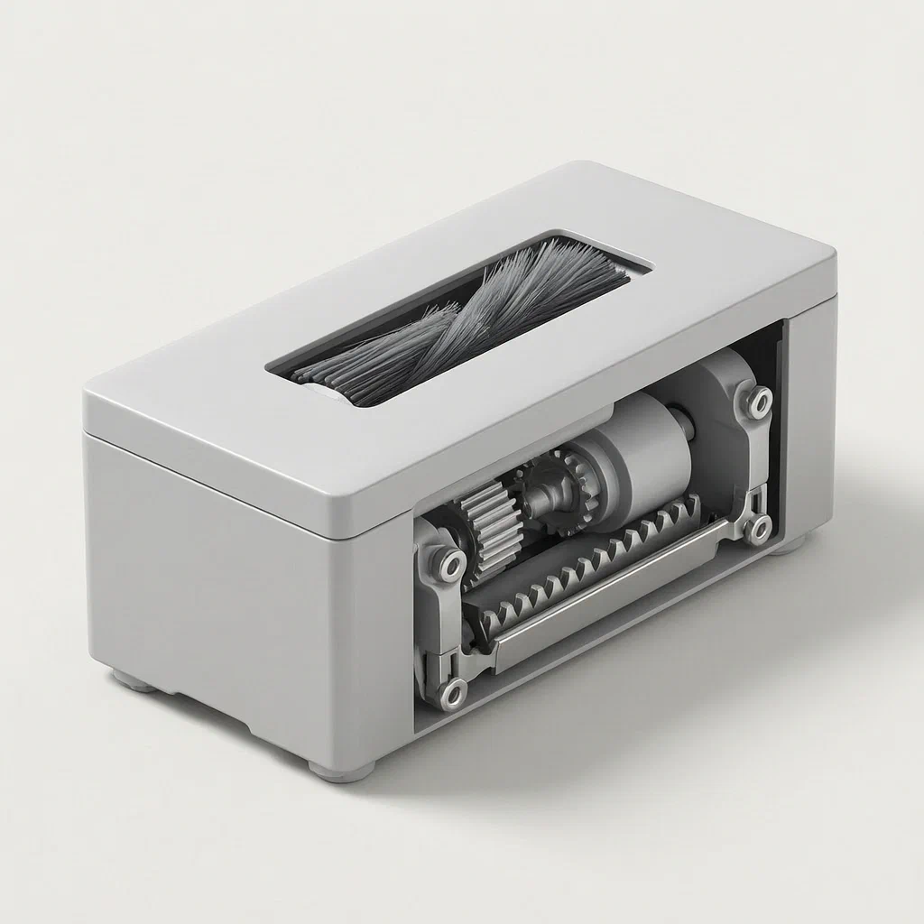
Splat! What let you down?
🔄
Dual Action
The main brush sweeps while a rear crushing roller breaks down debris, all driven by one motor.
⚙️
One-to-Four Drive
A central gear system distributes power to two brushes and two crushers for balanced operation.
🔧
Quick Release
Spring-loaded push plates and positioning pins allow tool-free removal of the roller assembly.
✂️
Anti-Tangle Cutter
A sliding blade assembly cuts hair and fibers before they wrap around the brush shaft.
Bring this product to market
- ✓ Patent review Patent family and legal status reviewed in the relevant jurisdictions.
- 2 Product brief · now How it works, uses and options written up
- 3 Prototype First samples for buyers to review
- 4 Pilot run Small first batch for launch customers
- 5 Volume production Repeat orders at scale
Buyer interest
– of 100 buyers needed to start prototyping
One click, no sign-up. Each vote is one real visitor, and products with the most interest go to prototyping first.
Build team: no members yet. Need a partner, co-funding or skills to build this? Join and we introduce the team once it forms.
Patent Rights & Team Participation
Before joining a development team, participants should ensure they have the necessary rights or authorization to participate in the project.
Participation is generally appropriate where:
- You own the relevant patent rights or have obtained permission or a license from the rights holder.
- The relevant patent rights have expired or have been legally invalidated in the jurisdictions where the planned activities will take place.
- The planned development, manufacturing, and commercialization activities have been independently assessed and do not infringe applicable patent rights in the relevant jurisdictions.
Important: Being located outside a country where a patent is protected does not automatically exempt you from patent infringement risks. Patent rights may apply based on where development, manufacturing, use, sale, or import activities take place.
IP2M does not grant any patent license or authorization through team participation. Joining a project does not provide permission to use, manufacture, or commercialize patented technology.
The problem
Traditional vacuum cleaner roller brushes rely solely on rotation to agitate carpets and sweep debris. When faced with larger particles, clumps of dust, or long hair, these brushes often fail to break down the material effectively. Instead, the debris can cause clogging in the intake port or wrap tightly around the brush shaft, reducing agitation and stopping the brush from spinning. This requires users to frequently stop cleaning and manually cut away tangled hair or remove blockages. Furthermore, many existing designs make it difficult to access the brush for maintenance, as the rollers are often fixed within complex housing structures that require tools to open.
The solution
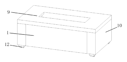
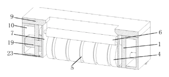
- Mounting Frame (1): The central chassis holds all moving parts. It features guide ways (2) on the inner top surface for sliding components and rotatable connections for the drive assemblies.
- Coupling Assembly (3): Located at both ends of the frame, this assembly connects the rotating rollers to the drive shafts. It uses a connecting sleeve (16) with an internal spring (17) and push plate (18).
- Roller Brush (4): The primary cleaning element, inserted into the coupling assembly. Its outer surface has multiple recesses (5) to accommodate the crushing and cutting mechanisms.
- Crushing Roller (6): Positioned above and behind the main brush inside the frame. It rotates to break down debris swept by the main brush.
- Cutting Assembly (8): Slides into the guide ways (2). It consists of a connecting strip (13) holding multiple blades (14) and a cleaning block (15). The block’s wedge shape aligns with the recesses in the main brush to cut tangled fibers.
- Drive Mechanism: A single motor (19) drives a central driving gear (20). This gear meshes with two sets of driven gears (21, 22), which rotate both the roller brushes and the crushing rollers simultaneously.
- Protective Housing (10): Encloses the motor and gears on the sides of the frame, keeping dust out and noise down.
Who it is for
- Vacuum cleaner brands looking to differentiate their upright models with advanced debris handling capabilities.
- Commercial cleaning equipment manufacturers needing robust heads that handle heavy soil loads without frequent clogging.
- Aftermarket component suppliers seeking replacement heads with superior anti-tangle features compared to standard OEM parts.
- Robot vacuum developers integrating high-performance floor modules into autonomous navigation systems.
How it works
The main parts
| No. | Part | What it does |
|---|---|---|
| 1 | Mounting Frame | Structural base holding the guides and bearings. |
| 2 | Guide Ways | Tracks for the sliding cutting assembly. |
| 3 | Coupling Assembly | Connects rollers to the drive; allows quick release. |
| 4 | Roller Brush | Main sweeping element with surface recesses. |
| 6 | Crushing Roller | Breaks down debris after it passes the main brush. |
| 8 | Cutting Assembly | Blades and blocks that slide in to cut tangles. |
| 19 | Motor | Single power source for the entire system. |
| 20-22 | Gears | Distribute torque from the motor to the four rotating elements. |
Operating steps
- Activation: The motor (19) starts, turning the driving gear (20).
- Power Distribution: The driving gear rotates two driven gears (21) connected to the roller brushes and two driven gears (22) connected to the crushing rollers. This creates a synchronized “one-to-four” motion.
- Sweeping and Crushing: The roller brush (4) agitates the floor surface, pushing debris forward. The crushing roller (6) immediately processes this debris, breaking up clumps before they enter the suction path.
- Tangle Prevention: If hair wraps around the brush, the user can slide the cutting assembly (8) along the guide ways (2). The blades (14) and cleaning block (15) interact with the brush’s recesses (5) to sever the wrapped fibers.
- Maintenance: To replace the brush, the user pushes the push plate (18) in the coupling assembly (3). This compresses the spring (17), releasing the tension on the positioning pin, allowing the roller brush (4) to be pulled out without tools.
Applications
Pet-heavy households
Long hair and fur are common issues that jam standard vacuums. The integrated cutting assembly allows users to quickly slice through tangles without removing the brush, while the crushing roller handles pet food crumbs and litter clumps efficiently.
Hardwood and tile floors
Fine dust and sand can accumulate in grout lines. The dual-action brush provides vigorous agitation to lift dirt, while the crushing mechanism prevents larger grit from causing scratches or clogging the nozzle.
Commercial office spaces
High-traffic areas generate significant paper waste and packaging debris. The robust crushing roller ensures that small boxes or crumpled paper do not block the airflow, maintaining suction power throughout the cleaning cycle.
Construction site cleanup
For light construction debris like drywall dust mixed with wood shavings, the powerful crushing action breaks down uneven materials, allowing the vacuum to handle a wider variety of waste types than a standard brush.
Where it is less suitable
- Delicate upholstery: The aggressive crushing action may damage soft fabrics or loose weaves if used without adjustment.
- Small handheld units: The complexity of the dual-drive gear system and protective housing makes this design too bulky for compact handheld vacuums.
- Wet environments: The patent does not specify waterproofing for the motor or gears, so this assembly should not be used on wet surfaces or liquids.
Patent & Production
At a glance
| Patent number | CN115299808B (application CN202210914730) |
| Type | China invention patent (发明专利) - protects product structure and method |
| Original title | A vacuum cleaner roller brush suitable for deep garbage clearance (一种适用于深层垃圾清理的吸尘器滚刷) |
| Patent owner | Futek Suzhou Precision Manufacturing Co ltd |
| Inventors | Wang Fan |
| Filing date | 2022-08-01 |
| Grant date | 2024-04-16 |
| Status (China) | In force - valid until at most 2042-08-01, provided annual fees are paid |
| Patent family | Public record shows Chinese filings only - no US, European, Japanese, PCT or other filings listed |
| Cited by | 0 later documents |
| Source | Google Patents (search for CN115299808B) |
What the claims cover, in plain language
Claim 1 defines a vacuum cleaner roller brush assembly comprising a mounting frame, a coupling assembly at each end, a roller brush inserted into the couplings, a crushing roller positioned above the brush, and a cutting assembly slidably mounted in guide ways. The frame includes a drive mechanism with a motor and gears that rotate both the brush and the crusher. The coupling assembly uses a spring and push plate for quick attachment/detachment. The cutting assembly includes blades and a cleaning block that aligns with recesses on the brush surface.
Claim 2 specifies that the top cover includes two symmetrically arranged partition plates and a flow guide port where the crushing roller is located.
Claim 3 adds a scraping plate at the bottom of the installation frame and rollers at the bottom of the protective shell to aid movement or sealing.
Claim 4 introduces a rubber parting strip fixed between the mounting frame and partition plate to prevent dust leakage into gaps.
This is a simplified reading for orientation only. The legal scope is defined by the exact claim wording in the official Chinese document.
What this means for US production
This patent was filed in China and is currently in force. Making or selling this specific design in China would require permission from the patent owner. However, the public record shows no US counterpart or foreign family members. Therefore, this patent does not restrict the manufacture or sale of this design in the United States.
Two issues are worth settling first:
- Other patents may exist. Vacuum cleaner technology is a crowded field with extensive prior art from major global manufacturers. We recommend a freedom-to-operate (FTO) review before launch, to check whether the gear ratio, quick-release coupling or crushing roller arrangement reads on existing US patents held by competitors like Dyson, Shark or iRobot.
- Component sourcing. The precision required for the gear meshing and the spring-loaded coupling suggests tight tolerances. Sourcing reliable motors and molded plastic parts that meet these specifications will be critical for performance consistency.
Customization and manufacturing
What can be customized
| Area | Options |
|---|---|
| Brush Material | Nylon, polypropylene, or rubber bristles depending on floor type |
| Gear Ratio | Adjusted to balance torque between the brush and crusher |
| Housing Color/Finish | Standard black, white, or custom brand colors |
| Blade Type | Stainless steel or hardened polymer for durability |
| Mounting Interface | Compatible with various vacuum body standards |
Things to plan for (US market)
- UL 60335-2-2 - Safety standard for household electric appliances, specifically vacuum cleaners. Electrical insulation and fire resistance of the motor housing must comply.
- RoHS / REACH - Restrictions on hazardous substances in plastics and electronics.
- CPSC Guidelines - General safety requirements for consumer products, particularly regarding sharp edges on the cutting assembly and pinch points in the gears.
- Energy Star - If applicable to the final appliance, the motor efficiency contributes to overall energy ratings.
How a project runs
- Inquiry - Define compatibility with target vacuum models and desired performance specs.
- Design - CAD modeling of the gear train, coupling assembly, and housing integration.
- Prototype - 3D printed housings and machined gears for fit and function testing.
- Pilot Run - Injection molding of final tooling, assembly, and endurance testing.
- Production - Mass manufacturing of molds, motors, and assembly lines.
Quantities & timeline
Tooling for the injection-molded housing and gears represents the primary upfront cost. Motor sourcing lead times depend on volume. Certification testing typically takes 4-6 weeks. Send us your target vacuum model, quantity, and certification needs and we will reply with options.
Production notes
Tooling and process
The housing and brush base likely require multi-cavity injection molds to manage costs. Gears need precision stamping or powder metallurgy for durability. The motor assembly involves automated winding and balancing.
Cost drivers
The high part count from the separate crushing roller, cutting assembly and complex gear train is likely a major cost driver. Mold complexity for the interlocking frames and spring-loaded couplings typically increases tooling expenses significantly.
Prototyping path
Start with SLA 3D printing for the housing to check fit. Machined gears are typically used to test meshing accuracy before committing to metal tooling. Functional samples will likely verify the one-to-four drive ratio.
What we would change before tooling
We might simplify the spring-loaded push plate mechanism if it proves prone to fatigue. Reducing the number of distinct plastic parts in the cutting assembly could lower mold counts and assembly time.
Common failure points
Thin walls in the housing may warp under heat from the motor. Gear teeth wear out if alignment is off. The spring in the coupling could lose tension over repeated use, leading to loose brushes.
Patent drawings
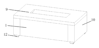
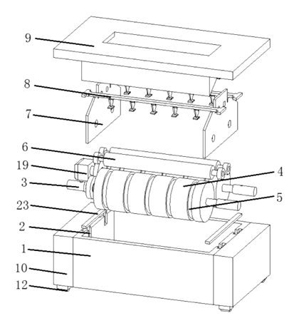
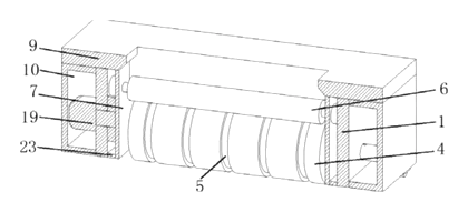
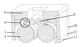
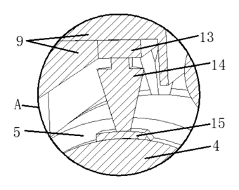
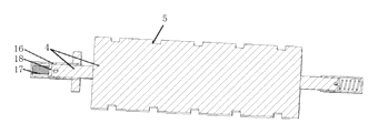
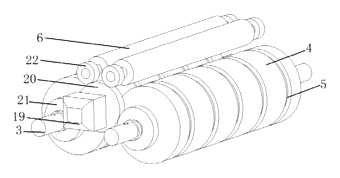
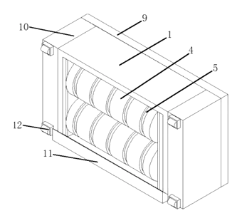
Drawings reproduced from the public patent document for reference.
Frequently asked questions
How does the crushing roller work?
It is driven by the same motor as the main brush but rotates independently. As the main brush sweeps debris forward, the crushing roller catches it and breaks down clumps or hard particles before they enter the suction tube, reducing clogs.
Is the brush easy to clean?
Yes. The coupling assembly uses a spring-loaded push plate. By pressing the plate, you release the positioning pin, allowing you to pull the roller brush out without any tools. This makes it easy to remove wrapped hair or replace the brush.
Can it handle long pet hair?
The design includes a sliding cutting assembly with blades. You can slide this assembly into place to cut through hair that has already wrapped around the brush, restoring functionality without disassembling the entire unit.
Does the extra weight affect maneuverability?
The addition of the crushing roller and second gear set increases the head’s weight slightly. However, the balanced one-to-four drive system distributes torque evenly, which helps maintain stability and traction on various floor types.
What materials are used?
The patent does not specify exact materials. Typically, such assemblies use durable plastics like ABS or PP for the housing, nylon for bristles, and metal alloys for gears and blades. Specific grades are confirmed during the design phase.
Is there a risk of damaging floors?
According to the patent, the crushing roller is designed for debris breakdown, not direct floor contact in the same way as the brush. Proper calibration of the height adjustment is crucial to ensure the crushing mechanism does not scratch delicate surfaces.
Can this design be made and sold in the US?
The patent is in force in China, but the public record shows no US counterpart. Therefore, this specific patent does not restrict manufacturing or selling in the US. However, a freedom-to-operate check is recommended to avoid infringing other existing US patents in the vacuum cleaner sector.
Are you affiliated with the patent owner?
No. IP2M is an independent design and manufacturing service working from the public patent document.
Request a quote
Click Request a Quote below to see our email address - copy it, or open your email app with a ready-made message. Please mention patent CN115299808B in the subject.
Helpful details to include:
- Your company and channel (vacuum brand, commercial equipment maker, aftermarket supplier)
- Target vacuum model or interface specifications
- Desired brush type (bristle material, hardness)
- Volume estimates and target price per unit
- Certification requirements (UL, CE, etc.)
- Timeline - when you would like prototypes and first production run
You can also reach us at (332) 203-9997.
Page editor: Emily Zhang, Product Editor · IP2M
Last updated November 8, 2026. If something on this page looks wrong, email [email protected] and we will check it against the patent.
Interested in building this?
Tell us your target market, quantity and timeline. We reply with options for prototyping, small-batch runs or volume production.
Send your inquiry to
Please put CN115299808B in the subject line and tell us your company, country, estimated quantity and timeline.
Prefer to talk? Call (332) 203-9997.
More product-ready patents
All Home, Kitchen & Cleaning patents →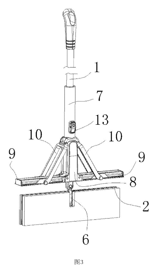
Home, Kitchen & Cleaning
Self-Wringing Flat Mop with Fold-Away Wringer
Flat mop with a built-in wringer that opens only when you wring and folds flat against the pole when you mop.
Patent CN207734114U
Home, Kitchen & Cleaning
Magnetic Double-Sided Window Cleaner with Dial-Set Magnet Strength
Magnetic window cleaner with a sealed, sliding magnet, dial-set strength for different glass thicknesses and a spring-held idle position.
Patent CN209360543U
Home, Kitchen & Cleaning
Metal Kettle with Magnetic Lid That Stays On When Pouring
Metal teapot/kettle with a magnet-held lid that does not fall off when pouring, and an insulated, vented lid knob.
Patent CN210540477U
Home, Kitchen & Cleaning
Reinforced Disposable Soup Spoon
Disposable soup spoon with a handle-to-bowl rib, stiffened edges and a ring foot to resist breaking.
Patent CN206964482U
Home, Kitchen & Cleaning
Self-Switching Double-Squeegee Window Cleaner
Cleaning head with two squeegee blades that switch automatically with the direction of movement.
Patent CN212630655U
Home, Kitchen & Cleaning
Self-Rinsing Roller Scrub Brush with Dirty-Water Tank
Powered roller brush that rinses and spins its bristles clean inside the body and stores the dirty water.
Patent CN210076909U
Browse by category
- Apparel & Accessories (50)
- Baby & Kids (29)
- Bags & Luggage (17)
- Bath & Personal Care (33)
- Car Accessories (26)
- Furniture, Bedding & Storage (25)
- Garden & Outdoor (34)
- Health & Wellness (14)
- Home, Kitchen & Cleaning (52)
- Lighting (24)
- Packaging & Containers (13)
- Pet Products (12)
- Phone & Camera Accessories (9)
- Retail Display (26)
- School, Office & Art (38)
- Sports & Recreation (48)
- Tools & Workshop (56)
- Toys & Games (23)
This page is based on the public patent document CN115299808B, assigned to Futek Suzhou Precision Manufacturing Co ltd. IP2M is an independent manufacturing service and is not affiliated with, endorsed by or licensed by the patent owner. Images marked as concept renderings are illustrations, not photos of an existing product. Patent status information is provided for reference only and is not legal advice; confirm freedom to operate for your market before production. Full disclaimer.