
Patent CN116160387B
Updated November 3, 2026Prestressed Anchor Pad Clamping Fixture with Dual Extrusion Units
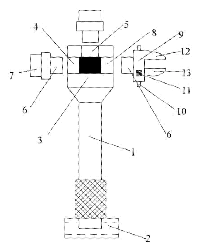
In construction quality control, prestressed anchor pads must be inspected for dimensional accuracy before installation. If the irregularly shaped metal body shifts during measurement, the data is invalid. This fixture solves that by gripping the anchor pad from both ends. A first unit stabilizes the narrow opening, while a second, more complex unit expands into the wide opening. Inside this second unit, angled arms push L-shaped plates against the inner and outer surfaces of the pad. Leaf springs lock these arms in position, creating a rigid frame that holds the pad perfectly still for precise detection.
- China invention patent - active
- No filings outside China
- Construction hardware inspection
- Steel platforms, leaf springs, rolling wheels
Splat! What let you down?
🔩
Dual-end stability
Grips both the narrow and wide mouths of the anchor pad to eliminate wobble.
📐
Angled arm expansion
Rotating inclined arms drive support plates outward to contact inner and outer walls.
🛡️
Spring-locked position
Leaf springs and limit blocks fix the arm angles, ensuring constant clamping pressure.
🎯
Precision ready
Designed specifically to prevent deviation during dimensional detection tasks.
Bring this product to market
- ✓ Patent vetted China-only family and legal status checked
- 2 Product brief · now How it works, uses and options written up
- 3 Prototype First samples for buyers to review
- 4 Pilot run Small first batch for launch customers
- 5 Volume production Repeat orders at scale
Buyer interest
– of 100 buyers needed to start prototyping
One click, no sign-up. Each vote is one real visitor, and products with the most interest go to prototyping first.
Build team: no members yet. Need a partner, co-funding or skills to build this? Join and we introduce the team once it forms.
The problem
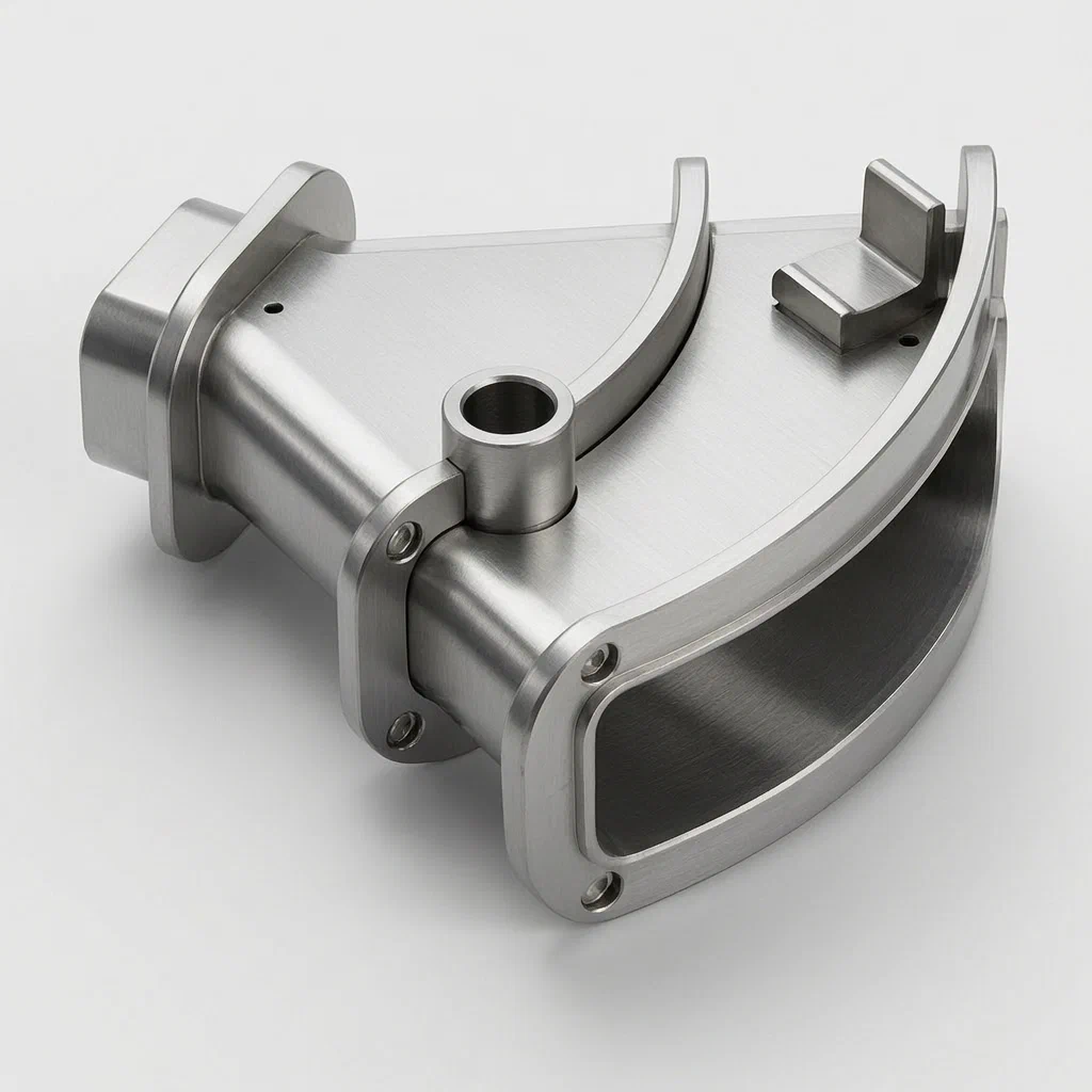
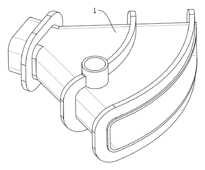
Prestressed anchor backing plates are critical components in construction, used to distribute tension forces in concrete structures. Before these parts are installed, they undergo rigorous quality detection to verify their geometry and integrity. However, the anchor pad body often has an irregular shape, tapering from a narrow mouth to a wide mouth. When placed on a standard flat surface or held by simple vices, the part can shift, tilt, or rotate slightly during the measurement process. This instability causes deviations in the reading, leading to inaccurate quality assessments and potential rejection of good parts or acceptance of faulty ones. Existing fixtures lack a mechanism to simultaneously stabilize both ends of this specific tapered geometry without interfering with the sensor paths.
The solution
The patented fixture addresses this by providing a dedicated clamping tool with two distinct extrusion units.
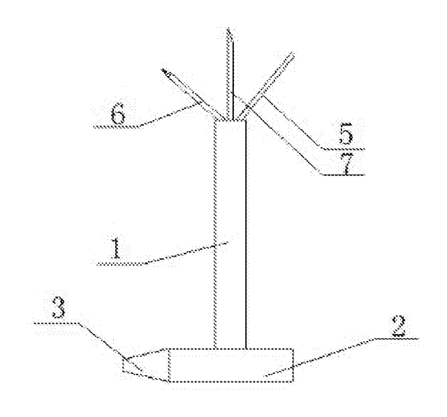
- First Extrusion Unit: Located at the narrow-mouth end of the anchor backing plate body, this unit provides a stable base point.
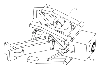
- Second Extrusion Unit: Located at the wide-mouth end, this is the core mechanical assembly. It consists of a horizontally movable platform that slides toward the workpiece.
- Inclined Arm Mechanism: On the front and rear side walls of the moving platform, first inclined arms are rotatably mounted. These arms connect to right-angle outer support plates.
- Contact Points: One face of the outer support plate contacts the end part of the anchor pad, while the perpendicular face inserts into the anchor pad body to contact its inner wall.
- Locking System: Second inclined arms connect the outer support plates to sliding blocks within grooves on the moving platform. Leaf springs apply elastic force to keep the arms pressed against limit blocks, fixing the geometry once deployed.
- Mobile Base: The entire second unit sits on a base table with rolling wheels that ride on conical anti-skid plates, allowing smooth transverse movement while maintaining alignment.
Who it is for
- Quality Control Labs in pre-stress technology firms that need repeatable fixtures for inspecting anchor pads.
- Construction Hardware Manufacturers producing custom anchor systems who require internal QC tools.
- Third-party Inspection Agencies serving the infrastructure sector, looking for specialized jigs for geometric verification.
- Tooling Engineers designing production lines where anchor pads must remain stationary during automated scanning.
How it works
The main parts
| No. | Part | What it does |
|---|---|---|
| 1 | Anchor Backing Plate Body | The workpiece being clamped (tapered shape). |
| 2 | First Extrusion Unit | Stabilizes the narrow-mouth end. |
| 3 | Second Extrusion Unit | Complex gripping assembly for the wide end. |
| 4 | Moving Platform | Slides transversely; carries the arms and sliders. |
| 5, 7 | Inclined Arms | Rotatable links that transmit motion to the plates. |
| 6 | Outer Support Plates | Right-angle plates that touch inner and outer walls. |
| 8 | Sliding Blocks | Move in grooves to adjust arm angles. |
| 9, 11 | Limit Plates/Blocks | Fixed stops that define the open/closed positions. |
| 10, 12, 19 | Leaf Springs | Provide elastic force to lock arms against limits. |
| 13 | Anti-skid Plate | Conical surface guiding the rolling wheels. |
| 15, 16 | Base Table & Wheels | Allows the unit to move smoothly across the fixture. |
Operating steps
- Placement: The anchor backing plate body is laid horizontally. Its narrow end rests against the First Extrusion Unit.
- Engagement: The operator pushes the Moving Platform (part of the Second Extrusion Unit) transversely toward the wide mouth of the plate.
- Deployment: As the platform moves, the geometry of the inclined arms rotates the Outer Support Plates. One face presses against the outer edge of the plate, while the other face inserts into the cavity to press against the inner wall.
- Locking: The sliding blocks reach their position in the grooves. The leaf springs pull the inclined arms tight against the Limit Plates and Stopper Blocks. This freezes the angle of the arms, locking the support plates firmly against the workpiece.
- Detection: With the part immobilized by dual-point contact and rigid arm linkage, sensors or calipers perform measurements without deviation.
Applications
Pre-stress anchor inspection
Used in factory settings to verify the diameter and concentricity of anchor pads before they are shipped to construction sites.
Concrete formwork quality checks
Helps inspectors check the mounting holes and sealing surfaces of the backing plates, which are critical for water-tightness in bridge decks.
R&D prototyping
Engineers developing new anchor geometries use this fixture to test how different shapes fit into standard inspection routines.
Automated assembly lines
Integrated into robotic cells where cameras scan the anchor pad; the fixture ensures the part doesn’t vibrate during image capture.
Where it is less suitable
- Non-standard geometries: Designed specifically for the tapered narrow-to-wide profile of standard anchor pads; may not clamp cylindrical or square blocks effectively.
- High-volume rapid sorting: The manual engagement of the moving platform may be slower than pneumatic chucks for very high-throughput lines.
- Heavy-duty machining: This is a light-to-medium duty clamping tool for inspection, not for holding parts under cutting forces.
Frequently asked questions
How does the fixture lock onto the anchor pad?
It uses a mechanical linkage. As you push the moving platform toward the pad, angled arms rotate. This action drives L-shaped plates so they press against both the inside and outside surfaces of the pad. Leaf springs then snap the arms against stoppers, locking them in place.
Why are there two extrusion units?
The anchor pad is tapered. The first unit supports the narrow end, acting as a pivot or stop. The second unit grips the wide end. This dual-point contact prevents the part from tilting or shifting during measurement.
Can it handle different sizes of anchor pads?
Yes. The sliding blocks move within grooves on the platform. By adjusting the starting position or modifying the groove length, the range of motion can accommodate various widths of the wide-mouth end.
What materials are used for the contact plates?
The patent describes metal components. In production, we typically use hardened tool steel for durability. Polymer pads can be added to the contact faces if you need to protect the finish of the anchor pads.
Is it difficult to operate?
No. It is a manual tool. You place the part, push the platform until the arms click into the locked position via the springs, and release when done. No power supply is needed.
Does it affect the accuracy of the inspection?
No. The design specifically aims to reduce deviation. By rigidly fixing the part’s position through the spring-locked arms, it ensures the anchor pad remains stationary while sensors or calipers measure it.
Can this design be made and sold in the US?
The patent is currently in force in China. Since there are no US patents covering this specific combination of inclined arms and spring-locking plates, you can generally manufacture and sell it in the US. However, always verify with a freedom-to-operate search to ensure no other US patents block similar clamping mechanisms.
Are you affiliated with the patent owner?
No. IP2M is an independent design and manufacturing service working from the public patent document.
Request a quote
Click Request a Quote below to see our email address - copy it, or open your email app with a ready-made message. Please mention patent CN116160387B in the subject.
Helpful details to include:
- Your company and industry (construction hardware, inspection lab, manufacturer)
- Dimensions of the anchor pads you need to clamp
- Volume of inspections per day (to determine durability needs)
- Integration requirements (manual bench vs. automated line)
- Estimated quantity and target price
- Timeline - when you would like samples and the first shipment
You can also reach us at (332) 203-9997.
Explore this product
Interested in building this?
Tell us your target market, quantity and timeline. We reply with options for prototyping, small-batch runs or volume production.
Send your inquiry to
Please put CN116160387B in the subject line and tell us your company, country, estimated quantity and timeline.
Prefer to talk? Call (332) 203-9997.
More product-ready patents
All Tools & Workshop patents →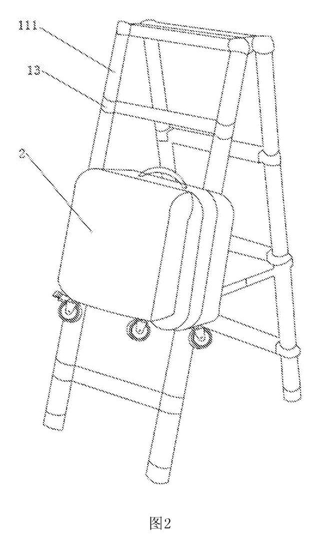
Tools & Workshop
Rolling Tool Box with Telescoping Step Ladder
Telescoping A-frame ladder with an attached rolling tool box that slides to your working height.
Patent CN206290197U
Tools & Workshop
Folding 3-Handle Wrench Multi-Tool
Folding three-handle wrench multi-tool with magnetic screwdriver bits, saw, file and bottle opener.
Patent CN205290875U
Tools & Workshop
Rolling Auto-Repair Tool Cabinet with Built-In Lights
Lockable rolling tool cabinet for car repair with interior lights, a lubricant tray, parts drawers and a tool bay.
Patent CN205989314U
Tools & Workshop
Wide-Opening Folding Bolt Cutter
Bolt cutter with linked, gear-meshing handles that open up to 190° and fold in half for storage.
Patent CN207206226U
Tools & Workshop
Nail-Holding Hammer with Fold-Out Drivers
Hammer with a nail-holding T-slot in the head and fold-out drivers stored in the handle.
Patent CN205254927U
Tools & Workshop
Modular Wrench with Screw-On Heads
Wrench handle with a three-way threaded hub for screw-on adjustable and hex heads, plus a pipe sleeve.
Patent CN206216564U
Browse by category
- Apparel & Accessories (31)
- Baby & Kids (23)
- Bags & Luggage (13)
- Bath & Personal Care (22)
- Car Accessories (19)
- Furniture, Bedding & Storage (17)
- Garden & Outdoor (25)
- Health & Wellness (10)
- Home, Kitchen & Cleaning (36)
- Lighting (17)
- Packaging & Containers (9)
- Pet Products (8)
- Phone & Camera Accessories (6)
- Retail Display (18)
- School, Office & Art (25)
- Sports & Recreation (32)
- Tools & Workshop (41)
- Toys & Games (17)
This page is based on the public patent document CN116160387B, assigned to Cangzhou Fuhua Prestress Technology Co ltd. IP2M is an independent manufacturing service and is not affiliated with, endorsed by or licensed by the patent owner. Images marked as concept renderings are illustrations, not photos of an existing product. Patent status information is provided for reference only and is not legal advice; confirm freedom to operate for your market before production. Full disclaimer.