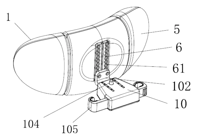
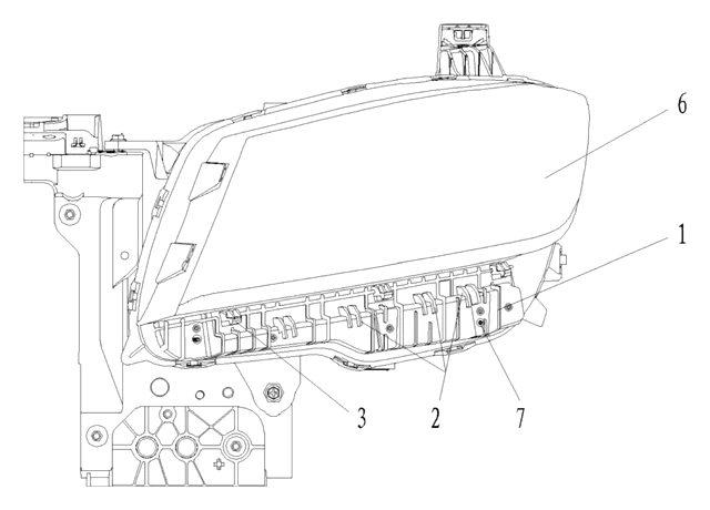
At a glance
| Patent number | CN116198404B (application CN202310296458) |
| Type | China invention patent (发明专利) - protects product shape, structure, and method |
| Original title | Seat Armrest with Telescopic Cup Stand and Automotive Seat (具有可伸缩杯托的座椅扶手及汽车座椅) |
| Patent owner | Dongshi Lear Automotive Seat Co., Ltd. Technical Center |
| Inventors | Yang Yang, Shi Yu, Xiao Ke |
| Filing date | 2023-03-22 |
| Grant date | 2025-04-04 |
| Status (China) | In force - valid until at most 2043-03-22, provided annual fees are paid |
| Patent family | Chinese filings only - no US, European, Japanese, PCT or other filings listed |
| Cited by | 0 later documents |
| Source | Google Patents (search for CN116198404B) |
What the claims cover, in plain language
Claim 1 defines a seat armrest comprising an armrest shell, an internal framework, a cup holder assembly, a driving piece, and a rotating component. The framework has guide chutes; the assembly has matching clamping blocks to slide along them. The driving piece connects the assembly to the framework to enable reciprocation. The rotating component allows the cup holder to switch between horizontal and vertical states. Specifically, the assembly includes a slide base box, a rotating shaft, and the cup holder. The rotating component uses a reset torsion spring, an end seat, a stirring seat/rod, a transmission seat, and a guide pin. The guide pin inserts into a slotted hole in the base box and interacts with a rotating chute on the framework. As the assembly slides, the chute guides the pin, causing the shaft to rotate the cup holder downward/upward.
Claim 2 adds a rotating shaft seat on the framework, guiding the shaft. Claim 3 specifies the driving piece is a spring coil. Claim 4 introduces a fixed rod, sliding auxiliary seat plate, and a damping gear. The auxiliary plate slides on a second chute, and the damping gear meshes with a rack on the framework to control speed. Claim 5 details a lock rod on the auxiliary plate engaging a locking member on the framework. Claim 6 describes the cup holder as two bars (first and second) pivoted together with torsion springs to provide clamping force. Claim 7 adds a cup holder support plate with a guide groove matching a guide bar on the shell. Claim 8 claims the automotive seat itself, incorporating the armrest described above.
This is a simplified reading for orientation only. The legal scope is defined by the exact claim wording in the official Chinese document.
What this means for US production
This patent was filed only in China and is currently in force there. Making, using, selling, or importing this specific design in China requires permission from the patent owner. Since there is no US counterpart, this specific patent does not restrict manufacturing or sales in the United States.
Two points to settle early:
- Other patents may exist. Automotive interior mechanisms are heavily patented globally. Major suppliers like Lear Corporation (related to the assignee here) and others hold extensive portfolios on cup holder deployment, locking mechanisms, and armrest structures. A freedom-to-operate (FTO) review is essential to check for active US patents covering similar telescoping or rotating armrest features before tooling.
- Complexity vs. Cost. The combination of sliding chutes, rotating pins, and damping gears increases part count and assembly steps. Simplifying the mechanism while retaining function may help meet US market price targets.
Customization and manufacturing
What can be customized
| Area | Options |
|---|---|
| Dimensions | Armrest width, length, and cup holder diameter to fit specific seat models |
| Materials | Plastic grade for shells/frameworks (e.g., PP, ABS); metal choice for springs/racks |
| Finish | Soft-touch coating, leather wrapping, or textured plastic for the visible shell |
| Mechanism | Damping level (gear ratio/spring stiffness); lock type (labyrinth vs. snap-fit) |
| Integration | Mounting brackets for left/right hand drive configurations |
Things to plan for (US market)
- FMVSS 201 - Occupant protection in interior impact; sharp edges or moving parts must not pose injury risk in a crash.
- SAE J1008 / SAE J1010 - Standards for cup holder strength and retention; tests pull-out force and vibration resistance.
- REACH / Prop 65 - Chemical restrictions on plastics and coatings used in interior components.
- ISO 16750 - Environmental testing for electrical/electronic components if sensors are added (not in this patent, but common in modern seats).
How a project runs
- Inquiry - Provide seat model specs, target dimensions, and quantity estimates.
- Design Review - Analyze FTO risks; adjust chute geometry and spring rates for desired feel.
- Prototype - CNC machine or 3D print key moving parts; assemble for kinematic testing.
- Pilot Run - Mold tools for plastic parts; stamp/machine metal frames; cycle test for durability.
- Production - Injection molding, metal fabrication, sub-assembly, final integration into seat frame.
Quantities & timeline
Tooling for the injection-molded plastic components (shell, base box, gears) is the primary lead time driver. Metal framework stamping dies require precise alignment for the guide chutes. Durability testing (cycle counts) typically dictates the validation phase duration. Send us your seat specifications, target cost, and projected volumes and we will reply with options.
Production notes
Tooling and process
Tooling is likely to center on the armrest shell, slide base box, cup holder and damping gear, with the internal framework and rack produced as formed metal parts. Springs, guide pins and the torsion spring are usually bought as standard or custom-wound components and checked on incoming inspection before final assembly. Because this is an interior trim part, the visible surfaces and the sliding interfaces deserve the tightest attention in the tooling plan.
Cost drivers
Part count is likely the main driver: the slide box, rotating shaft, guide pin, damping gear and lock rod each add tooling or assembly steps. Tooling tolerance for the guide chute and slotted hole also affects cost, because a loose fit can cause rattle or binding. Surface finish on the visible shell may add cost depending on the chosen wrap or coating.
Prototyping path
Typically, prototyping starts with 3D-printed shells and a machined or printed slide box to check the chute and pin motion. A functional sample with real springs and a damping gear is then used to tune return speed and clamping force. Cycle testing under load should follow before steel tooling is committed.
What we would change before tooling
We would likely simplify the lock rod and auxiliary plate if the same retention can be achieved with fewer parts. Wall thickness around the guide chute should be reviewed to avoid warping after molding. The damping gear ratio may need adjustment to suit different cup weights and vehicle vibration levels.
Common failure points
Rattle or binding in the guide chute is a likely risk if tolerances stack up poorly. Spring fatigue can weaken the self-return action over repeated cycles. The cup holder bars and torsion springs should be tested for clamping force after exposure to heat and spills, since interior temperatures vary widely.
Patent drawings
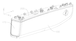
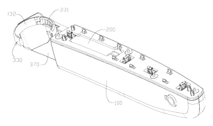
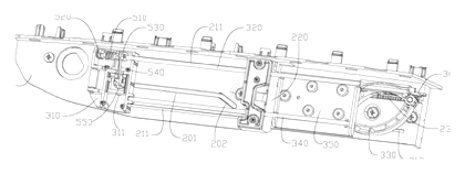
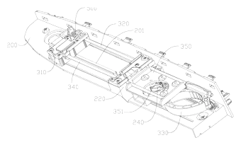
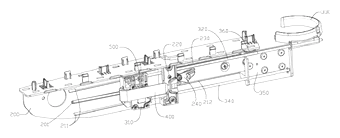
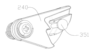
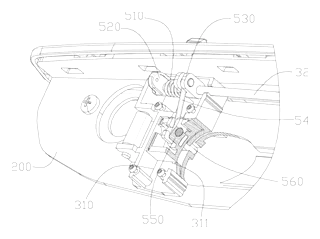
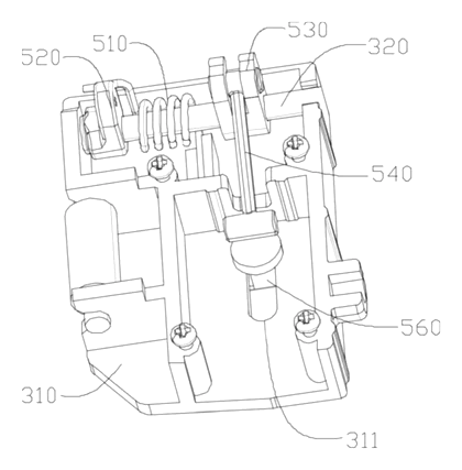
Drawings reproduced from the public patent document for reference.