
Patent CN116250750B
Updated November 3, 2026Quick-Release Lamp Tube Structure for Electric Towel Racks
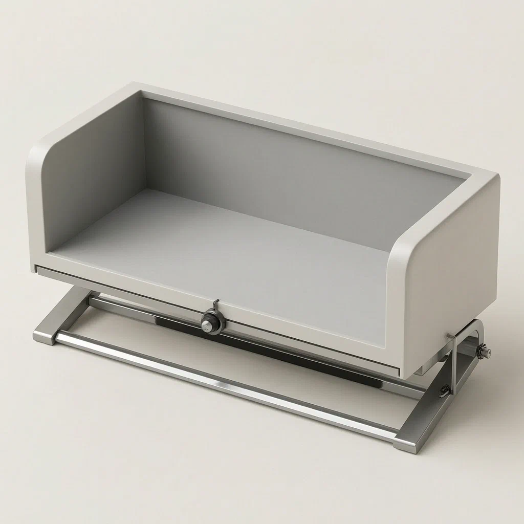
Replacing the internal UV or LED tube in an electric towel rack often requires waiting for the unit to cool down. Traditional designs force technicians to pinch the hot glass ends of the lamp tube and pull it out against the tension of the socket. This creates a safety hazard and slows down maintenance. The patented solution introduces a mechanical release system. By engaging a drive assembly, the lamp holder slides away from the tube, while a rotating support mechanism uses magnetic forces and squeeze plates to gently push the tube into a safe placement groove. This allows for tool-free, heat-resistant lamp replacement.
- China invention patent - In Force
- No filings outside China
- Electric towel rack accessories
- Magnetic and mechanical lamp release
Splat! What let you down?
🔄
Rotating Support
A central roller rotates to guide the lamp tube into a safe placement groove.
🧲
Magnetic Release
Electromagnets and permanent magnets work together to unlock the tube without manual force.
🛡️
Heat Safety
Allows lamp replacement while the rack is still warm, reducing burn risks.
🔧
Tool-Free Service
The sliding block and drive assembly enable quick disassembly without special tools.
Bring this product to market
- ✓ Patent vetted China-only family and legal status checked
- 2 Product brief · now How it works, uses and options written up
- 3 Prototype First samples for buyers to review
- 4 Pilot run Small first batch for launch customers
- 5 Volume production Repeat orders at scale
Buyer interest
– of 100 buyers needed to start prototyping
One click, no sign-up. Each vote is one real visitor, and products with the most interest go to prototyping first.
Build team: no members yet. Need a partner, co-funding or skills to build this? Join and we introduce the team once it forms.
The problem
Electric heating towel racks frequently use ultraviolet (UV) sterilization lamps or standard illumination tubes inside their housing. These components degrade over time due to usage cycles and thermal stress, requiring regular replacement. In conventional designs, the lamp tube is held firmly between two static holders. To remove it, a technician must physically grip the glass ends of the tube. However, because the rack generates significant heat during operation, the internal components remain hot long after the power is turned off. Gripping hot glass poses a risk of burns. Furthermore, forcing the tube out against spring-loaded contacts can cause misalignment or breakage of the delicate filaments if done improperly. Existing quick-release mechanisms often rely on complex latches that fail under high humidity or dust accumulation typical in bathroom environments.
The solution
The patented structure decouples the removal action from direct hand contact with the hot tube. It introduces a dynamic support system integrated into the towel rack’s chassis. When the service mode is activated, a drive assembly moves the lamp holders laterally. Simultaneously, a supporting roller located centrally beneath the tube rotates. This rotation is controlled by a combination of squeeze plates and magnetic interactions. As the roller turns, it pushes the lamp tube upward into a dedicated placement groove formed by arc-shaped lifting components. This motion releases the electrical connection gently. The user can then access the tube through the open side of the support, where it rests securely in the groove, cool enough to handle or ready for extraction with minimal effort.
Who it is for
- Smart Home Appliance Brands: Companies manufacturing premium electric towel racks who need to offer easy-maintenance features as a selling point.
- Commercial Laundry Facilities: Businesses installing multiple towel drying units that require frequent bulb changes for hygiene standards; this design reduces downtime per unit.
- Hotel Maintenance Teams: Staff responsible for upkeep in hospitality settings where speed and safety are critical when servicing bathroom amenities.
- OEM Manufacturers: Factories producing private-label towel racks looking for differentiated structural patents to avoid generic commodity competition.
How it works
The main parts
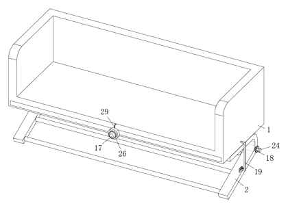
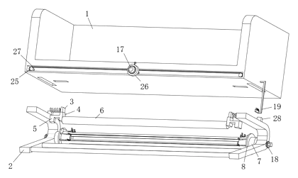
The mechanism relies on coordinated movement between the lamp plate, the sliding blocks, and the central support roller. The key components identified in the drawings include:
| No. | Part | What it does |
|---|---|---|
| 1 | Lamp Plate | The base structure holding the drive assembly and vertical grooves. |
| 2 | Support | The frame containing the rotating supporting roller and limit plates. |
| 3 | Sliding Block | Moves horizontally along the lamp plate’s channels to adjust holder position. |
| 4 | Lamp Holder | Fixed to the bottom of the sliding block; holds one end of the tube. |
| 5 | Driving Member | Attached to the lamp holder; interacts with the squeeze plates. |
| 6 | Lamp Tube | The replaceable UV or LED element being serviced. |
| 7 | Supporting Roller | Rotates inside the support to lift and guide the tube. |
| 8 | Squeeze Plates | Located at both ends of the roller; push the driving members to initiate rotation. |
| 9 | Placement Groove | Formed by the arc component; holds the tube after release. |
| 10 | Arc Component | Symmetrical arcs that form the lifting path for the tube. |
| 11 | Slide Bar | Connects the pressing plate to the cylinder mechanism. |
| 12 | Cylinder | Provides linear actuation force via springs. |
| 13 | Second Spring | Assists in returning the pressing plate to its original position. |
| 14 | Limit Plate | Prevents over-rotation of the supporting roller. |
| 15 | Lifting Plate | Slides within the opening of the limit plate to engage the cylinder. |
| 16 | Pressing Magnet | Permanent magnet inside the pressing plate. |
| 25 | Screw Rods | Part of the drive assembly; rotate to move the sliding blocks. |
| 26 | Rotating Rods | Connected to screw rods via chains; driven by the switch mechanism. |
| 27 | Chain Belts | Transfer rotational force from the rods to the screws. |
| 28 | Installation Blocks | Sleeved on screw threads to secure the support top. |
Operating steps
- Activation: The user engages the switch (17), which powers the electromagnet (second magnet 30) and initiates the drive assembly.
- Holder Retraction: The rotating rods (26) turn the screw rods (25). This causes the installation blocks (28) and attached supports to shift, moving the sliding blocks (3) outward. Consequently, the lamp holders (4) move away from the center.
- Roller Engagement: As the holders move, the driving members (5) interact with the squeeze plates (8) at the ends of the supporting roller (7). The magnetic attraction between the first magnet and the energized second magnet helps align the components.
- Tube Lifting: The squeeze plates push the driving members, causing the supporting roller (7) to rotate unidirectionally. The outer surface of the roller encircles the tube, pushing it upward into the placement groove (9) formed by the arc component (10).
- Locking: The lifting plate (15) and cylinder (12) mechanism ensures the tube stays in the groove while the electrical contacts are fully disengaged.
- Removal: The tube is now accessible and released from the sockets. The user can slide it out or lift it from the groove without touching hot metal parts directly.
Applications
Hotel Bathroom Upkeep
Housekeeping staff can replace UV bulbs in guest rooms quickly without waiting for the rack to cool completely. This maintains hygiene standards efficiently during turnover times.
Commercial Laundries
Large-scale laundry operations use heated towel cabinets to sanitize linens. Frequent bulb replacements are necessary for consistent UV output. This design minimizes equipment downtime during maintenance shifts.
Residential Smart Homes
High-end home automation systems integrate towel racks into smart hubs. Users appreciate the ease of self-service maintenance for built-in lighting and sterilization features without calling a technician.
Medical Facility Drying Units
Facility maintenance teams can evaluate the release mechanism for servicing towel-rack lamps. This description does not establish suitability for instrument sterilization or infection control; any such intended use requires separate validation.
Where it is less suitable
- Low-Cost Consumer Models: Basic towel racks without UV functions do not need this complex mechanical release system, making it too expensive for entry-level products.
- External Bulb Designs: Racks where the bulb is mounted externally and easily accessible do not benefit from this internal quick-release mechanism.
- Fixed-LED Integrated Boards: If the lighting is provided by soldered SMD LEDs rather than replaceable tube-style lamps, this structure cannot be applied.
Frequently asked questions
Why is a quick-release mechanism needed for towel rack lamps?
Electric towel racks generate significant heat. Traditional lamp tubes are hard to remove because they are wedged tightly between holders. Technicians often have to wait hours for the unit to cool down or risk burning their hands trying to pull the hot glass. This mechanism allows you to eject the tube mechanically without touching the hot ends, improving safety and maintenance speed.
Does this work with any type of lamp tube?
The patent describes a structure designed for cylindrical tubes like UV sterilization lamps or standard fluorescent/LED tubes. Compatibility depends on the diameter and length. You would need to customize the placement groove dimensions and the roller radius to fit specific tube sizes.
Is the mechanism difficult to install?
It is designed to be integrated into the towel rack’s chassis during manufacturing. For end-users, the operation is simple: activate the switch or drive assembly, and the tube lifts out automatically. However, initial setup requires precise alignment of the magnets and squeeze plates to ensure smooth rotation.
Can this be used for commercial laundry facilities?
Yes. Commercial laundries often have banks of heated towel cabinets. The ability to change bulbs quickly without powering down entire sections or waiting for cooling cycles makes this ideal for high-volume maintenance environments.
What happens if the magnets lose strength?
The design uses a combination of permanent magnets and electromagnets. Over time, permanent magnets in harsh humid environments may degrade. Regular inspection is recommended. The mechanical squeeze plates provide a backup physical engagement even if magnetic assistance weakens, though optimal performance relies on the magnetic alignment.
Is this patent active in the United States?
No. The patent CN116250750B is filed only in China. It is currently in force there. Since there are no US counterparts, you can generally manufacture and sell this specific design in the US, provided you do not infringe on other unrelated US patents regarding towel rack electronics or safety standards.
Can this design be made and sold in the US?
The patent was filed only in China and is currently in force there. It does not restrict manufacturing or sales in the US. However, electric towel racks are subject to strict electrical safety standards (such as UL) and potential FDA/EPA regulations if sterilization claims are made. We recommend a freedom-to-operate check for broader appliance patents before mass production.
Are you affiliated with the patent owner?
No. IP2M is an independent design and manufacturing service working from the public patent document.
Request a quote
Click Request a Quote below to see our email address - copy it, or open your email app with a ready-made message. Please mention patent CN116250750B in the subject.
Helpful details to include:
- Your company and channel (appliance brand, hotel supplier, commercial laundry provider)
- Target lamp tube specifications (diameter, length, voltage)
- Desired material for the rack body (aluminum, stainless steel, plastic)
- Automation level (manual crank vs. electronic motorized release)
- Estimated quantity and target price
- Timeline - when you would like samples and the first shipment
You can also reach us at (332) 203-9997.
Explore this product
Interested in building this?
Tell us your target market, quantity and timeline. We reply with options for prototyping, small-batch runs or volume production.
Send your inquiry to
Please put CN116250750B in the subject line and tell us your company, country, estimated quantity and timeline.
Prefer to talk? Call (332) 203-9997.
More product-ready patents
All Bath & Personal Care patents →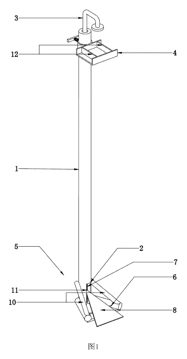
Bath & Personal Care
Foot-Pedal Soap & Sanitizer Dispenser Stand
Hands-free, battery-free dispenser stand - step on a pedal to press the pump of any soap or sanitizer bottle.
Patent CN207461995U
Bath & Personal Care
Ear-Shaped Mask Strap Guard with Tension Adjuster
Ear-shaped silicone guard and strap-length adjuster that make ear-loop masks comfortable to wear for long hours.
Patent CN205456233U
Bath & Personal Care
Adjustable-Length Back Scrubber Strap with Push-Button Handles
Back-scrubber strap with push-button handles that set its length and a spring that keeps it taut.
Patent CN207041452U
Bath & Personal Care
Angled-Plate Hair Straightener
Flat iron with plates twisted 45-75° to the handle, a curling groove and rubber-capped tips.
Patent CN206137462U
Bath & Personal Care
Refillable Lipstick Case with Sealed Snap-In Refill Pods
Reusable twist-up lipstick case; sealed refill pods unlock at the top of the stroke for shade swaps.
Patent CN206909979U
Bath & Personal Care
Quick-Release Toilet Seat Hinge with a Push-Button Two-Strip Latch
Toilet seat hinge: drop the shaft onto a grooved post to lock; one push parks the latch open to lift it off.
Patent CN210370292U
Browse by category
- Apparel & Accessories (33)
- Baby & Kids (24)
- Bags & Luggage (14)
- Bath & Personal Care (24)
- Car Accessories (19)
- Furniture, Bedding & Storage (18)
- Garden & Outdoor (26)
- Health & Wellness (11)
- Home, Kitchen & Cleaning (39)
- Lighting (18)
- Packaging & Containers (9)
- Pet Products (8)
- Phone & Camera Accessories (7)
- Retail Display (19)
- School, Office & Art (27)
- Sports & Recreation (33)
- Tools & Workshop (42)
- Toys & Games (18)
This page is based on the public patent document CN116250750B, assigned to Guangzhou Sabo Metal Product Co ltd. IP2M is an independent manufacturing service and is not affiliated with, endorsed by or licensed by the patent owner. Images marked as concept renderings are illustrations, not photos of an existing product. Patent status information is provided for reference only and is not legal advice; confirm freedom to operate for your market before production. Full disclaimer.