At a glance
| Patent number | CN116549985B (application CN202310665463) |
| Type | China invention patent (发明专利) - protects product shape, structure, and method |
| Original title | A splice plate and combination toy (一种拼接板及组合玩具) |
| Patent owner | Shenzhen Shengshi Jincheng Education Technology Co ltd |
| Inventors | Zhao Wei, Ye Yixiao, Chang Le |
| Filing date | 2023-06-06 |
| Grant date | 2025-03-28 |
| Status (China) | In force - valid until at most 2043-06-06, provided annual fees are paid |
| Patent family | Chinese filings only - no US, European, Japanese, PCT or other filings listed |
| Cited by | 0 later documents |
| Source | Google Patents (search for CN116549985B) |
What the claims cover, in plain language
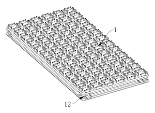
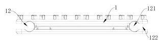
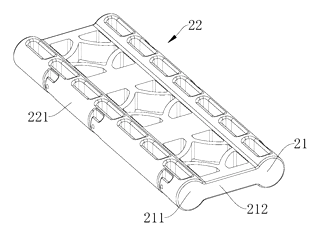
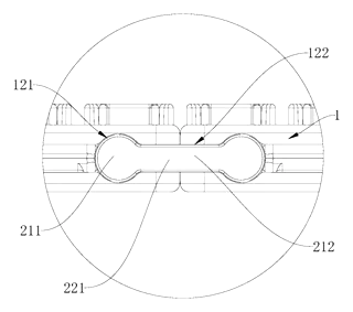
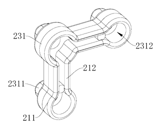
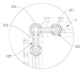
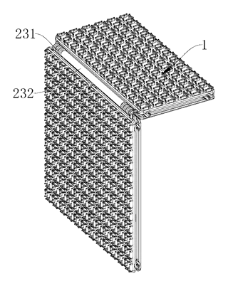
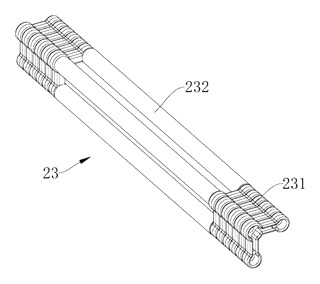
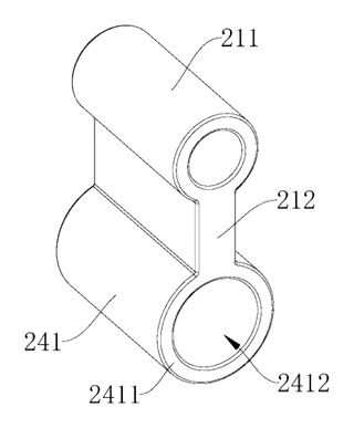
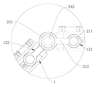
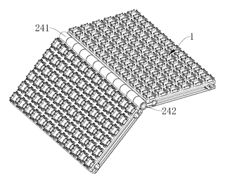
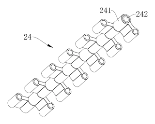
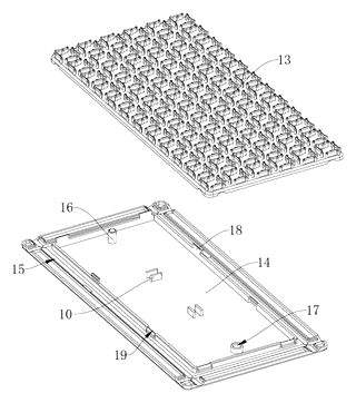
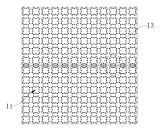
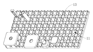
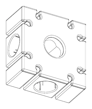
Claim 1 defines a splice plate featuring multiple clamping units for holding articles of different shapes and a connecting groove for mating with a connecting structure. The key innovation is that any two plates can be connected at any angle using this groove. The connecting structure includes blocks that insert into the groove for radial limiting. It specifies three modes: fixed horizontal/vertical connection via double-ended blocks, or a hinged connection using a hinge point and staggered insertion.
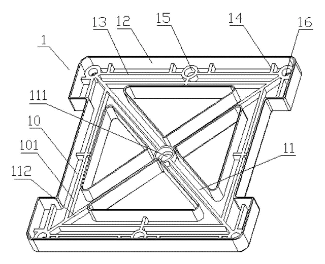
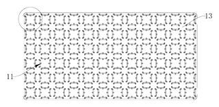
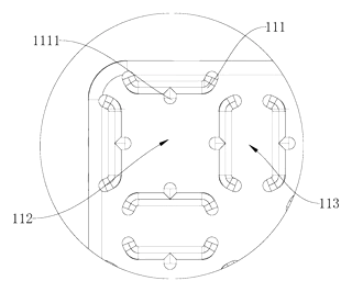
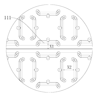
Claim 2 details the clamping units as square structures arranged transversely and longitudinally. It introduces a “first slot” for round articles within the unit and a “second slot” between adjacent units for kidney-shaped articles.
Claim 3 describes the mechanical specifics of the clamping: four limit strips forming the square, inward limit protrusions creating the first slot, and outward half-lip cross-sections. It notes that edge strips align with interior strips to maintain slot continuity across joined plates.
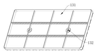
Claims 4-5 describe alternative plate configurations, including dual-body buckling mechanisms and positioning holes for wall mounting.
Claims 6-8 define the complete combination toy, specifying the exact geometry of the straight, L-shaped, and hinge-based connecting assemblies required to achieve the 3D structural capabilities described in Claim 1.
This is a simplified reading for orientation only. The legal scope is defined by the exact claim wording in the official Chinese document.
What this means for US production
This patent was filed only in China and is currently in force. Making or selling this specific design in China requires the owner’s permission. There is no US patent counterpart, meaning the technology itself is not restricted by this specific document in the United States.
Two points to settle early:
- Other patents may exist. Modular building systems are a crowded field. Major toy companies hold extensive portfolios regarding interlocking bricks, magnetic tiles, and snap-fit connectors. A freedom-to-operate (FTO) review is strongly recommended to ensure your specific implementation of the clamping grid and hinge mechanism does not infringe on active US patents in the general category of construction toys.
- Safety Standards. Unlike generic hardware, this is a consumer product intended for children. Compliance with ASTM F963 and CPSIA is mandatory and drives material selection and mold tolerances.
Customization and manufacturing
What can be customized
| Area | Options |
|---|---|
| Material | ABS, PP, or PC blends for impact resistance and flexibility |
| Color | Pantone-matched injection colors; pad printing for logos/instructions |
| Connector Types | Additional custom connector shapes (e.g., T-joints, curved rails) compatible with the same groove profile |
| Clamp Density | Adjust grid spacing to accommodate larger or smaller accessories |
| Finish | Matte, glossy, or textured surface treatments |
Things to plan for (US market)
- ASTM F963-23: Standard Consumer Safety Specification for Toy Safety. Critical for small parts, sharp edges, and material toxicity.
- CPSIA: Requires testing for lead, phthalates, and tracking labels for products intended for children under 12.
- Small Parts Regulation: If marketed for ages <3, strict size limits apply to detachable components. The clamping units must retain accessories securely to prevent choking hazards.
How a project runs
- Inquiry - Define target age group, color palette, and quantity.
- Design - Finalize mold flow analysis for thin-wall clamping lips and connector tolerances.
- Prototype - 3D-printed samples for fit checks and drop tests.
- Pilot Run - Injection molding trial to verify ejector pin marks and cosmetic finish.
- Production - Mass injection molding, assembly, and safety certification testing.
Quantities & timeline
Tooling for multi-cavity molds is significant due to the complexity of the undercuts in the clamping units. Lead times depend on mold fabrication and safety testing cycles. Send us your design specifications, target retail price, and estimated annual volume and we will reply with options.
Production notes
Tooling and process
Injection molding is the likely primary process, requiring precision molds to handle the intricate half-lip structures of the clamping units. Multi-cavity tooling is typical to manage unit costs.
Cost drivers
The number of molds is typically a major cost driver, especially if different connector types require separate toolsets. Print colors for instructional markings also add setup costs. Material grade impacts pricing based on impact requirements.
Prototyping path
Typically, prototyping starts with a 3D-printed sample to validate the snap-fit engagement of the connectors. Follow with a functional sample using soft tooling or initial aluminum molds before committing to steel production.
What we would change before tooling
We would likely adjust the draft angles on the inner limit protrusions to prevent sticking during ejection. Ensuring consistent wall thickness in the half-lip sections is critical to avoid warping.
Common failure points
Cracking after drops is a risk if the polymer is too brittle. Magnet strength is irrelevant here, but paint wear on high-contact clamp surfaces could occur. Hinge boss wear depends on the final material choice.
Patent drawings
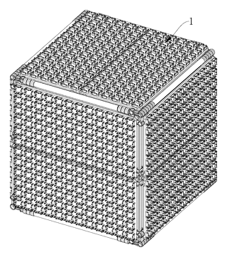
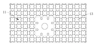
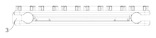
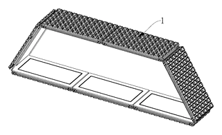
Drawings reproduced from the public patent document for reference.