
Patent CN116831876B
Updated November 5, 2026Exoskeleton Auxiliary Cradle with Seat-Following Hover Support
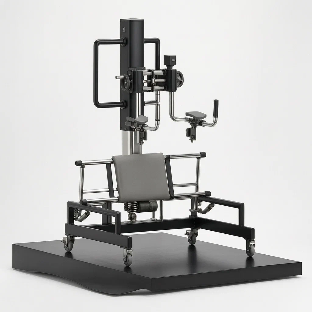
Standard exoskeleton training often requires separate chairs or manual adjustments when users sit down or stand up, leading to instability and awkward transfers. This auxiliary cradle solves this by integrating a 'seat-following' hover support directly into the lifting frame. When the exoskeleton robot lifts the user, the seat automatically retracts upward and inward, clearing space while supporting the buttocks. When lowering, it extends downward and outward to catch the user. The connection mechanism uses dual stiffness springs and linear bearings to absorb shocks, ensuring a safe, smooth transition between sitting and standing positions without manual intervention.
- China invention patent - in force
- No filings outside China
- Rehabilitation equipment
- Carbon steel tubes, linear bearings, electric push rods
Splat! What let you down?
🪑
Seat-Following Motion
The seat retracts and deploys in linkage with the upper post's vertical movement.
⚙️
Dual Stiffness Connection
First and second stiffness springs with linear bearings absorb shocks during transfer.
📏
Sensing Module
Acquires displacement data to control the seat electric push rod precisely.
🦵
Hover Support Angle
Maintains a positive correlation between hovering angle and thigh-trunk angle.
Bring this product to market
- ✓ Patent review Patent family and legal status reviewed in the relevant jurisdictions.
- 2 Product brief · now How it works, uses and options written up
- 3 Prototype First samples for buyers to review
- 4 Pilot run Small first batch for launch customers
- 5 Volume production Repeat orders at scale
Buyer interest
– of 100 buyers needed to start prototyping
One click, no sign-up. Each vote is one real visitor, and products with the most interest go to prototyping first.
Build team: no members yet. Need a partner, co-funding or skills to build this? Join and we introduce the team once it forms.
Patent Rights & Team Participation
Before joining a development team, participants should ensure they have the necessary rights or authorization to participate in the project.
Participation is generally appropriate where:
- You own the relevant patent rights or have obtained permission or a license from the rights holder.
- The relevant patent rights have expired or have been legally invalidated in the jurisdictions where the planned activities will take place.
- The planned development, manufacturing, and commercialization activities have been independently assessed and do not infringe applicable patent rights in the relevant jurisdictions.
Important: Being located outside a country where a patent is protected does not automatically exempt you from patent infringement risks. Patent rights may apply based on where development, manufacturing, use, sale, or import activities take place.
IP2M does not grant any patent license or authorization through team participation. Joining a project does not provide permission to use, manufacture, or commercialize patented technology.
The problem
In traditional exoskeleton rehabilitation setups, the patient often sits on a separate chair before being strapped into the robotic frame. Transferring between the chair and the suspended exoskeleton harness is physically demanding and can be unstable. If the support structure does not move with the patient’s center of gravity during the sit-to-stand transition, there is a risk of sudden drops or awkward leverage on the spine. Furthermore, static frames do not adjust to the varying heights required for different phases of therapy, forcing therapists to manually intervene frequently.
The solution
This patent describes an exoskeleton auxiliary cradle that integrates a dynamic seat directly into the lifting mechanism.
- A movable chassis (1) with sliding wheels forms the base.
- A lifting part consists of a lower upright and an upper upright that slides vertically along it.
- An exoskeleton connecting mechanism attaches to the upper upright, using a bolt block, linear bearing, and two springs of different stiffness to connect to the exoskeleton robot.
- A seat portion is mounted on a support frame fixed to the chassis. It includes front and rear seat rods with rollers running on guide rails.
- A link mechanism with a seat electric push rod drives the seat.
- A sensing module detects the vertical displacement of the upper upright.
- Control equipment links the seat movement to the lift: as the user stands (upper upright rises), the seat retracts upward; as the user sits (upper upright lowers), the seat deploys downward.
Who it is for
- Rehabilitation Centers: Facilities treating spinal cord injury or stroke patients who need assisted sit-to-stand training.
- Physical Therapy Clinics: Therapists requiring stable, adjustable support structures for gait training sessions.
- Elderly Care Homes: Institutions looking for safer transfer aids for residents with limited mobility.
- Medical Equipment Manufacturers: Brands seeking to add intelligent, linked-motion features to their existing exoskeleton product lines.
How it works
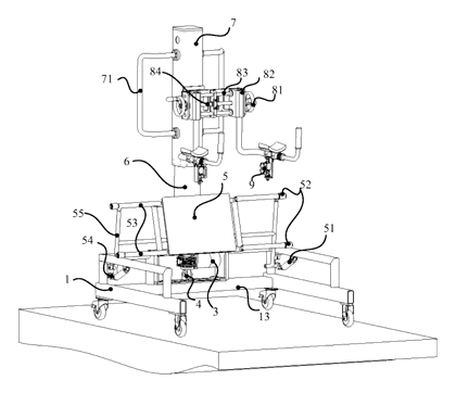
The main parts
| No. | Part | What it does |
|---|---|---|
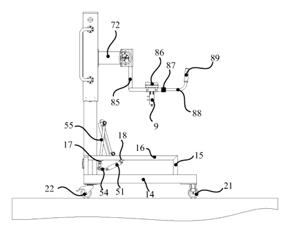
| 1 | Movable Chassis | Base with hollow carbon steel tubes and sliding wheel set. |
| 13, 14 | Bearing/Connecting Arms | Structural frame components welded together. |
| 21, 22 | Directional/Universal Wheels | Allow the unit to be moved and positioned. |
| 16 | Chassis Upper Layer Rod | Guide rail for the seat rollers. |
| 53 | Seat Mechanism | Front and rear rods with cushion, moving on rollers. |
| 54 | Link Mechanism | Electric push rod, rocker, and connecting rod driving the seat. |
| 3 | Lifting Part | Lower and upper uprights allowing vertical adjustment. |
| 4 | Exoskeleton Connection | Bolt base, springs, and linear bearing attaching to the robot. |
| 5 | Sensing Module | Measures displacement of the upper upright. |
| 6 | Control Equipment | Processes sensor data to drive the seat push rod. |
Operating Steps
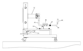
- Initial State: The patient sits on the extended seat mechanism. The exoskeleton robot is connected via the bolt block and spring system on the upper upright.
- Sit-to-Stand Transition: The patient activates the exoskeleton to rise. The upper upright moves up along the lower upright.
- Sensing and Control: The sensing module detects the upward displacement. The control equipment calculates the required retraction distance for the seat electric push rod.
- Seat Retraction: The push rod contracts, rotating the seat rocker. This pulls the rear seat rod, causing the entire seat mechanism to slide horizontally toward the upper upright and roll upward along the guide rails.
- Support Maintenance: Throughout the motion, the seat maintains contact with the patient’s buttocks, providing a “hovering” support that adjusts its angle relative to the thigh and trunk.
- Stand-to-Sit Transition: To return to the seated position, the upper upright descends. The control system extends the seat push rod, deploying the seat downward and outward to safely receive the patient.
Applications
Spinal Cord Injury Rehabilitation
According to the patent, the cradle is designed to support the pelvis during assisted standing exercises, which may reduce the fear of falling and allow therapists to focus on gait patterns rather than balance management.
Post-Stroke Gait Training
Stroke survivors frequently exhibit asymmetrical weight distribution. According to the patent, the seat-following mechanism is designed to provide consistent pelvic support during repetitive sit-to-stand drills, which may help retrain biomechanics without manual spotting.
Elderly Mobility Assistance
For elderly individuals with weak leg muscles, the automatic seat deployment is described as reducing the risk of sudden drops when they attempt to sit after standing. According to the patent, the dual-stiffness spring connection is designed to absorb minor jerks, which may improve comfort.
Clinical Research Settings
Researchers studying human-exoskeleton interaction require precise control over support points. The sensing module allows for data logging of displacement and force feedback, useful for analyzing how assistive devices affect joint loads.
Where it is less suitable
- High-Intensity Athletic Training: Athletes typically perform dynamic movements without external pelvic support; this device is designed for controlled, therapeutic transfers.
- Home Use Without Space: The chassis footprint and lifting column height require significant floor space and ceiling clearance, making it unsuitable for small apartments.
- Users Requiring Full Body Suspension: This is an auxiliary cradle; it still requires a compatible exoskeleton robot to bear the primary body weight.
Patent & Production
At a glance
| Patent number | CN116831876B (application CN202310813534) |
| Type | China invention patent (发明专利) - protects method and structure |
| Original title | Exoskeleton auxiliary cradle for seat-following hover support (一种座椅随动悬停支撑的外骨骼辅助吊架) |
| Patent owner | Chongqing Biological Intelligent Manufacturing Research Institute |
| Inventors | Cheng Ke, Meng Jiang, Liu Wenbin, Wu Wenjie, Zuo Taoqiang, Qiu Biquan, Xie Haiqiong |
| Filing date | 2023-07-04 |
| Grant date | 2024-12-17 |
| Status (China) | In force - valid until at most 2043-07-04, provided annual fees are paid |
| Patent family | Public record shows Chinese filings only - no US, European, Japanese, PCT or other filings listed |
| Cited by | 0 later documents |
| Source | Google Patents (search for CN116831876B) |
What the claims cover, in plain language
Claim 1 defines the core structure: a movable chassis, a seat portion, a lifting portion, a sensing module, and control equipment. The key feature is the linkage: the control equipment adjusts the seat electric push rod based on the displacement of the upper upright, so the seat retracts or deploys in sync with the vertical lift. It specifies a connection mechanism with a first stiffness spring and a second stiffness spring (where the first is smaller than the second) arranged around a linear bearing.
Claim 2 adds a guide rail on the support frame with sliding blocks at the ends of the front seat rod. Claim 3 specifies an upright electrical push rod connected to the upper upright. Claim 4 states that the upright push rod is driven by a stepper motor. Claim 5 introduces an exoskeleton width adjustment device with a support rail. Claim 6 details the width adjustment using an armrest slider and hand screw. Claim 7 describes the L-shaped handle and wedge-type clamping mechanism for the armrest. Claim 8 adds a forearm support cushion on the support rail.
This is a simplified reading for orientation only. The legal scope is defined by the exact claim wording in the official Chinese document.
What this means for US production
This patent was filed in China and is currently in force. Making or selling this specific configuration in China would require the owner’s permission. However, the public record shows no US counterpart. Therefore, producing or selling this design in the United States is not restricted by this specific Chinese patent document alone.
Two points to settle early:
- Other patents may exist. Exoskeletons and rehabilitation robotics are a crowded field with numerous active patents held by major medical device companies (e.g., Ekso Bionics, Cyberdyne, ReWalk). These patents may cover similar seat-following mechanisms or spring-loaded connections. A freedom-to-operate (FTO) review is strongly recommended before mass production.
- Sensor Calibration. The control logic relies on precise displacement measurement. Variations in sensor placement or motor response times could affect the “hovering angle” correlation described in Claim 1.
Customization and manufacturing
What can be customized
| Area | Options |
|---|---|
| Chassis Size | Wheelbase and tube dimensions to fit different room sizes |
| Load Capacity | Steel thickness and motor torque for heavier users |
| Seat Material | Medical-grade foam density and upholstery fabric |
| Spring Rates | Stiffness values for the first and second springs to tune shock absorption |
| Connectors | Bolt patterns to match specific exoskeleton robot brands |
| Controls | User interface layout and emergency stop placement |
Things to plan for (US market)
- FDA Registration: While this is an accessory, if marketed for medical use, the final system may fall under Class I or II medical device regulations depending on intended use claims.
- Electrical Safety: UL 60601-1 standards apply to medical electrical equipment, covering leakage currents and insulation.
- Battery Compliance: If battery-powered, UN 38.3 transport testing and FCC Part 15 emissions compliance are required.
- Labeling: Clear warnings regarding pinch points in the seat linkage and maximum user weight limits.
How a project runs
- Inquiry - Define target user weight, exoskeleton compatibility, and facility size.
- Design - Finalize linkage geometry, spring rates, and control algorithm parameters.
- Prototype - Build functional samples with off-the-shelf motors and sensors for motion testing.
- Validation - Test displacement accuracy and shock absorption under load.
- Production - Weld chassis, assemble mechanics, install electronics, and calibrate controls.
Quantities & timeline
Tooling involves welding jigs for the chassis, molds for plastic housings, and custom fabrication for the metal seat rods. Electronics assembly requires SMT lines for control boards. Certification tests for electrical safety take several weeks. Send us your target specifications, quantity, and timeline and we will reply with options.
Production notes
Tooling and process
Welding fixtures are typically needed for the carbon steel chassis tubes. Injection molding tools are required for any plastic covers or handles. Motor and sensor integration involves precise alignment steps.
Cost drivers
Motor selection and sensor integration typically affect costs. Skin-contact material grade for the cushion affects both price and regulatory approval. Sealing components to prevent dust ingress add complexity.
Prototyping path
Start with a 3D-printed housing for the control unit. Off-the-shelf motors and linear guides are typically used for initial mechanical validation. Perform thermal and vibration tests on the assembled prototype before tooling.
What we would change before tooling
We would likely verify the shaft and bearing alignment tolerance to ensure smooth seat movement. Check the thread engagement strength of the bolt connectors under cyclic loading. Confirm the hinge boss design for wear resistance.
Common failure points
Vibration loosening of fasteners is a risk due to motor operation. Spring fatigue may alter the stiffness ratio over time. Cleaning difficulty arises if crevices in the linkage trap debris. Ensure wall thickness and joint design prevent cracking under heavy loads.
Patent drawings
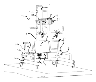
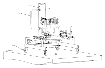
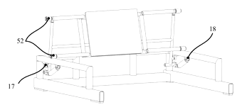
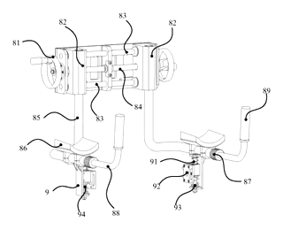
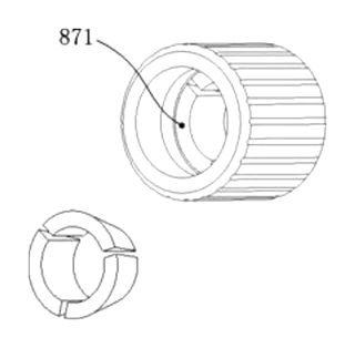
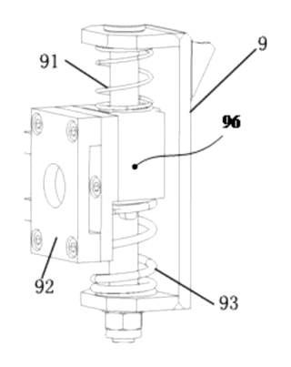
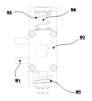
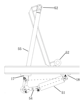
Drawings reproduced from the public patent document for reference.
Frequently asked questions
How does the seat follow the user?
The system uses a sensing module to measure the vertical movement of the upper lifting post. The control equipment then drives the seat electric push rod to retract or extend the seat mechanism proportionally. This keeps the seat supporting the user’s buttocks throughout the sit-to-stand transition.
Is it compatible with all exoskeleton robots?
Not necessarily. The patent describes a generic bolt-connecting base. Compatibility depends on matching the bolt pattern and weight capacity of your specific exoskeleton robot. We recommend checking the mounting interface specifications.
What happens if the power fails?
The design includes mechanical stops and friction-based linear bearings. In a power loss scenario, the seat mechanism typically holds its position, though it may slowly drift depending on the brake type used in the electric push rod. Manual release valves can be added for emergency lowering.
Can the seat width be adjusted?
Yes, according to Claims 5-7, the design includes a width adjustment device with an armrest slider and a hand screw mechanism, allowing the support area to be customized for different user sizes.
How much weight can the cradle support?
The patent does not specify a maximum load rating. Load capacity is determined by the structural integrity of the carbon steel tubes, the torque of the electric push rods, and the quality of the linear bearings during the design phase.
Is this a medical device?
It is an auxiliary component for exoskeleton systems. Its regulatory classification depends on the final marketing claims and integration with the primary exoskeleton device. It should be treated as part of a medical rehabilitation system.
Can this design be made and sold in the US?
The patent is filed in China and is in force there. However, the public record shows no US counterpart. Therefore, this specific Chinese patent does not restrict manufacturing or sales in the US. Please note that other US patents may cover similar technologies, so a freedom-to-operate check is advised.
Are you affiliated with the patent owner?
No. IP2M is an independent design and manufacturing service working from the public patent document.
Request a quote
Click Request a Quote below to see our email address - copy it, or open your email app with a ready-made message. Please mention patent CN116831876B in the subject.
Helpful details to include:
- Your company and channel (rehab center supplier, medical device integrator, research lab)
- Target user weight and height range
- Exoskeleton model you intend to pair with
- Power requirements (AC mains, battery backup)
- Estimated quantity and target price
- Timeline - when you would like prototypes and the first shipment
You can also reach us at (332) 203-9997.
Page editor: Emily Zhang, Product Editor · IP2M
Last updated November 5, 2026. If something on this page looks wrong, email [email protected] and we will check it against the patent.
Interested in building this?
Tell us your target market, quantity and timeline. We reply with options for prototyping, small-batch runs or volume production.
Send your inquiry to
Please put CN116831876B in the subject line and tell us your company, country, estimated quantity and timeline.
Prefer to talk? Call (332) 203-9997.
More product-ready patents
All Health & Wellness patents →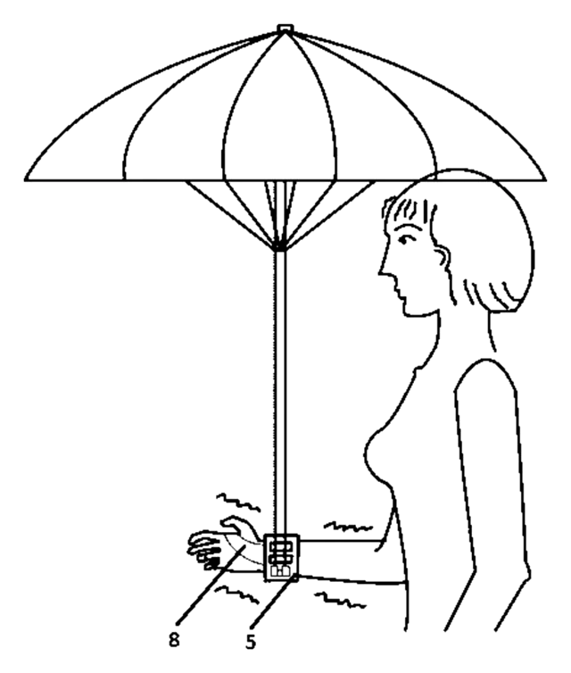
Health & Wellness
Wrist-Mounted Umbrella Stabilizer
Wrist-worn umbrella holder with an anti-shake link; the patent designs it for people with tremor.
Patent CN212545964U
Health & Wellness
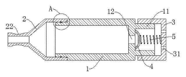
Spring-Valve Breath Trainer for Singers
Pocket breath trainer: blow against a spring-loaded valve to practice breath support for singing.
Patent CN207833725U
Health & Wellness
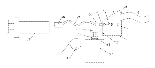
Closed-Loop Nasal Rinse Kit with Collection Bottle
Nasal rinse set: syringe-fed nose plug inside a sealed hood, with used solution drawn into a bottle.
Patent CN208017763U
Health & Wellness
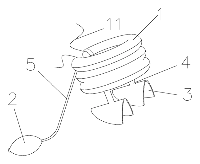
Inflatable Cervical Traction Collar Shaped for a Child's Neck
Child-size three-ring air collar on telescoping shoulder struts, inflated with a hand bulb.
Patent CN208958444U
Massage & Wellness
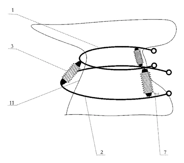
Pneumatic Multi-Directional Neck Traction Collar
Three-airbag cervical collar that inflates in sequence to guide the head in multiple directions.
Patent CN207202980U
Health & Wellness
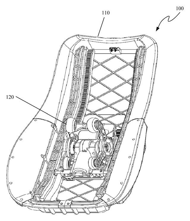
Shoulder-Detecting Massage Chair Mechanism with Forked Swing Arms
Massage chair core uses forked swing arms and sensors to detect shoulders and adjust the routine.
Patent CN106618998B
Browse by category
- Apparel & Accessories (41)
- Baby & Kids (27)
- Bags & Luggage (15)
- Bath & Personal Care (28)
- Car Accessories (23)
- Furniture, Bedding & Storage (21)
- Garden & Outdoor (29)
- Health & Wellness (13)
- Home, Kitchen & Cleaning (44)
- Lighting (22)
- Packaging & Containers (11)
- Pet Products (10)
- Phone & Camera Accessories (8)
- Retail Display (23)
- School, Office & Art (32)
- Sports & Recreation (41)
- Tools & Workshop (50)
- Toys & Games (21)
This page is based on the public patent document CN116831876B, assigned to Chongqing Biological Intelligent Manufacturing Research Institute. IP2M is an independent manufacturing service and is not affiliated with, endorsed by or licensed by the patent owner. Images marked as concept renderings are illustrations, not photos of an existing product. Patent status information is provided for reference only and is not legal advice; confirm freedom to operate for your market before production. Full disclaimer.