
Patent CN116853757B
Updated October 27, 2026Motorized Linear Tool Storage Device for Industrial Tapping Machines
Fixed tool racks on industrial silicon tapping machines take up floor space and make it difficult to position tools accurately when room is tight. This design replaces the fixed rack with a movable one mounted on a base. A driving device pushes the tool rack along a guide rail so that different tools line up automatically with the machine's pickup point. The translation mechanism uses symmetrical sliding rails and blocks, with limiting rods fitting into limiting seats equipped with damping pads to control travel. Tools are held in clamps on bearing plates attached to support frames, keeping them parallel and organized. By automating the alignment, the system reduces positioning errors caused by manual rotation and fits into compact workspaces.
- China invention patent - in force
- No filings outside China
- Workshop storage
- Servo motor, ball screw, linear rails, steel frames
Splat! What let you down?
⚙️
Motorized linear drive
A servo motor and ball screw move the tool rack along a guide rail for precise positioning.
🛤️
Guided translation
Symmetrical sliding rails and blocks with limiting rods and damping pads control the travel path.
🔧
Parallel tool arrangement
Multiple tools are held side-by-side in clamps on bearing plates, aligned along the travel direction.
🔄
Drive options
The system can use a servo motor, hydraulic cylinder, telescopic cylinder, or chain/rack transmissions.
Bring this product to market
- ✓ Patent vetted China-only family and legal status checked
- 2 Product brief · now How it works, uses and options written up
- 3 Prototype First samples for buyers to review
- 4 Pilot run Small first batch for launch customers
- 5 Volume production Repeat orders at scale
Buyer interest
– of 100 buyers needed to start prototyping
One click, no sign-up. Each vote is one real visitor, and products with the most interest go to prototyping first.
Build team: no members yet. Need a partner, co-funding or skills to build this? Join and we introduce the team once it forms.
The problem
Industrial silicon tapping machines require several different tools during operation. Traditional setups use a fixed tool rack that occupies a large footprint on the factory floor. In facilities where space around the furnace is limited, installing a bulky stationary rack is difficult. Furthermore, rotating a fixed rack to bring the correct tool into position often leads to inaccurate alignment. Operators must manually adjust the tools, which increases installation difficulty and slows down the tapping process. The overall size of conventional racks restricts where the tapping machine can be deployed, reducing its usefulness across different plant layouts.
The solution
This patent describes a tool storage device that solves these spatial and alignment issues through linear motion rather than rotation.
- A base (4) is fixed in place, and a guide rail extending along a first direction is mounted on it.
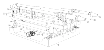
- A tool rack sits on the base, with its lower part engaged with the guide rail. The upper part holds a first tool (32), a second tool (33), and a third tool (34) arranged in parallel along the same direction.
- A driving device has its fixed part mounted on the base, while its output part connects to the tool rack to push it along the guide rail.
- A translation mechanism beneath the rack uses symmetrical sliding rails and sliding blocks (14) to support the movement smoothly.
- Limiting rods on the sliding blocks insert into limiting seats on the base, which contain damping pads inside their limiting holes to absorb impact at the ends of travel.
Who it is for
- Industrial silicon smelters that operate tapping machines in confined spaces around furnaces and need to reduce the equipment footprint.
- Heavy machinery integrators building automated tapping systems who require precise, repeatable tool alignment without rotational mechanisms.
- Plant engineering contractors tasked with retrofitting older furnace floors where floor space is already constrained by existing infrastructure.
- Custom automation builders designing linear tool changers for heavy-duty processing equipment in metals or materials handling.
How it works
The main parts
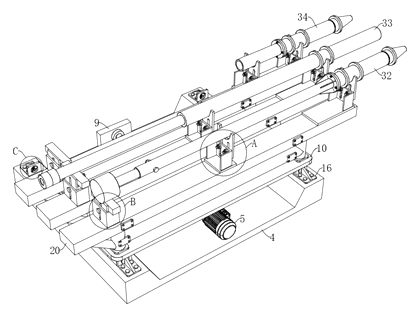
| No. | Part | What it does |
|---|---|---|
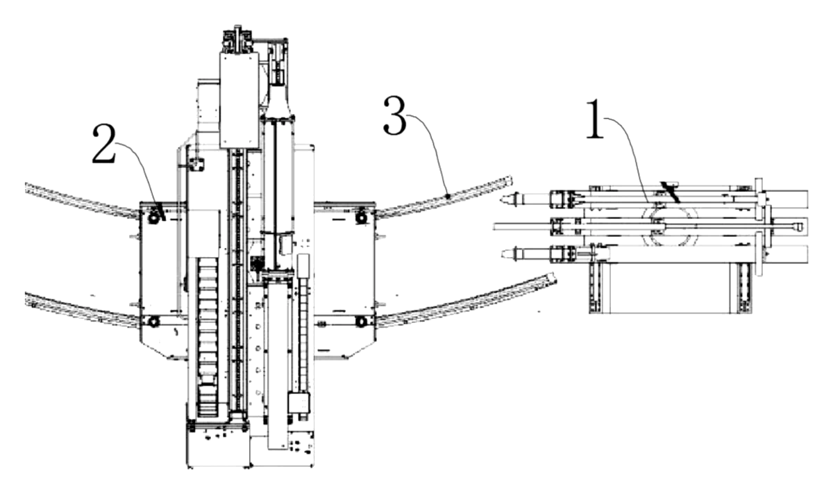
| 2 | Tapping machine | The industrial silicon tapping machine that retrieves the tools. |
| 4 | Base | The fixed foundation that carries the guide rails and limiting seats. |
| 10 | Bottom plate | The foundation of the moving tool rack, supported by the sliding blocks. |
| 14 | Sliding block | Connects the bottom plate to the sliding rails for linear movement. |
| 19 | Support frame | Three frames fixed on the bottom plate to hold the bearing plates. |
| 20 | Bearing plate | Mounted on top of the support frames to carry the tools. |
| 22 | Clip | Clamping mechanisms on the support frames to secure the tools. |
| 32, 33, 34 | First, second, third tools | The processing tools placed in parallel on the clips. |
Operating steps
- Initialization - The tool rack rests on the base with the sliding blocks engaged in the sliding rails. The driving device is idle.
- Selection - The control system determines which tool (e.g., the second tool) needs to align with the tapping machine’s pickup position.
- Actuation - The servo motor turns, driving the ball screw through the coupler. The threaded block moves along the screw, pushing the connecting block and the bottom plate.
- Translation - The entire tool rack slides along the guide rail. The limiting rods travel toward the limiting seats.
- Damping and stopping - The limiting rods enter the limiting holes, pressing against the damping pads to decelerate the rack smoothly without bouncing.
- Retrieval - The selected tool is now positioned exactly at the taking and placing station of the tapping machine for use.
Applications
Silicon furnace tapping floors
Smelting plants operate tapping machines directly adjacent to high-temperature furnaces where floor space is severely restricted. A linear tool rack slides parallel to the machine instead of swinging outward, allowing operations in narrow aisles. This prevents interference with nearby cooling lines or structural columns.
Automated heavy-material processing
Facilities processing industrial silicon or similar materials require frequent tool changes during a single tapping cycle. The motorized drive aligns the next tool automatically based on the programmed sequence. This removes the need for manual rotation and reduces alignment errors that could damage the tapping equipment.
Retrofitting older plant layouts
Older smelting facilities often lack the open floor plans required by modern rotating tool carousels. Installing this base-mounted linear rack allows plant engineers to upgrade automation without demolishing existing walls or relocating heavy furnace structures. The compact footprint fits into legacy workspaces.
Custom heavy-duty automation cells
Machine builders designing specialized processing cells for metal extraction can integrate this storage device as a modular component. The parallel arrangement of tools simplifies the programming of the picking robot or tapping arm. Builders can specify the number of support frames to match the exact tool count required.
Where it is less suitable
- Light-duty CNC machining centers - Standard rotary tool magazines are faster and more common for small cutting tools in enclosed CNC environments.
- Mobile service vehicles - The fixed base and guide rail system is designed for stationary industrial floors, not for transport in vibrating vehicles.
- Hand-tool workshop storage - This is an automated, motor-driven system for heavy industrial tools, not a cabinet for manual mechanic wrenches.
Frequently asked questions
How does the tool rack move?
The rack moves linearly along a guide rail on a fixed base. In the primary embodiment, a servo motor turns a ball screw via a coupler. A threaded block on the screw pushes a connecting block attached to the bottom plate of the tool rack, sliding it forward or backward.
What types of drives are available?
The patent describes several options. You can use a servo motor with a ball screw, a hydraulic cylinder, a telescopic cylinder, a hydraulic motor paired with a chain wheel transmission assembly, or a standard motor paired with a rack transmission assembly. The choice depends on the facility’s power supply and speed requirements.
How many tools can it hold?
The detailed description shows three support frames holding a first, second, and third tool in parallel. However, the patent notes that the number of carrying tools is not strictly limited to three; more or fewer tools can be placed by adjusting the number of support frames and clips in design.
How does it stop accurately without crashing?
The translation mechanism includes limiting rods fixed to the sliding blocks. As the rack reaches the end of its allowed travel, these rods plug into limiting holes in limiting seats mounted on the base. Inside those holes, damping pads absorb the kinetic energy to stop the rack smoothly.
Does it rotate like a carousel tool changer?
No. The entire purpose of this design is to replace rotating mechanisms with linear translation. The tools are arranged in parallel along the first direction, and the rack slides back and forth to align the correct tool with the tapping machine’s pickup point.
What keeps the tools from falling out during movement?
Clamping mechanisms, referred to as clips, are arranged at the top ends of the support frames along the length direction. These clips are matched to bear and secure the tools while the bottom plate translates along the sliding rails.
Can this design be made and sold in the US?
The patent was filed only in China and has no US or other foreign counterpart, so it does not restrict making or selling the design in the US. However, because it is in force in China until at most 2043-08-23 (if annual fees are paid), manufacturing it there requires the owner’s permission. Linear automation and tool changing mechanisms may be covered by other US patents - see Patent & Production - so we recommend a freedom-to-operate check before volume production.
Are you affiliated with the patent owner?
No. IP2M is an independent design and manufacturing service working from the public patent document.
Request a quote
Click Request a Quote below to see our email address - copy it, or open your email app with a ready-made message. Please mention patent CN116853757B in the subject.
Helpful details to include:
- Your company and channel (smelter, machinery integrator, automation builder)
- Tool dimensions and weights to be stored
- Number of tool stations required
- Preferred drive type (servo/ball screw, hydraulic, etc.)
- Required stroke length and available floor space
- Estimated quantity and target price
- Timeline - when you would like samples and the first shipment
You can also reach us at (332) 203-9997.
Explore this product
Interested in building this?
Tell us your target market, quantity and timeline. We reply with options for prototyping, small-batch runs or volume production.
Send your inquiry to
Please put CN116853757B in the subject line and tell us your company, country, estimated quantity and timeline.
Prefer to talk? Call (332) 203-9997.
More product-ready patents
All Tools & Workshop patents →
Tools & Workshop
Rolling Tool Box with Telescoping Step Ladder
Telescoping A-frame ladder with an attached rolling tool box that slides to your working height.
Patent CN206290197U
Tools & Workshop
Folding 3-Handle Wrench Multi-Tool
Folding three-handle wrench multi-tool with magnetic screwdriver bits, saw, file and bottle opener.
Patent CN205290875U
Tools & Workshop
Rolling Auto-Repair Tool Cabinet with Built-In Lights
Lockable rolling tool cabinet for car repair with interior lights, a lubricant tray, parts drawers and a tool bay.
Patent CN205989314U
Tools & Workshop
Wide-Opening Folding Bolt Cutter
Bolt cutter with linked, gear-meshing handles that open up to 190° and fold in half for storage.
Patent CN207206226U
Tools & Workshop
Nail-Holding Hammer with Fold-Out Drivers
Hammer with a nail-holding T-slot in the head and fold-out drivers stored in the handle.
Patent CN205254927U
Tools & Workshop
Modular Wrench with Screw-On Heads
Wrench handle with a three-way threaded hub for screw-on adjustable and hex heads, plus a pipe sleeve.
Patent CN206216564U
Browse by category
- Apparel & Accessories (22)
- Baby & Kids (16)
- Bags & Luggage (9)
- Bath & Personal Care (16)
- Car Accessories (10)
- Furniture, Bedding & Storage (12)
- Garden & Outdoor (18)
- Health & Wellness (8)
- Home, Kitchen & Cleaning (24)
- Lighting (12)
- Packaging & Containers (6)
- Pet Products (6)
- Phone & Camera Accessories (4)
- Retail Display (13)
- School, Office & Art (19)
- Sports & Recreation (25)
- Tools & Workshop (27)
- Toys & Games (12)
This page is based on the public patent document CN116853757B, assigned to Suzhou Langxin Intelligent Technology Co ltd. IP2M is an independent manufacturing service and is not affiliated with, endorsed by or licensed by the patent owner. Images marked as concept renderings are illustrations, not photos of an existing product. Patent status information is provided for reference only and is not legal advice; confirm freedom to operate for your market before production. Full disclaimer.