At a glance
| Patent number | CN116853757B (application CN202311066873) |
| Type | China invention patent (发明专利) - protects product shape, structure, and methods |
| Original title | Tool storage device and walking equipment (工具存放装置及行走设备) |
| Patent owner | Suzhou Langxin Intelligent Technology Co ltd |
| Inventors | Lu Shunkui, Zhong Haisheng, Xu Xiaowei, Lei Yangyang, Li Jiao |
| Filing date | 2023-08-23 |
| Grant date | 2024-01-30 |
| Status (China) | In force in China until at most 2043-08-23 (if annual fees are paid) |
| Patent family | Chinese filings only - no US, European, Japanese, PCT or other filings listed |
| Cited by | 0 later documents |
| Source | Google Patents (search for CN116853757B) |
What the claims cover, in plain language
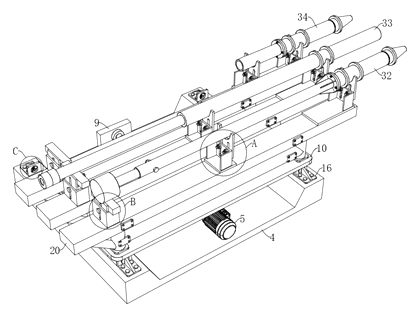
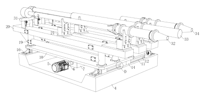
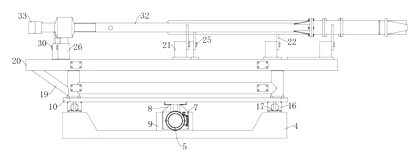
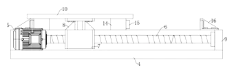
Claim 1 - A tool storage device comprising a fixed base with a guide rail extending in a first direction. A tool rack is arranged on the base, with its lower part matching the guide rail and its upper part holding multiple tools in parallel. A driving device has a fixed part on the base and an output part connected to the tool rack to move it along the rail. The tool rack has a bottom plate, three supporting frames fixed on top, and bearing plates fixed to the frames to hold a first, second, and third tool. A translation mechanism supports the bottom plate, using two symmetrical sliding rails on the base and sliding blocks connected to the bottom plate. Limiting blocks are on the sliding blocks, engaging sliding grooves in the rails. Limiting rods on the blocks plug into limiting holes in limiting seats on the base, which have damping pads. The driving device includes a servo motor connected to a ball screw via a coupler; the ball screw connects to a fixing plate on the base, and a threaded block on the screw connects via a connecting block to the bottom plate.
Claim 2 - Linear guide rails are at both ends of the base in the length direction, with sliding blocks at the bottom of the tool rack; the driving device is in the middle of the base. Claim 3 - The tool rack includes the bottom plate, support frames, and clamping clamps at the top of the frames to bear the tools. Claim 4 - The driving device comprises a hydraulic cylinder or a telescopic cylinder. Claim 5 - The driving device comprises a hydraulic motor and a chain wheel transmission assembly, or a motor and a rack transmission assembly. Claim 6 onward - Further details of the traveling equipment incorporating the tool storage device.
This is a simplified reading for orientation only. The legal scope is defined by the exact claim wording in the official Chinese document.
What this means for US production
This patent was filed only in China and is currently in force in China until at most 2043-08-23 (if annual fees are paid). It has no US or other foreign counterpart. Because it is in force, making or selling this specific device in China needs the owner’s permission. We do not advise where to manufacture.
Two points to settle early:
- Other patents may exist. Linear tool changers, automated tool storage, and ball-screw driven positioning stages for heavy machinery are covered by various patents globally. Since no foreign patents cite this Chinese filing, we recommend a freedom-to-operate (FTO) review focused on linear tool-changing mechanisms and heavy-duty guide rail assemblies before finalizing your design.
- Drive selection and load capacity. The patent lists a servo motor with a ball screw, hydraulic cylinders, telescopic cylinders, and chain or rack transmissions. The choice of drive dictates the frame thickness, motor sizing, and safety guarding required for the specific weight of the industrial tools being stored.
Customization and manufacturing
What can be customized
| Area | Options |
|---|---|
| Number of stations | Three tools as described, or more/fewer support frames set in design |
| Drive system | Servo motor with ball screw, hydraulic cylinder, telescopic cylinder, or chain/rack drive |
| Rail length | Stroke length to be confirmed in design based on facility layout |
| Clamping mechanism | Clips sized and shaped to fit the specific profile of the buyer’s tools |
| Damping | Material and thickness of the damping pads in the limiting seats |
| Base construction | Steel plate thickness and mounting hole patterns for floor anchoring |
Things to plan for (US market)
- OSHA 29 CFR 1910.212 - General requirements for all machines; moving tool racks driven by motors or hydraulics require appropriate point-of-operation guarding to prevent crushing hazards.
- NFPA 79 - Electrical standard for industrial machinery, applicable if the device uses a servo motor and electronic controls integrated into a larger tapping machine.
- ANSI B11 series - Safety standards for machine tools, which dictate risk assessments for automated material handling and positioning devices near processing zones.
- UL 508A - If supplying the electrical control panel for the servo motor and limit switches for the US market.
How a project runs
- Inquiry - Define the tool dimensions, weights, number of stations, preferred drive type, and available floor space.
- Design - Engineer the base, select the sliding rails and ball screw pitch, design the support frames and clips, and specify the limiting seats.
- Prototype - Fabricate the base and rack, assemble the drive, and test the travel smoothness, positioning accuracy, and damping effectiveness.
- Pilot run - Mount actual tools, run continuous cycles to verify repeatability, and check structural deflection under full load.
- Production - Cut and weld the base and frames, machine the mounting surfaces, install commercial linear guides and drive components, and assemble.
Quantities & timeline
The base and support frames require heavy-duty welding and precision machining for the rail mounting surfaces. Commercial linear guide rails, ball screws, and servo motors are typically sourced from established automation suppliers. Damping pads and custom clips need dedicated molds or fabrication jigs. Cycle testing under simulated furnace-floor conditions takes significant development time. Send us your tool specifications, number of stations, preferred drive type, stroke length, quantity, and target price and we will reply with options.
Patent drawings
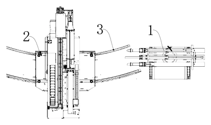
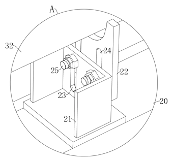
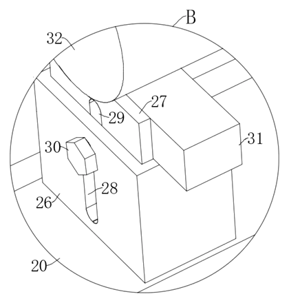
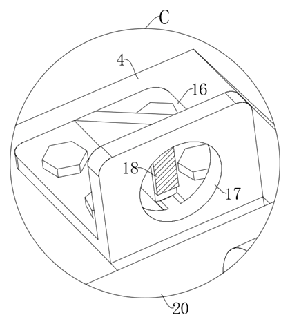
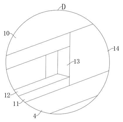
Drawings reproduced from the public patent document for reference.