At a glance
| Patent number | CN116922342B (application CN202311110900) |
| Type | China invention patent - protects product structure and method |
| Original title | Portable insulating blanket clamp placement rack (便携式绝缘毯夹放置架) |
| Patent owner | Xinjiang Huiyuan Electric Power Co ltd |
| Inventors | Kaimuerjiang Yusufu, Ababaikere Alimu, Song Zhandang, Meng Xiandong, Li Zhibo, Chen Yongfeng, Ma Liangzhicong, Chen Shilin, Zhu Qianfeng, Yang Haoyi, Wang Hui, An Zeng, Maimaitaili Ruzemaimaiti, Zhang Xiaokai, Wang Zeliang |
| Filing date | 2023-08-29 |
| Grant date | 2025-05-16 |
| Status (China) | In force - term ends at most on 2043-08-29, subject to annual fee payments |
| Patent family | Chinese filings only - no US, European, Japanese, PCT or other filings listed |
| Cited by | 0 later documents |
| Source | Google Patents (search for CN116922342B) |
What the claims cover, in plain language
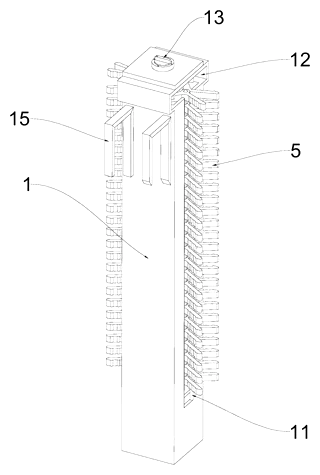
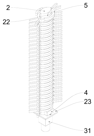
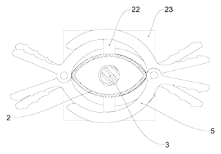
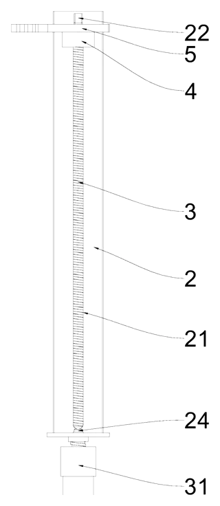
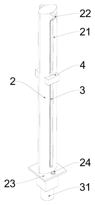
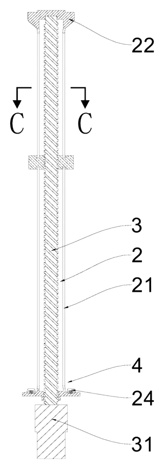
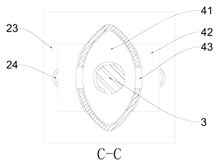
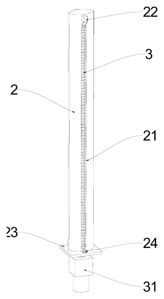
Claim 1 defines a portable rack for insulating blanket clamps. Key structural elements include a housing with opposing side slots, a central fixing column with a spindle-shaped cross-section, and a lifting mechanism. The lifting mechanism comprises a motor, a lead screw, and a lifting top block threaded onto the screw. The column’s shape matches the inner curvature of the clamp’s jaw. The bottom clamp rests on the lifting block, which moves vertically to raise or lower the stack.
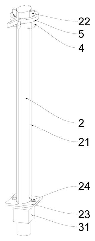
Claim 2 specifies the housing is a quadrangular prism with a picking portion on top. This picking portion has a through-hole wider than the housing, connecting to the side slots, and sits higher than the external hook.
Claims 3-6 detail the internal arrangement: the lead screw is inside the column; the lifting block consists of inner and outer sections connected by columns passing through perpendicular slots in the fixed column; wedge blocks are located at the top of these slots to interact with the rising clamps.
Claims 7-9 describe the drive system: a reversible reduction motor at the bottom drives the screw. Two normally open limit switches (one at the top, one at the bottom) cut power to the motor when the lifting block reaches the end of its travel. A control switch manages the motor direction.
Claim 10 adds an external hook on the housing side perpendicular to the slots for mounting.
This is a simplified reading for orientation only. The legal scope is defined by the exact claim wording in the official Chinese document.
What this means for US production
This patent was filed only in China and is currently in force. Making, using, selling, or importing this specific design into the United States does not infringe this Chinese patent directly, as patents are territorial. However, exporting products made under this license or copying the design without a license could violate Chinese law if manufactured there.
Two points to settle early:
- Other patents may exist. Electrical safety tools and automated storage systems are active fields. A freedom-to-operate (FTO) review is recommended to check for US patents covering similar lead-screw lifting mechanisms or spindle-shaped tool holders.
- Component sourcing. The motor, lead screw, and switches are standard industrial components. Sourcing must ensure compatibility with US voltage standards (110V/60Hz) and safety certifications.
Customization and manufacturing
What can be customized
| Area | Options |
|---|---|
| Column Material | Aluminum alloy, stainless steel, or reinforced polymer |
| Motor Type | DC brushless, stepper, or AC geared motor (voltage/frequency dependent) |
| Capacity | Number of clamps held depends on column length and clamp size |
| Finish | Powder coating, anodizing, or bare metal |
| Controls | Wireless remote, wired button, or foot pedal options |
| Mounting | Hook style, magnetic base, or strap attachment |
Things to plan for (US market)
- UL Certification: If powered by mains electricity, the motor and wiring assembly likely needs UL recognition or listing for safety.
- OSHA Standards: General workplace safety rules apply to tool storage and electrical equipment usage.
- IP Rating: Dust and water ingress protection (e.g., IP54 or higher) should be specified for outdoor utility work.
- Battery Compliance: If using rechargeable batteries, UN 38.3 transport testing is required.
How a project runs
- Inquiry - Define clamp dimensions, capacity, and power source (battery vs. corded).
- Design - Finalize column profile, lead screw pitch, and switch placement.
- Prototype - Build functional samples for lifting speed and ease-of-grab tests.
- Testing - Verify limit switch reliability and motor torque under load.
- Production - Mold housings, machine columns, assemble electronics.
Quantities & timeline
Tooling for the plastic housing and aluminum column will take several weeks. Lead times depend on motor availability. Send us your target quantity, power requirements, and desired clamp capacity and we will reply with options.
Production notes
Tooling and process
The housing likely requires injection molding for complex shapes. The spindle column is typically machined from aluminum or steel bar stock. The lead screw is usually purchased off-the-shelf or machined. Assembly involves fitting the motor, screw, and lifting block into the column.
Cost drivers
Machining the precise spindle profile typically adds cost. Motor selection impacts price significantly. Injection mold tooling for the housing is a major upfront expense. Surface finishing for corrosion resistance also contributes.
Prototyping path
Start with 3D-printed housing prototypes to test fit. Machined aluminum for the column is likely needed to verify the clamp interaction. Integrate standard motors and screws for initial function validation before final tooling.
What we would change before tooling
Consider simplifying the wedge block mechanism if manual separation proves sufficient. Evaluate if a simpler linear actuator could replace the lead screw for lower cost. Check if the limit switches can be integrated into the motor driver module.
Common failure points
Lead screw binding is likely if misaligned. Limit switch failure leading to over-travel. Housing cracking under impact. Motor burnout from jammed clamps. Corrosion of the column affecting smooth sliding.
Patent drawings
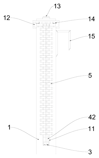
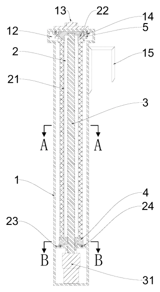
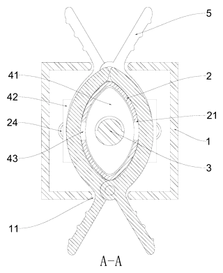
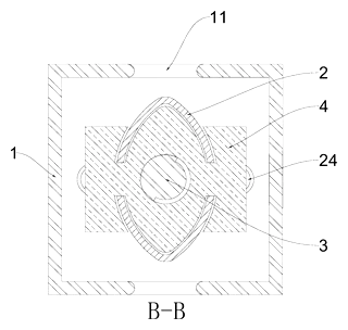
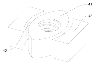
Drawings reproduced from the public patent document for reference.