
Patent CN117325770B
Updated November 3, 2026High-Strength Automobile Luggage Rack with Arc-Section Connecting Pieces
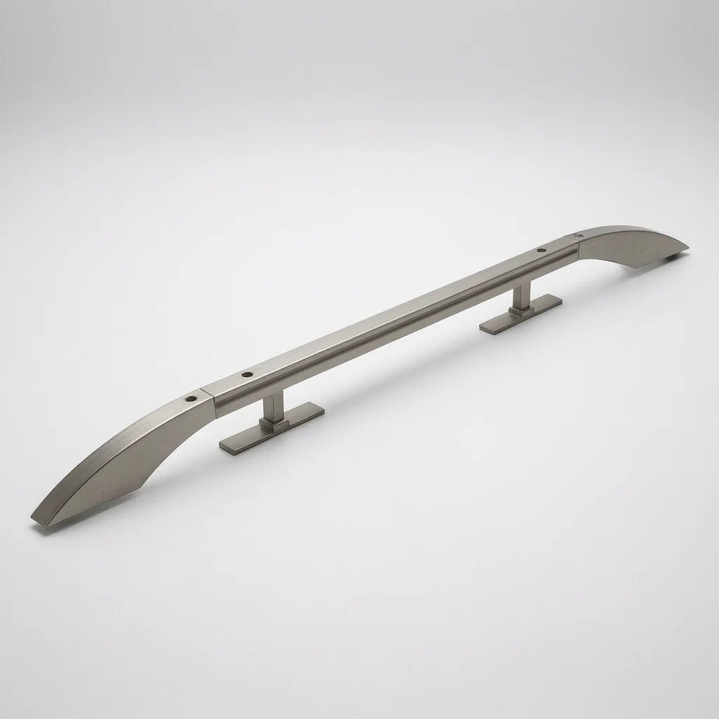
Standard car roof racks often fail at the connection points between the crossbar and the mounting foot. When heavy cargo is placed on the bar, the joint can twist or deform because the load is transferred through small contact areas. This patent describes a reinforced structure where the connecting piece has an arc-shaped section that fits snugly into the crossbar, spreading the force more evenly. Additionally, a vertical section of the connector acts as a strut, transferring weight directly down to the roof surface rather than relying solely on the bolted joint. To facilitate manufacturing, the patent includes a mechanical assembly jig that locks these components together quickly without complex tools.
- China invention patent - active
- No filings outside China
- Automotive exterior accessories
- Reinforced joints, quick-assembly jig
Splat! What let you down?
🏋️
Anti-Deformation
Vertical connector sections support the crossbar directly against the roof to prevent bending.
🔗
Arc-Shaped Links
Curved connection areas increase contact surface, reducing stress at the joint.
⚡
Quick Assembly Unit
A dedicated mechanical jig allows rapid locking of parts by rotating a single pressure rod.
🛡️
Rubber Protection
Pads inside the sliding grooves protect metal surfaces from damage during installation.
Bring this product to market
- ✓ Patent vetted China-only family and legal status checked
- 2 Product brief · now How it works, uses and options written up
- 3 Prototype First samples for buyers to review
- 4 Pilot run Small first batch for launch customers
- 5 Volume production Repeat orders at scale
Buyer interest
– of 100 buyers needed to start prototyping
One click, no sign-up. Each vote is one real visitor, and products with the most interest go to prototyping first.
Build team: no members yet. Need a partner, co-funding or skills to build this? Join and we introduce the team once it forms.
The problem
Traditional automobile luggage racks typically consist of a simple crossbar plugged into fixed seats mounted on the vehicle roof. These connections rely heavily on bolts passing through small holes. When the rack carries heavy items—such as kayaks, rooftop tents, or large cargo boxes—the weight exerts significant torque on the crossbar ends. Because the contact area between the straight crossbar and the flat mounting seat is limited, this stress concentrates at the joint. Over time, or under sudden heavy loads, the crossbar can deform or bend near the connection point, compromising the structural integrity of the rack. Furthermore, assembling these multi-part systems often requires aligning multiple bolts simultaneously, which slows down production and makes DIY installation difficult for end-users.
The solution
This patent introduces a reinforced connection structure and a specialized assembly method.
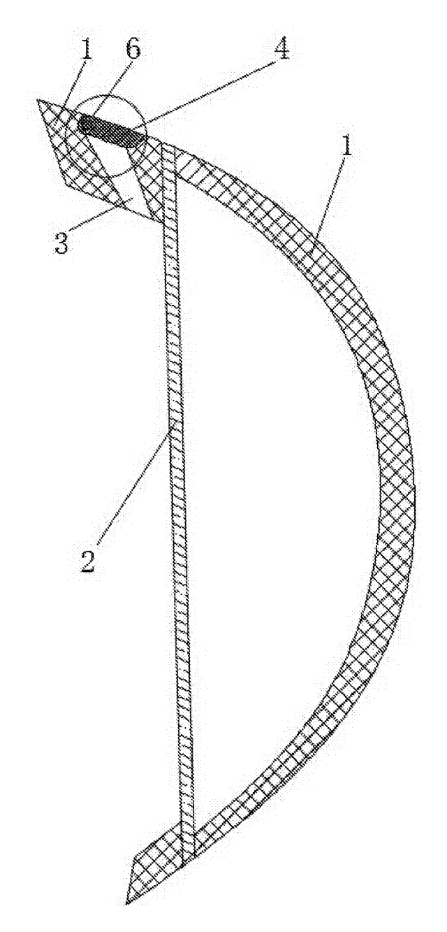
- Crossbar Design: The main crossbar features symmetric round holes for counter-bore bolts on its upper face. Crucially, the lower face contains a longitudinal “limit sliding groove.”
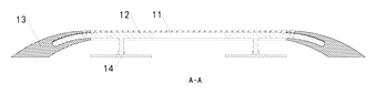
- Connecting Pieces: Instead of simple plugs, the rack uses two connecting pieces per side that slide into this groove. Each piece comprises three distinct sections:
- A horizontal section that slides within the limit groove.
- A vertical section that extends downward to act as a support strut.
- An arc-shaped section that connects the horizontal and vertical parts, fitting closely against the rounded end of the crossbar.
- Load Distribution: The arc shape increases the contact area between the connector and the crossbar, distributing stress more evenly than a flat interface. When loaded, the vertical section presses against the vehicle roof, providing direct physical support that prevents the crossbar from bending downward.
- Assembly Unit: To manufacture these racks efficiently, the patent details a mechanical assembly table. It uses a linkage system, gear sets, and a pressing assembly. Operators place the crossbar and seats in designated slots, then rotate a pressure rod downward. This action drives the components into alignment and locks them together, simplifying the assembly process significantly.
Who it is for
- Automotive Accessory Brands: Companies looking to differentiate their roof rack lines by marketing higher load capacities and resistance to deformation compared to standard aluminum extrusion racks.
- Manufacturers of Rooftop Cargo Systems: Businesses producing racks specifically for heavy outdoor gear like kayaks or camping tents, where structural failure poses safety risks.
- Aftermarket Parts Suppliers: Distributors who need durable replacement racks for SUVs and trucks, focusing on long-term reliability and ease of installation.
- OEM Contract Manufacturers: Factories seeking automated or semi-automated assembly solutions that reduce labor costs and assembly time through the patented quick-lock jig concept.
How it works
The main parts
The system relies on the interaction between the crossbar, the unique connectors, and the mounting feet.
| No. | Part | What it does |
|---|---|---|
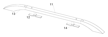
| 11 | Cross Rod | Main horizontal beam with internal sliding groove and bolt holes. |
| 12 | Connecting Piece | Slides into the rod; features horizontal, vertical, and arc sections. |
| 13 | Fixed Seat | Mounts to the vehicle roof; receives the connecting piece. |
| 14 | Rubber Pad | Sleeved in the groove to prevent metal-on-metal damage. |
| 21 | Assembly Table | Base structure for the manufacturing jig. |
| 22 | Linkage Assembly | Moves connectors into position via gears and rods. |
| 24 | Pressing Assembly | Applies downward force to lock parts during assembly. |

Operating steps
- Installation on Vehicle: The fixed seats (13) are bolted to the car roof rails. The crossbar (11) is positioned above them.
- Sliding Connection: The connecting pieces (12) are inserted into the limit sliding groove of the crossbar. The arc-shaped section wraps around the end of the bar.
- Bolting: Counter-bore bolts pass through the crossbar holes and thread into the horizontal section of the connecting piece, securing the joint.
- Load Bearing: When cargo is placed on the bar, the vertical section of the connector transfers the load directly to the roof surface, while the arc section distributes stress along the bar’s length.
- Factory Assembly: In production, the rack parts are placed on the assembly table (21). Rotating the pressure rod engages the linkage (22) and gears (25), pushing the connectors into the crossbar and seats simultaneously to snap them into final position before bolting.
Applications
Heavy-Duty Kayak Transport
Kayaks create uneven leverage on roof racks. The vertical support strut prevents the crossbar from bowing under the long, rigid hull, ensuring the kayak remains level and secure during transit.
Rooftop Tent Camping
Rooftop tents add significant static weight and dynamic wind load. The arc-shaped connectors distribute this stress over a larger area of the crossbar, reducing the risk of fatigue cracks at the mounting points.
Commercial Fleet Vehicles
Delivery vans and service trucks often carry ladders or pipes that extend beyond the rack edges. The robust connection design withstands the twisting forces generated by off-center loads better than standard plug-in racks.
Off-Road Adventure Gear
For vehicles used in rough terrain, vibrations can loosen standard joints. The tight fit provided by the sliding groove and rubber pads, combined with the structural bracing, maintains rigidity despite constant shaking.
Where it is less suitable
- Lightweight Urban Commuters: For users carrying only light backpacks or small boxes, the added complexity and weight of the reinforced connectors may be unnecessary compared to basic economy racks.
- Non-Standard Roof Rails: The fixed seats require specific bolt patterns compatible with common roof rail systems; custom-fit applications may need adapter plates not described in this patent.
Frequently asked questions
Why is this rack considered “high-strength”?
Standard racks often bend at the ends where they meet the roof mounts. This design adds a vertical support section to the connector that rests against the roof, transferring weight directly down instead of relying only on the bolt. The arc-shaped section also spreads stress over a wider area of the crossbar.
Does it require special tools to install?
For the end-user, installation is similar to standard racks: place the crossbar on the seats and tighten bolts. However, the patent describes a specialized assembly jig used in factories. This jig allows workers to lock the components into place by rotating a single pressure rod, speeding up production but not required for consumer installation.
Can I use this design for heavy cargo like kayaks?
Yes. The structural reinforcement is specifically aimed at preventing deformation under load. The vertical strut acts as a brace, making it suitable for heavier, longer items that create leverage on the crossbar ends.
What materials are used?
The patent focuses on the structural shape rather than specifying a single material. Typically, such racks are made from aluminum alloys for a balance of weight and strength, or steel for maximum durability. Rubber pads are included to protect the metal surfaces.
Is the assembly jig necessary for my business?
If you are manufacturing racks in volume, the jig described in the patent can significantly reduce assembly time and ensure consistent alignment. For small-scale or custom builds, manual assembly is possible, but the jig offers efficiency advantages.
How does the rubber pad help?
The rubber pad is sleeved inside the sliding groove of the crossbar. It prevents the metal connecting piece from scratching or damaging the crossbar during sliding and tightening, and also helps dampen vibration noise while driving.
Can this design be made and sold in the US?
The patent is currently in force in China but has no US counterpart. Therefore, it does not restrict sales in the US. However, the automotive roof rack market is highly competitive with many existing US patents. We strongly recommend a freedom-to-operate (FTO) check to ensure your specific implementation does not infringe on other active US patents.
Are you affiliated with the patent owner?
No. IP2M is an independent design and manufacturing service working from the public patent document.
Request a quote
Click Request a Quote below to see our email address - copy it, or open your email app with a ready-made message. Please mention patent CN117325770B in the subject.
Helpful details to include:
- Your company and channel (auto accessory brand, fleet supplier, aftermarket distributor)
- Target vehicles (make/model/year) and roof rail types
- Load requirements (static and dynamic weight limits)
- Material preference (aluminum, steel) and finish
- Estimated quantity and target price
- Timeline - when you would like prototypes and mass production
You can also reach us at (332) 203-9997.
Explore this product
Interested in building this?
Tell us your target market, quantity and timeline. We reply with options for prototyping, small-batch runs or volume production.
Send your inquiry to
Please put CN117325770B in the subject line and tell us your company, country, estimated quantity and timeline.
Prefer to talk? Call (332) 203-9997.
More product-ready patents
All Car Accessories patents →
Car Accessories
Car Headrest Pillow with Ratchet Side Wings and Push-Button Reach
Post-mounted car headrest pillow with ratchet side wings and a push-button forward adjustment.
Patent CN212195197U
Car Accessories
Hard-Shell Rooftop Tent That Doubles as a Cargo Box
Roof box whose hard frames lift on gas struts into a tent with door and skylight, and fold back for luggage.
Patent CN206327275U
Car Accessories
Headlamp-to-Bumper Adapter Bracket That Sets Gap and Flush in Three Directions
Molded bracket under the headlamp: support blocks and snap teeth locate the bumper flange for an even gap.
Patent CN216580316U
Car Accessories
Infant Car Seat with a Load-Bearing Base That Wraps the Carrier
Infant car seat whose base has a backrest and swing-up side rails, so the carrier can be lighter.
Patent CN206383856U
Car Accessories
Retractable Side Impact Protection Block for Child Car Seats
Retractable side-impact block for child seats: springs out to provide side-impact buffering, folds flat.
Patent CN207028930U
Car Accessories
Rain-Deflecting Side Mirror with a Pivoting Air-Guide Plate
Side mirror with a top air duct and folding guide plate that directs airflow across the glass.
Patent CN207345672U
Browse by category
- Apparel & Accessories (31)
- Baby & Kids (23)
- Bags & Luggage (13)
- Bath & Personal Care (22)
- Car Accessories (19)
- Furniture, Bedding & Storage (17)
- Garden & Outdoor (25)
- Health & Wellness (10)
- Home, Kitchen & Cleaning (36)
- Lighting (17)
- Packaging & Containers (9)
- Pet Products (8)
- Phone & Camera Accessories (6)
- Retail Display (18)
- School, Office & Art (25)
- Sports & Recreation (32)
- Tools & Workshop (41)
- Toys & Games (17)
This page is based on the public patent document CN117325770B, assigned to Qiao Luming Technology Co ltd. IP2M is an independent manufacturing service and is not affiliated with, endorsed by or licensed by the patent owner. Images marked as concept renderings are illustrations, not photos of an existing product. Patent status information is provided for reference only and is not legal advice; confirm freedom to operate for your market before production. Full disclaimer.