
Patent CN117944747B
Updated November 7, 2026Adjustable Potted Plant Handling Cart with Rotating Platforms
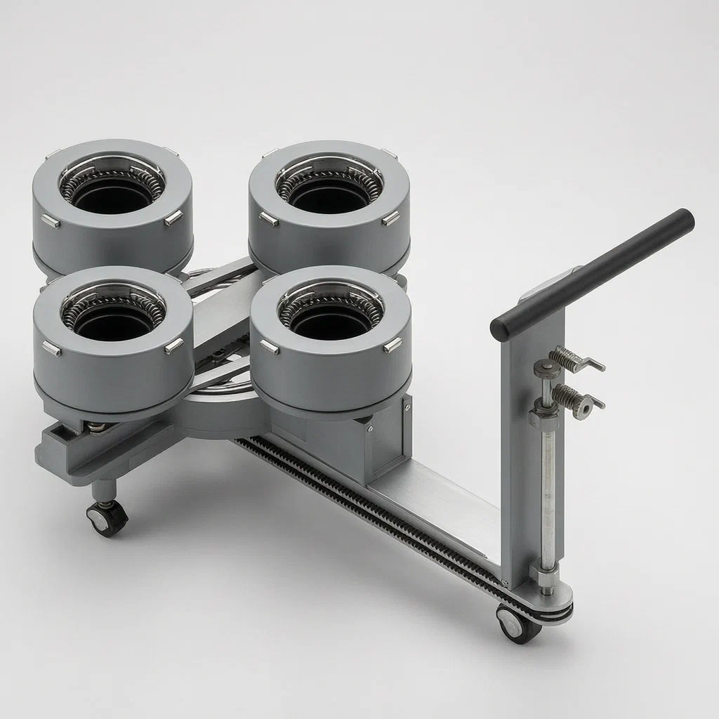
Moving potted plants in bulk often leads to damaged branches, unstable loads, and inefficient use of cart space. This handling device solves those issues with a mechanical design that adjusts both the spacing and the grip on each pot. At its center is a rotating plate driven by a belt from the push handle. As it turns, linkage rods push side frames outward, widening the gap between front and rear platforms to accommodate taller branches. Simultaneously, arc-shaped guide rails ensure the left and right platforms move in sync. Each platform holds the pot via a spring-loaded cylinder; placing a heavy pot compresses the spring, forcing radial pads inward to clamp the pot firmly without manual adjustment. This creates a stable, adjustable transport solution for garden contractors.
- China invention patent - in force
- No filings outside China
- Garden equipment & logistics
- Steel frame, injection molded parts, spring mechanisms
Splat! What let you down?
🔄
Rotating adjustment
A central rotating plate widens the gap between platforms to clear tall plant branches.
📏
Synced spacing
Arc guide rails and linkages keep all four platforms moving together in step.
🤖
Auto-clamping
Spring-loaded pads clamp the pot automatically when weight is placed on the platform.
🛞
Mobile base
Universal wheels and a swingable push handle allow easy maneuvering on uneven ground.
Bring this product to market
- ✓ Patent review Patent family and legal status reviewed in the relevant jurisdictions.
- 2 Product brief · now How it works, uses and options written up
- 3 Prototype First samples for buyers to review
- 4 Pilot run Small first batch for launch customers
- 5 Volume production Repeat orders at scale
Buyer interest
– of 100 buyers needed to start prototyping
One click, no sign-up. Each vote is one real visitor, and products with the most interest go to prototyping first.
Build team: no members yet. Need a partner, co-funding or skills to build this? Join and we introduce the team once it forms.
Patent Rights & Team Participation
Before joining a development team, participants should ensure they have the necessary rights or authorization to participate in the project.
Participation is generally appropriate where:
- You own the relevant patent rights or have obtained permission or a license from the rights holder.
- The relevant patent rights have expired or have been legally invalidated in the jurisdictions where the planned activities will take place.
- The planned development, manufacturing, and commercialization activities have been independently assessed and do not infringe applicable patent rights in the relevant jurisdictions.
Important: Being located outside a country where a patent is protected does not automatically exempt you from patent infringement risks. Patent rights may apply based on where development, manufacturing, use, sale, or import activities take place.
IP2M does not grant any patent license or authorization through team participation. Joining a project does not provide permission to use, manufacture, or commercialize patented technology.
The problem
Garden contractors transporting large volumes of potted nursery stock face three main challenges. First, fixed-distance carts waste space or cause collisions; if pots are too close, branches intertwine and break. Second, securing pots manually is slow and inconsistent; loose pots tip over on uneven terrain, while overly tight clamps crush plastic containers. Third, adjusting the cart’s configuration usually requires stopping, kneeling, and turning screws, which halts workflow. Existing hand trucks lack integrated mechanisms to simultaneously adjust horizontal spacing and vertical clearance, leading to inefficient loading and potential product damage during transit.
The solution
This device integrates a mechanical transmission system into a wheeled cart to solve these issues dynamically.
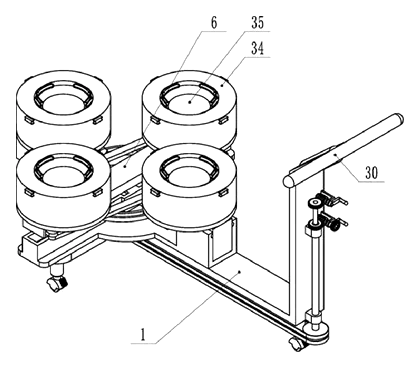
- Base Structure: A bottom plate equipped with universal wheels provides mobility. A vertical plate at the front supports a push handle that can swing left and right.
- Central Rotation: A bearing plate sits on the base, holding a central rotating plate. This plate is driven by a shaft connected to the handle via a belt-and-pulley system.
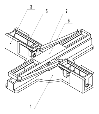
- Spacing Adjustment: When the operator turns the handle control, the rotating plate spins. Linkage rods attached to the sides push movable frame plates outward. This action expands the distance between the front and rear placement platforms, creating vertical space for tall branches.
- Synchronized Movement: Arc-shaped guide rails mounted on a box above the bearing plate interact with sliding blocks on the rotating plate. As the plate rotates, these blocks slide along the arcs, ensuring the left and right platforms move in precise synchronization with the front and rear ones.
- Pot Clamping: Each platform features a connecting cylinder with an open top. Inside, multiple displacement sliders with fixing pads are arranged radially. A guard bar with a return spring supports a mounting cylinder topped by a placement board. When a pot is placed on the board, its weight pushes the board down, compressing the spring. Through a conductive structure and lever arms, this downward motion forces the radial pads inward, clamping the pot securely without manual intervention.
Who it is for
- Landscape Contractors: Teams that need to move hundreds of potted shrubs and trees efficiently across job sites without damaging foliage.
- Nursery Logistics Staff: Workers who handle mixed sizes of potted plants and require adaptable spacing to prevent cross-contamination or branch tangling.
- Municipal Greening Crews: Public works teams transporting young trees for planting projects where speed and plant survival rates are critical.
- Equipment Manufacturers: Brands looking to add a specialized, high-efficiency handling tool to their garden machinery lineup.
How it works
The main parts
The device consists of several interconnected mechanical assemblies that translate simple handle inputs into complex spatial adjustments.
| No. | Part | What it does |
|---|---|---|
| 1 | Bottom Plate | Base chassis with universal wheels for movement. |
| 4 | Bearing Plate | Stationary support structure for the rotating assembly. |
| 6 | Rotating Plate | Central disc that drives the expansion of platform spacing. |
| 7 | Hinged Rods | Connect the rotating plate to the movable frame plates. |
| 5 | Movable Frame Plates | Slide back and forth to change the front-to-rear distance. |
| 11 | Arc Guide Rails | Ensure synchronized movement of the side platforms. |
| 34 | Connecting Cylinder | Housing for the pot-clamping mechanism. |
| 38 | Return Spring | Provides the force to retract clamping pads. |
| 39 | Displacement Sliders | Radial arms that move the fixing pads inward/outward. |
| 22 | Transmission Shaft | Links the handle controls to the internal gears. |
Operating steps
- Position the Cart: Roll the device to the loading area using the push handle. Swing the handle left or right to navigate tight spaces.
- Adjust Spacing: Turn the control handle at the front. The belt drive rotates the central plate. Hinged rods push the front and rear frames apart, while arc guides move the side platforms outwards. This opens up the “footprint” of the cart.
- Load Pots: Place potted plants onto the individual placement boards.
- Secure Automatically: As the pot rests on the board, gravity pushes the board down against the return spring. The internal lever system converts this downward force into inward radial pressure, locking the pot in place with the fixing pads.
- Transport: Move the loaded cart to the destination. The universal wheels allow omnidirectional rolling.
Applications
Nursery Stock Transport
Contractors moving delicate ornamental shrubs benefit from the adjustable spacing. By widening the gap between platforms, they prevent branches from rubbing against each other during transit, reducing leaf loss and breakage.
Tree Planting Projects
For larger saplings with expansive root balls, the auto-clamping feature ensures stability. The radial pads grip the container securely, allowing workers to push the cart over rough grass or gravel without worrying about pots tipping over.
Greenhouse Management
Inside narrow greenhouse aisles, the ability to swing the push handle and rotate the wheel base helps maneuver the cart around obstacles. The compact folded state (when spacing is minimized) allows easier storage between uses.
Municipal Park Renovation
Teams replacing flower beds often handle mixed varieties of plants. The device accommodates varying pot diameters instantly due to the self-adjusting clamps, eliminating the need for different sized trays or manual strapping.
Where it is less suitable
- Very Heavy Trees: The spring mechanism is designed for standard nursery pots; extremely heavy mature trees may overwhelm the return springs or bend the thin steel frames.
- Irregular Containers: Pots with non-circular bases or protruding handles may not sit flat on the circular placement board, potentially compromising the clamping effectiveness.
- High-Speed Transit: This is a manual push cart; it is not designed for attachment to vehicles or rapid industrial conveyor systems.
Patent & Production
At a glance
| Patent number | CN117944747B (application CN202410334061) |
| Type | China invention patent (发明专利) - protects method and structure |
| Original title | Seedling Pot Plant Carrying Device for Garden Construction (一种园林施工的苗木盆栽搬运装置) |
| Patent owner | Zhengyuan Energy Group Co ltd |
| Inventors | Hu Xiaozhou, Yang Zedong, Yang Zhengxi, Lu Cui, Wang Peimin, Liu Jibin, Yue Xiaoming, Zhao Yanpu, Liang Ming, Hu Shiwei, Ji Lili, Zhu Mingxia, Jia Zhengyi, Zhu Hongen |
| Filing date | 2024-03-22 |
| Grant date | 2024-06-11 |
| Status (China) | In force - valid until at most 2044-03-22, subject to payment of annual fees |
| Patent family | Public record shows Chinese filings only - no US, European, Japanese, PCT or other filings listed |
| Cited by | 0 later documents |
| Source | Google Patents (search for CN117944747B) |
What the claims cover, in plain language
Claim 1 describes a garden construction seedling pot plant carrying device comprising a bottom plate, a bearing plate, and a rotating plate. The key structural elements include:
- Adjustable Platforms: Placement platforms are mounted on first and second installation sliding blocks. The distance between these platforms is adjustable via the movement of the blocks.
- Linkage Mechanism: Movable frame plates slide back and forth on the bearing plate. Hinged rods connect the rotating plate to these frame plates, driving them vertically outwards when the rotating plate turns.
- Guide System: An installation box contains arc-shaped guide rails. Second installation sliding blocks have interlocking pins that mesh with these rails, ensuring synchronized rotation and translation.
- Drive Train: A transmission shaft connects the rotating plate to a belt wheel system linked to the push handle, allowing user input to drive the mechanism.
Claim 2 details the specific pot-holding platform: a connecting cylinder with radial displacement sliders and fixing pads. A guard bar with a return spring supports a mounting cylinder and placement board. A conductive structure links the board to the sliders so that downward pressure (from a pot) causes the sliders to move inward, clamping the pot.
Claim 3 adds swinging arms and push rods to the clamping mechanism, further refining the transfer of vertical force to radial clamping motion.
Claims 4-6 specify the slide grooves for the installation blocks, the bevel gear drive components that synchronize the sliding blocks, and the pulley/belt/worm gear arrangements used to transmit power from the handle to the internal gears.
This is a simplified reading for orientation only. The legal scope is defined by the exact claim wording in the official Chinese document.
What this means for US production
This patent was filed in China and is currently in force. Making or selling this specific design in China requires the owner’s permission. However, the public record shows no US counterpart or any other foreign family members. Therefore, based on the available public records, this patent does not restrict manufacturing or sales in the United States.
Two points to settle early:
- Other patents may exist. Garden carts and material handling devices are a broad field with many existing US patents covering various adjustment mechanisms, clamping methods, and wheeled bases. A freedom-to-operate (FTO) review is recommended to ensure this specific combination of rotating plates, arc guides, and spring-loaded clamps does not infringe on earlier US utility patents.
- Mechanical Complexity. The design relies on precise alignment of arc guide rails and interlocking pins. Tolerances must be tightly controlled to prevent binding during operation, especially under load.
Customization and manufacturing
What can be customized
| Area | Options |
|---|---|
| Frame Material | Powder-coated steel tube or aluminum extrusion for lighter weight |
| Wheel Type | Solid rubber, pneumatic, or caster style depending on terrain |
| Clamp Capacity | Adjust spring rate and pad size for different pot diameters |
| Handle Design | Ergonomic grips, folding mechanisms, or fixed orientation |
| Platform Count | Scale the layout to 4, 6, or more stations per cart |
| Finish | UV-resistant coatings for outdoor durability |
Things to plan for (US market)
- OSHA General Duty Clause: Equipment must be free from recognized hazards. Sharp edges on welded frames or pinch points in the sliding mechanism should be guarded.
- ANSI B56.1 / ASME Standards: While primarily for powered industrial trucks, principles of stability and load capacity apply. Ensure the cart does not tip when fully loaded and pushed.
- California Prop 65: If using certain plastics or metal finishes, check for restricted chemicals like lead or phthalates.
- ASTM F963: If marketed near children’s play areas, toy safety standards might inadvertently apply to small detachable parts, though unlikely for this industrial tool.
How a project runs
- Inquiry - Define target pot sizes, load capacity, and quantity.
- Design - Finalize CAD models for the arc rails, spring clamps, and frame geometry.
- Prototype - Build functional samples using 3D-printed parts and coated tube samples.
- Testing - Conduct durability tests on the sliding mechanisms and spring fatigue tests.
- Production - Tooling for injection molding (clamps/housings), welding (frames), and assembly.
Quantities & timeline
Injection molds are required for the plastic clamping components and guide housings. Steel frames involve cutting, bending, and welding operations. Assembly includes fitting bearings, springs, and belts. Send us your target pot sizes, load requirements, quantity, and desired finish options and we will reply with options.
Production notes
Tooling and process
The clamping mechanisms and guide rail housings likely require UV-stabilized injection molding to withstand outdoor exposure. The main frame typically uses coated steel tube for strength and corrosion resistance. Welded frame assembly joins the base and bearing structures. Screws and rivets secure the movable plates and handles. Motor assembly is not applicable as this is a purely mechanical device.
Cost drivers
UV grade materials increase resin costs. Corrosion protection for the steel tubes adds processing steps. Packaging volume affects shipping efficiency given the bulky nature of assembled carts. Fabric grade is relevant if soft covers are added for plant protection. Actual costs typically depend on final materials, order volume, and supplier quotes.
Prototyping path
Start with 3D-printed parts to verify the arc rail interaction and spring clamp geometry. Use coated tube samples for initial fit checks. Perform UV and spray tests on finished prototypes. Build a functional sample for full cycle testing before committing to tooling. The exact sequence depends on the final design and supplier feedback.
What we would change before tooling
We would likely simplify the worm gear assembly if noise becomes an issue. Ensuring the hinge boss and pivot wear points are reinforced is critical. We might adjust wall thickness and joint design on the plastic clamps to prevent cracking under heavy pots.
Common failure points
Wind load tipping is a risk if the center of gravity is too high. Water ingress in electronics is not applicable here, but water ingress in bearings could cause rust. Seam failure in welded joints and weld rust are primary concerns. Spring fatigue and rate consistency determine the lifespan of the clamping action. Shaft and bearing alignment issues can cause the rotating plate to bind.
Patent drawings
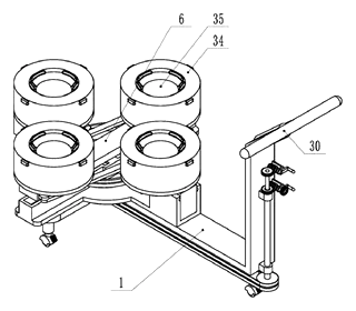
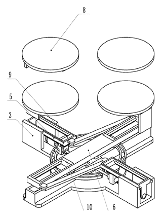
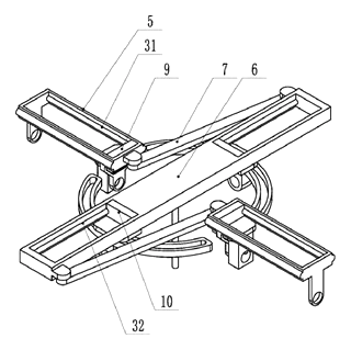
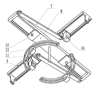
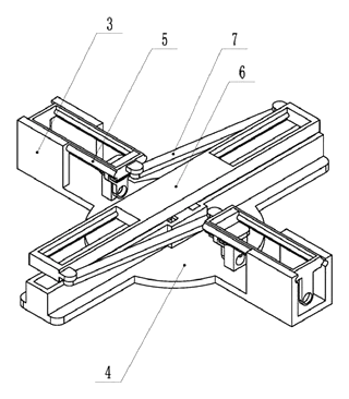
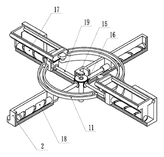
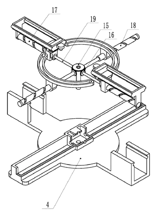
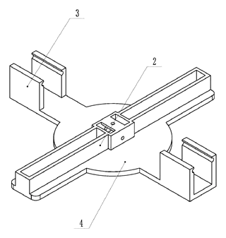
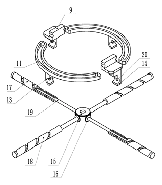
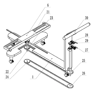
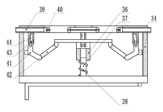
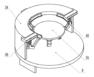
Drawings reproduced from the public patent document for reference.
Frequently asked questions
How does the pot stay in place?
The platform uses a passive spring-loaded system. When you place a pot on the board, its weight pushes the board down. This downward motion triggers a lever mechanism that moves radial pads inward, clamping the pot securely. When you lift the pot, the spring returns the pads to their open position.
Can I change the distance between plants?
Yes. Turning the handle at the front drives a central rotating plate. This plate pushes the side and end platforms outward via linkage rods and arc guides. You can expand the footprint to create more room for branches or collapse it for easier storage and transport.
Is it hard to push on uneven ground?
It uses universal wheels at the base corners, which provide better maneuverability than fixed casters. The push handle swings left and right, helping you steer around obstacles. For very rough terrain, larger pneumatic tires can be specified in the custom build.
What sizes of pots can it hold?
The patent describes a general mechanism rather than specific dimensions. The clamping pads are adjustable within the cylinder opening. In production, we can set the maximum and minimum clamp diameter by choosing the length of the slider arms and the range of the spring travel.
Does it require maintenance?
Like any mechanical cart, it needs occasional lubrication of the bearings and guide rails. The steel frame should be checked for rust if exposed to moisture for long periods. The plastic clamping parts are designed for UV resistance but should be inspected for cracks after heavy seasonal use.
Can this design be made and sold in the US?
The patent is in force in China, but the public record shows no US counterpart. Therefore, it does not restrict making or selling this design in the US. However, garden equipment is a crowded patent field, so we recommend a freedom-to-operate check to ensure no other US patents cover similar clamping or adjustment mechanisms.
Are you affiliated with the patent owner?
No. IP2M is an independent design and manufacturing service working from the public patent document.
Request a quote
Click Request a Quote below to see our email address - copy it, or open your email app with a ready-made message. Please mention patent CN117944747B in the subject.
Helpful details to include:
- Your company and channel (landscape contractor supply, nursery equipment brand, municipal procurement)
- Target pot sizes (min/max diameter) and expected load weight
- Quantity needed for pilot or full production
- Preferred materials (steel vs aluminum, plastic types)
- Timeline - when you would like samples and the first shipment
You can also reach us at (332) 203-9997.
Page editor: Emily Zhang, Product Editor · IP2M
Last updated November 7, 2026. If something on this page looks wrong, email [email protected] and we will check it against the patent.
Interested in building this?
Tell us your target market, quantity and timeline. We reply with options for prototyping, small-batch runs or volume production.
Send your inquiry to
Please put CN117944747B in the subject line and tell us your company, country, estimated quantity and timeline.
Prefer to talk? Call (332) 203-9997.
More product-ready patents
All Garden & Outdoor patents →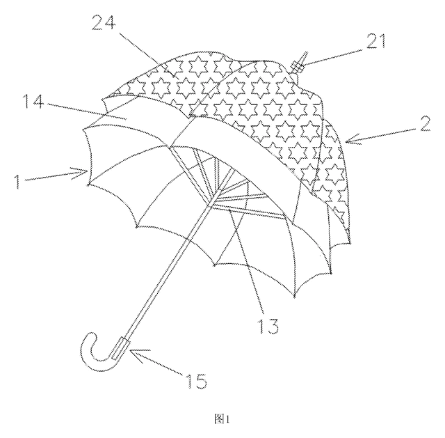
Garden & Outdoor
2-in-1 Parent & Child Umbrella
Full-size umbrella with a nested smaller umbrella on top - a rotating decorative layer that detaches into a kid-size umbrella.
Patent CN205611962U
Garden & Outdoor
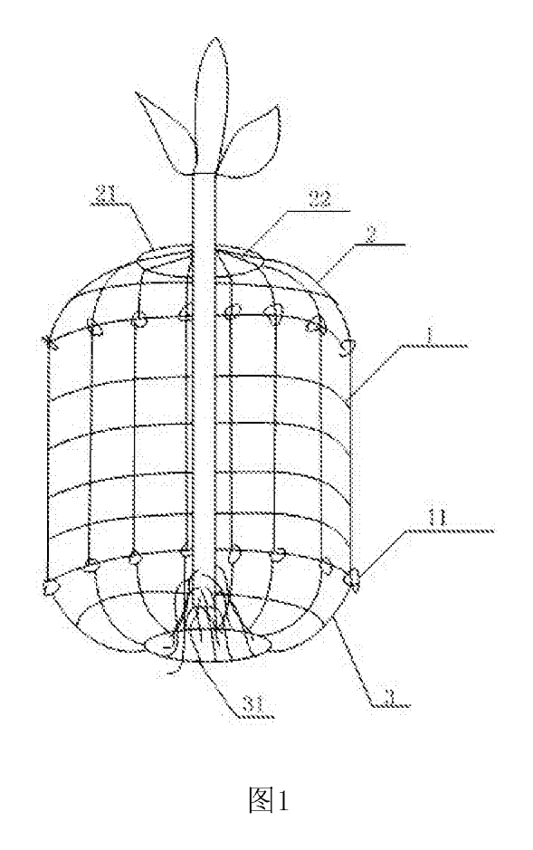
Wire-Mesh Tree Root & Trunk Guard Against Rodents
Three-part wire-mesh guard that protects the roots and lower trunk of young trees from burrowing and gnawing animals.
Patent CN206808261U
Garden & Outdoor
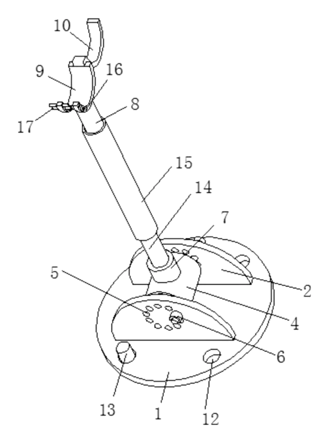
Adjustable-Angle Tree Support Prop
Tree prop with a pinned base, angle-locking hinge, twist-adjust tube and a locking trunk ring.
Patent CN208370491U
Garden & Outdoor
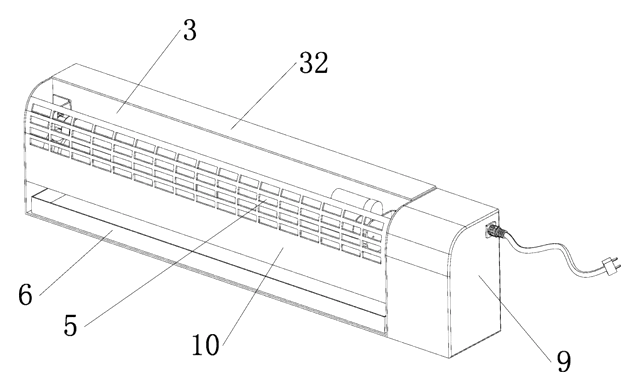
Self-Renewing Glue-Roller Mosquito Trap
UV insect trap with a glue roller that re-coats itself and scrapes the catch into a tray - no glue boards.
Patent CN217038569U
Garden & Outdoor
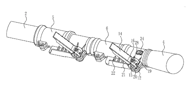
Cam-Lock Telescopic Pole for Garden Power Tools
Telescopic pole for garden power tools with cam-lever locks and a spring-button, tear-drop head socket.
Patent CN205812889U
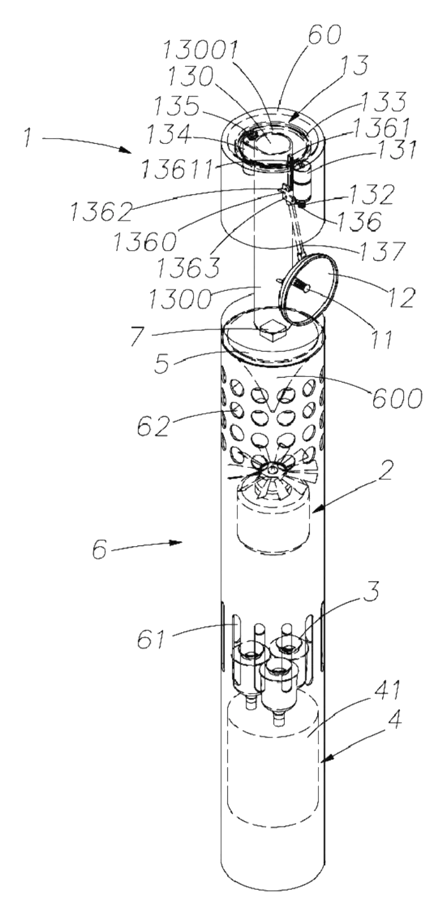
Garden & Outdoor
Mosquito Fan That Listens for Mosquitoes Before It Sprays
Fan with a scanning microphone dish that mists repellent only when it hears mosquitoes.
Patent CN208708542U
Browse by category
- Apparel & Accessories (46)
- Baby & Kids (28)
- Bags & Luggage (17)
- Bath & Personal Care (30)
- Car Accessories (25)
- Furniture, Bedding & Storage (23)
- Garden & Outdoor (32)
- Health & Wellness (14)
- Home, Kitchen & Cleaning (48)
- Lighting (23)
- Packaging & Containers (12)
- Pet Products (11)
- Phone & Camera Accessories (9)
- Retail Display (25)
- School, Office & Art (35)
- Sports & Recreation (45)
- Tools & Workshop (54)
- Toys & Games (22)
This page is based on the public patent document CN117944747B, assigned to Zhengyuan Energy Group Co ltd. IP2M is an independent manufacturing service and is not affiliated with, endorsed by or licensed by the patent owner. Images marked as concept renderings are illustrations, not photos of an existing product. Patent status information is provided for reference only and is not legal advice; confirm freedom to operate for your market before production. Full disclaimer.