At a glance
| Patent number | CN118024178B (application CN202410446918) |
| Type | China invention patent - protects product shape and structure |
| Original title | Flexible joint sleeve mounting and dismounting tool (一种柔性接头套筒安装及拆卸工具) |
| Patent owner | Yibin Sanjiang Machinery Co Ltd |
| Inventors | Feng Tao, Deng Qi, Li Guangzhi, Xu Luwei |
| Filing date | 2024-04-15 |
| Grant date | 2024-08-06 |
| Status (China) | In force until at most 2044-04-15 (if annual fees are paid) |
| Patent family | Chinese filings only - no US, European, Japanese, PCT or other filings listed |
| Cited by | 0 later documents |
| Source | Google Patents (search for CN118024178B) |
What the claims cover, in plain language
Claim 1 - a flexible joint sleeve installation and removal tool comprising a clamping ring, a pin shaft, a quick-release stop pin, and a handle. The clamping ring consists of two symmetrical semicircular ring bodies. One end of the bodies is hinged by the pin shaft; the other end is closed by inserting the quick-release stop pin. An annular clamping groove is formed on the inner circular surface of the ring to correspond to the clamp sleeve. The outer sides of the semicircular bodies have connecting ends (ear-shaped). Through holes are provided on both the semicircular ring bodies and the connecting ends to match the handle. The hinge holes are staggered. The semicircular ring bodies are integrated structures. The quick-release stop pin uses a steel ball clamping mode and is fixed to the clamping ring by an anti-drop fixing piece.
Claim 2 - the surface of the handle is provided with knurling patterns to increase friction and prevent slipping.
This is a simplified reading for orientation only. The legal scope is defined by the exact claim wording in the official Chinese document.
What this means for US production
This patent was filed only in China and is currently in force there. It has no US or other foreign counterpart. Therefore, making or selling this specific design in the United States does not infringe this patent. However, since the patent is active in China, manufacturing this exact tool in China would require permission from the owner.
Two points to settle early:
- Other patents may exist. Pipe tools and quick-release mechanisms are common fields. While this specific combination (split ring + steel ball pin + tether) appears unique to this filing, a freedom-to-operate (FTO) review is recommended to ensure no earlier US patents cover similar “clamp-on” pipe tools or specific quick-release pin geometries.
- Material Safety. The patent mentions a nylon rope for the anti-drop piece and metal for the ring/handle. Ensure materials meet US consumer safety standards for hardware tools.
Customization and manufacturing
What can be customized
| Area | Options |
|---|---|
| Ring Size | Diameters tailored to common sleeve sizes (e.g., 1/2", 3/4", 1") |
| Locking Mechanism | Steel ball detent (as patented) or alternative spring-loaded pins |
| Handle Material | Aluminum, steel, or polymer with rubber overmold for comfort |
| Finish | Zinc plating, black oxide, or powder coating for corrosion resistance |
| Tether Type | Nylon cord, Kevlar loop, or metal chain for the anti-drop feature |
| Knurling | Fine or coarse diamond/cross-hatch patterns on the handle |
Things to plan for (US market)
- ANSI B107 Series - Hand tools general requirements; while this is a specialty tool, buyers may expect durability testing consistent with ANSI standards.
- RoHS / REACH - If exporting to global markets alongside the US, material compliance for plastics (nylon tether) and metals is critical.
- Packaging - Blister packs or hang-tags typical for retail hardware stores.
How a project runs
- Inquiry - Specify target sleeve diameters and desired handle length.
- Design - CAD modeling of the split ring geometry, pin shaft location, and hole spacing.
- Prototype - CNC machined samples to test the steel-ball lock reliability and tether strength.
- Pilot Run - Small batch production to verify stamping/molding tolerances and assembly ease.
- Production - Stamping or casting for rings, injection molding for tethers/handles, assembly, and packaging.
Quantities & timeline
The clamping rings require precision stamping dies or casting molds to ensure the annular groove fits the sleeve tightly. The quick-release pins need high-tolerance machining for the steel ball interface. Handle inserts can be extruded or molded. Development time focuses on testing the “anti-drop” tether under stress. Send us your target sleeve sizes, handle preferences, quantity and target price and we will reply with options.
Patent drawings
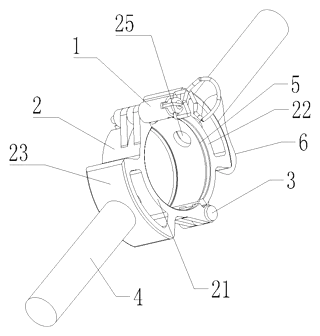
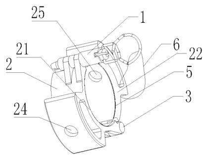
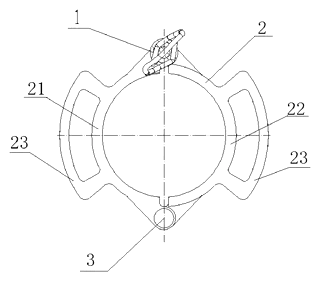
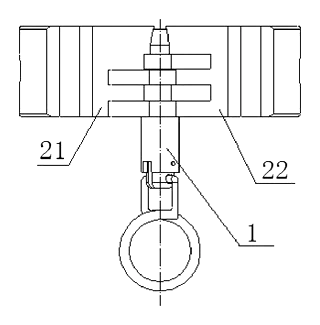
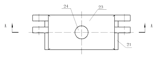
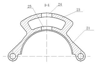
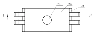
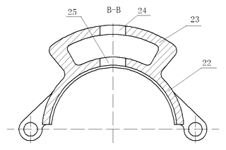
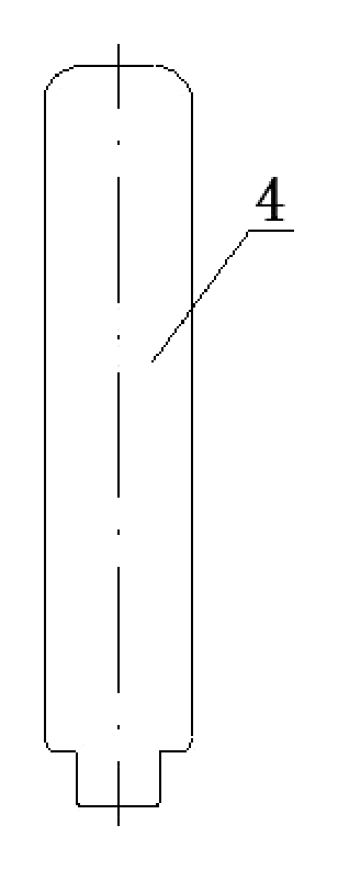
Drawings reproduced from the public patent document for reference.